Table of Contents
Advertisement
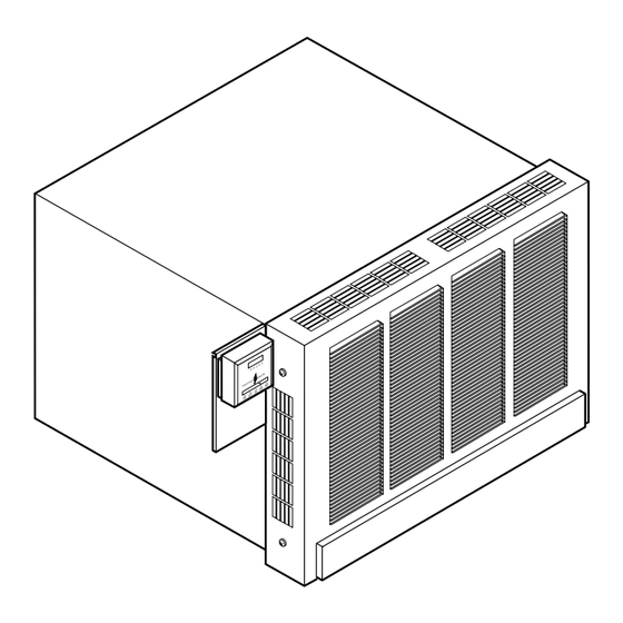
DYNAVENT
WINDOW WALL FURNACE
DIRECT-VENT NATURAL GAS HEATER
OWNER'S OPERATION AND INSTALLATION MANUAL
DNV25NB
DNV40NB
25,000 and 40,000 BTU/Hr "B" Model Furnaces
WARNING: If the information in these instructions is not
followed exactly, a fire or explosion may result causing
property damage, personal injury, or loss of life.
FOR YOUR SAFETY
Do not store or use gasoline or other flammable vapors
and liquids in the vicinity of this or any other appliance.
FOR YOUR SAFETY
WHAT TO DO IF YOU SMELL GAS
• Do not try to light any appliance.
• Do not touch any electrical switch.
• Do not use any phone in your building.
• Immediately call your gas supplier from a neighbor's
phone. Follow the gas supplier's instructions.
• If you cannot reach your gas supplier, call the fire
department.
This appliance may be installed in an aftermarket*, permanently located, manufac-
tured (mobile) home, where not prohibited by local codes.
This appliance is only for use with the type of gas indicated on the rating plate. This
appliance is not convertible for use with other gases.
* Aftermarket: Completion of sale, not for purpose of resale, from the manufacturer
Save this manual for future reference.
®
WARNING: Improper in-
stallation, adjustment,
alteration, service, or
maintenance can cause
injury or property dam-
age. Refer to this manual
for correct installation
and operational proce-
dures. For assistance or
additional information
consult a qualified in-
staller, service agency,
or the gas supplier.
— Installation and ser-
vice must be performed
by a qualified installer,
service agency, or the
gas supplier.
Advertisement
Table of Contents

Related Manuals for Dynavent DNV25NB

Summary of Contents for Dynavent DNV25NB
- Page 1 ® DYNAVENT WINDOW WALL FURNACE DIRECT-VENT NATURAL GAS HEATER OWNER’S OPERATION AND INSTALLATION MANUAL DNV25NB DNV40NB 25,000 and 40,000 BTU/Hr “B” Model Furnaces WARNING: Improper in- WARNING: If the information in these instructions is not stallation, adjustment, followed exactly, a fire or explosion may result causing alteration, service, or property damage, personal injury, or loss of life.
-
Page 2: Safety Information
® DYNAVENT DIRECT-VENT NATURAL GAS HEATER SAFETY gases will result. Carbon monoxide Surface of furnace becomes very poisoning from backed-up flue gases hot when running furnace. Keep INFORMATION could occur. The State of California children and adults away from lists carbon monoxide as a reproduc-... -
Page 3: Local Codes
**Available from: operate safely. Standards Council of Canada SPECIFICATIONS 350 Sparks Street Ottawa, Ontario K1R 7S8 DNV25NB DNV40NB This furnace must be grounded when in- *Rated Heating Input (BTU/Hr) 25,000 40,000 stalled. Follow all local codes. In the ab-... -
Page 4: Check Gas Type
® DYNAVENT DIRECT-VENT NATURAL GAS HEATER INSTALLATION LOCATING FURNACE For convenience and efficiency, install furnace: • where there is easy access for operation, This furnace is designed to be mounted in a Mounting hardware needed to mount fur- inspection, and service wall that is 4 to 18 inches thick. - Page 5 OWNER’S MANUAL INSTALLATION cabinet flange. Secure furnace to wall with toggle bolts or hook bolts set in mortar. 25,000 BTU/Hr Model: Use a proper- (Continued) sized drill bit. Drill holes through wall Insert furnace into opening. Do this and into studs at marked locations. from inside the room.
- Page 6 ® DYNAVENT DIRECT-VENT NATURAL GAS HEATER INSTALLATION Provide two 18-gauge insulated stranded wires for the thermostat wire. Also pro- (Continued) vide two wire nuts, and two wall anchors. There is a red and a white thermostat wire 6. Attach thermostat to thermostat mount- coming from the furnace.
-
Page 7: Connecting To Gas Supply
OWNER’S MANUAL INSTALLATION Wall All piping must comply with local codes Anchors and ordinances or with the National Fuel (Continued) Gas Code (ANS Z223.1 NFPA No. 54), whichever applies. 10. Feed thermostat wires from attic to You can connect furnace to gas supply at furnace through 1/2"... - Page 8 ® DYNAVENT DIRECT-VENT NATURAL GAS HEATER INSTALLATION Remove Screw, 11. Run 3/8" pipe or nipple through knock- 40,000 BTU/Hr out hole. Connect 3/8" pipe or nipple (Continued) Model Only to manifold elbow (see Figure 14). See Providing Gas Piping to Furnace,...
- Page 9 OWNER’S MANUAL INSTALLATION (Continued) Providing Gas Piping to Furnace You must provide gas piping from gas source to furnace. The gas piping must be in a vertical position where it connects to the furnace. This prevents interference with front cover installation.
-
Page 10: Checking Gas Connections
® DYNAVENT DIRECT-VENT NATURAL GAS HEATER INSTALLATION CHECKING GAS CAUTION: Use pipe joint seal- CONNECTIONS (Continued) ant that is resistant to liquid pe- troleum (LP) gas. Installation must include an equipment WARNING: Test all gas pip- shutoff valve (supplied), ground joint union,... -
Page 11: Connecting To Electrical Supply
OWNER’S MANUAL INSTALLATION CONNECTING TO ATTACHING CABINET ELECTRICAL SUPPLY FRONT COVER (Continued) IMPORTANT: Follow all local codes when Test Pressures Equal To or Less Than CAUTION: Do not operate fur- connecting electricity to furnace. In the ab- 1/2 PSIG (3.5 kPa) nace with front cover removed or sence of local codes, refer to the latest edi- 1. -
Page 12: Operating Furnace
® DYNAVENT DIRECT-VENT NATURAL GAS HEATER OPERATING B. BEFORE OPERATING smell all 5. Wait five (5) minutes to clear out any around the appliance area for gas. Be gas. Then smell for gas, including FURNACE sure to smell next to the floor because near the floor. -
Page 13: Inspecting Burner Flame
OWNER’S MANUAL OPERATING INSPECTING microswitch. When the microswitch activates, the electrical circuit is com- FURNACE BURNER FLAME pleted through the limit switch to the control module. The glo bar begins to (Continued) glow. In about 15 seconds, the glo bar To observe burner flame, remove furnace becomes hot enough to ignite the burner. -
Page 14: Cleaning And Maintenance
® DYNAVENT DIRECT-VENT NATURAL GAS HEATER CLEANING AND GASKETS CAUTION: Label all wiring MAINTENANCE Inspect all gaskets. If any gaskets show prior to disconnection when ser- signs of leakage or damage, replace them. vicing controls. Wiring errors can Safe operation of furnace depends on all... -
Page 15: Troubleshooting
OWNER’S MANUAL TROUBLESHOOTING WARNING: Turn off and unplug furnace and let cool before servic- ing. Unless you need gas supply for testing, shut off equipment shutoff Note: For additional help, visit DESA valve before servicing. Only a qualified service person should service International’s technical service web site and repair furnace. - Page 16 ® DYNAVENT DIRECT-VENT NATURAL GAS HEATER TROUBLESHOOTING Continued OBSERVED PROBLEM POSSIBLE CAUSE REMEDY No heat (continued) 7. Blower not operating 7. A. Check power supply to furnace B. Check electrical connections at furnace C. With thermostat points closed, check for cir- cuit completion at motor.
- Page 17 OWNER’S MANUAL TROUBLESHOOTING Continued OBSERVED PROBLEM POSSIBLE CAUSE REMEDY Ignition failures 1. Glo bar will not glow - with blower run- 1. Check the following: ning and microswitch engaged A. Check for 24 volts A.C. across yellow and orange wires at ignition control. If no volt- age, check microswitch and limit switch for circuit completion as well as wiring and wir- ing connections...
- Page 18 ® DYNAVENT DIRECT-VENT NATURAL GAS HEATER TROUBLESHOOTING Continued OBSERVED PROBLEM POSSIBLE CAUSE REMEDY Ignition failures 5. Burner cycles off and glo bar comes on 5. A. Check flame sensing probe. Be sure immediately, check the following: probe is positioned in the burner flame and glowing cherry red.
-
Page 19: Wiring Diagrams
OWNER’S MANUAL WIRING DIAGRAMS REPLACEMENT PARTS Limit Sail Switch Switch Thermostat Note: Use only original replacement parts. White Black This will protect your warranty coverage for Junction Green Ignition parts replaced under warranty. Time Delay Control Relay Brown Black Black Black Board PARTS UNDER WARRANTY... -
Page 20: Service Hints
® DYNAVENT DIRECT-VENT NATURAL GAS HEATER SERVICE HINTS TECHNICAL SERVICE When Gas Pressure Is Too Low You may have further questions about in- • glo-bar glows, but burner will not ignite stallation, operation, or troubleshooting. If When Gas Quality Is Bad so, contact DESA International’s Technical... -
Page 21: Illustrated Parts List
OWNER’S MANUAL ILLUSTRATED This list contains replaceable parts used in your furnace. When ordering parts, follow the instructions listed under Replacement Parts on page 19 of this manual. PARTS LIST CABINET ASSEMBLY 25,000 BTU/HR MODEL PART NUMBER DESCRIPTION QTY. 030643 Front Cover Assembly 121520 Screw, #8 x 3/8"... - Page 22 ® DYNAVENT DIRECT-VENT NATURAL GAS HEATER ILLUSTRATED This list contains replaceable parts used in your furnace. When ordering parts, follow the instructions listed under Replacement Parts on page 19 of this manual. PARTS LIST CABINET ASSEMBLY 40,000 BTU/HR MODEL PART...
- Page 23 OWNER’S MANUAL ILLUSTRATED This list contains replaceable parts used in your furnace. When ordering parts, follow the instructions listed under Replacement Parts on page 19 of this manual. PARTS LIST COMBUSTION CHAMBER ASSEMBLY 25,000 BTU/HR MODEL PART PART NUMBER DESCRIPTION QTY.
- Page 24 ® DYNAVENT DIRECT-VENT NATURAL GAS HEATER ILLUSTRATED This list contains replaceable parts used in your furnace. When ordering parts, follow the instructions listed under Replacement Parts on page 19 of this manual. PARTS LIST COMBUSTION CHAMBER ASSEMBLY 40,000 BTU/HR MODEL...
- Page 25 OWNER’S MANUAL ILLUSTRATED This list contains replaceable parts used in your furnace. When ordering parts, follow the instructions listed under Replacement Parts on page 19 of this manual. PARTS LIST BURNER ASSEMBLY 25,000 BTU/HR MODEL PART NUMBER DESCRIPTION QTY. 120717 Hex Nut, #10-24 ** 121459 Screw, #10-24 x 1/2"...
- Page 26 ® DYNAVENT DIRECT-VENT NATURAL GAS HEATER ILLUSTRATED This list contains replaceable parts used in your furnace. When ordering parts, follow the instructions listed under Replacement Parts on page 19 of this manual. PARTS LIST BURNER ASSEMBLY 40,000 BTU/HR MODEL PART...
- Page 27 OWNER’S MANUAL ILLUSTRATED This list contains replaceable parts used in your furnace. When ordering parts, follow the instructions listed under Replacement Parts on page 19 of this manual. PARTS LIST BLOWER ASSEMBLY 25,000 BTU/HR MODEL PART PART NUMBER DESCRIPTION QTY. NUMBER DESCRIPTION QTY.
- Page 28 ® DYNAVENT DIRECT-VENT NATURAL GAS HEATER ILLUSTRATED This list contains replaceable parts used in your furnace. When ordering parts, follow the instructions listed under Replacement Parts on page 19 of this manual. PARTS LIST BLOWER ASSEMBLY 40,000 BTU/HR MODEL PART...
- Page 29 OWNER’S MANUAL NOTES _______________________________________________________________________________________________ _______________________________________________________________________________________________ _______________________________________________________________________________________________ _______________________________________________________________________________________________ _______________________________________________________________________________________________ _______________________________________________________________________________________________ _______________________________________________________________________________________________ _______________________________________________________________________________________________ _______________________________________________________________________________________________ _______________________________________________________________________________________________ _______________________________________________________________________________________________ _______________________________________________________________________________________________ _______________________________________________________________________________________________ _______________________________________________________________________________________________ _______________________________________________________________________________________________ _______________________________________________________________________________________________ _______________________________________________________________________________________________ _______________________________________________________________________________________________ _______________________________________________________________________________________________ _______________________________________________________________________________________________ _______________________________________________________________________________________________ _______________________________________________________________________________________________ _______________________________________________________________________________________________ _______________________________________________________________________________________________ _______________________________________________________________________________________________ _______________________________________________________________________________________________ _______________________________________________________________________________________________ _______________________________________________________________________________________________ _______________________________________________________________________________________________ _______________________________________________________________________________________________ _______________________________________________________________________________________________ _______________________________________________________________________________________________ _______________________________________________________________________________________________ _______________________________________________________________________________________________ 201835...
-
Page 30: Warranty Information
We make no other warranty, expressed or implied. LIMITED WARRANTY DYNAVENT GAS WALL FURNACE DESA International warrants this product to be free from defects in materials and components for one (1) year and five (5) years on the combustion chamber/heat exchanger assembly from the date of first purchase, provided that the product has been properly installed, operated and maintained in accordance with all applicable instructions.
Need help?
Do you have a question about the DNV25NB and is the answer not in the manual?
Questions and answers