Hitachi NV 45AB2 Technical Data And Service Manual
Coil nailer
Hide thumbs
Also See for NV 45AB2:
- Instruction and safety manual (76 pages) ,
- Handling instructions manual (56 pages) ,
- Instruction and safety manual (56 pages)

Related Manuals for Hitachi NV 45AB2


Summary of Contents for Hitachi NV 45AB2
- Page 1 MODEL NV 45AB2 POWER TOOLS TECHNICAL DATA COIL NAILER NV 45AB2 SERVICE MANUAL LIST No. E004 Mar. 2002 SPECIFICATIONS AND PARTS ARE SUBJECT TO CHANGE FOR IMPROVEMENT...
- Page 2 REMARK: Throughout this TECHNICAL DATA AND SERVICE MANUAL, a symbol(s) is(are) used in the place of company name(s) and model name(s) of our competitor(s). The symbol(s) utilized here is(are) as follows: Competitors Symbols Utilized Company Name Model Name RN45B BOSTITCH SENCO SCN40R RN175...
-
Page 3: Table Of Contents
10-4. Disassembly and Reassembly of the Driving Section ............... 33 10-5. Disassembly and Reassembly of the Cap and the Magazine ........... 37 11. INSPECTION AND CONFIRMATION AFTER REASSEMBLY ..........39 12. STANDARD REPAIR TIME (UNIT) SCHEDULES ..............40 Assembly Diagram for NV 45AB2... -
Page 4: Product Name
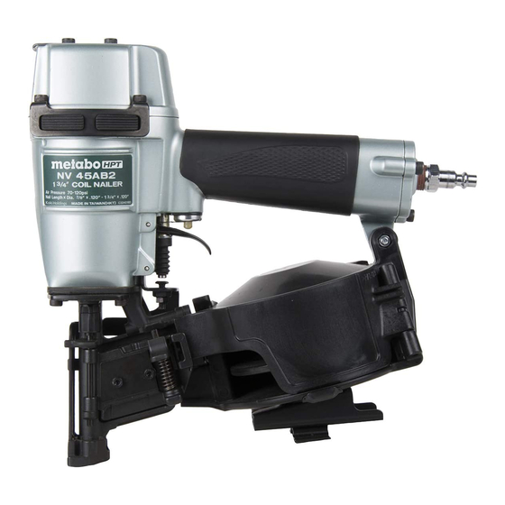
Model NV 45AB2 is equipped with a tool-less nailing depth adjuster, top loading magazine, non-slip rubber, etc. Applicable nails are the same as those of the Model NV 45AB. The Model NV 45AB2 weighs only 2.5 kg (same as the Model NV 45AB). - Page 5 The basic construction is the same as that of the Model NV 45AB except the 2-valve cylinder drive system that is well reputed for quick driving is adopted. (2) Adjuster While the Model NV 45AB requires a wrench to adjust the nailing depth, the Model NV 45AB2 requires no tool for adjustment. Too shallow...
-
Page 6: Specifications
5. SPECIFICATIONS 5-1. Specifications NV 45AB2 Model Driving system Reciprocating piston type 5 -- - 8.5 kgf/cm (70 -- - 120 psi, 4.9 -- - 8.3 bar) (Gauge pressure) Operating pressure Driving speed Min. 3 pcs./sec. Weight 2.5 kg (5.5 lbs.) -
Page 7: Nail Selection
5-2. Nail Selection The Model NV 45AB2 utilizes roofing nails which are common round-head nails collated by wire into coils from 120 nails. Applicable nail dimensions are shown below. However, it is recommended to use genuine HITACHI nails to ensure satisfactory driving quality. -
Page 8: Nail Driving Force
Sequential trip mechanism kit (Single shot) (Code No. 878226) A sequential trip mechanism kit is provided as an optional accessory for the Model NV 45AB2. By using this optional accessory, a nail is driven by pressing the pushing lever first against a workpiece and then pulling the trigger (single-shot operation), and no nail is driven when pulling the trigger first and then pressing the pushing lever against a workpiece. -
Page 9: Comparisons With Similar Products
--- 6 ---... -
Page 10: Precautions In Sales Promotion
7. PRECAUTIONS IN SALES PROMOTION In the interest of promoting the safest and most efficient use of the Model NV 45AB2 Nailer by all of our customers, it is very important that at the time of sale the salesperson carefully ensures that the buyer seriously recognizes the importance of the contents of the Instruction Manual, and fully understands the meaning of the precautions listed on the Warning Label attached to each tool. -
Page 11: Related Laws And Regulations
8. MECHANISM AND OPERATION PRINCIPLE 8-1. Mechanism As illustrated in Fig. 3, the Model NV 45AB2 can be generally divided into four sections: output section, control valve section, driving section and magazine section. Although the output section and the valve section are basically common to those of the Model NV 45AB, most of the parts of the driving section and the magazine section have been newly designed. - Page 12 The [Bold] numbers in the figure below correspond to the numbers in "8-2. Operation Principle". Accumulator [1] Exhaust Valve [4] Control valve Safety valve portion Exhaust Vent [5] section Head cap Trigger valve portion Body Exhaust cover Piston [3] Air inlet Cylinder Spring [8] Cylinder ring Driver Blade [9]...
-
Page 13: Operation Principle
8-2. Operation Principle The operation of the Model NV 45AB2 is illustrated and described in Figures 4 through 7. The [Bold] numbers in the descriptions correspond to the item numbers shown in the mechanism illustration in Fig. 3. In Figures 5 and 7, read the descriptions in alphabetical order. - Page 14 (2) When the trigger and pushing lever are operated Compressed air is applied Although air pressure is applied to both the to the upper side of the upper and lower surfaces of the cylinder, the Exhaust Valve [4], forcing it cylinder is forced downward due to the larger downward and closing Cylinder ring...
- Page 15 (3) If the trigger and pushing lever are kept pressed Air pressure is applied in the shaded areas in the illustration, and each component is held in the position illustrated. If the operator's grip is loosened, air will leak. As there is no O-ring installed here, a very small amount of air will leak from the slight clearance between the components.
- Page 16 (4) When the trigger and/or pushing lever are released The air pressure on the upper surface of the Exhaust Valve [4] is released, and the exhaust valve is pushed upward by the air pressure within the cylinder. This opens the Exhaust Vent [5], and the air pressure in the cylinder and the left-side surface of the feed piston are discharged from the nailer.
-
Page 17: Interchangeability
No difference There is a difference. Spare parts will be unified to the ones for the Model NV 45AB2. Gasket (A) [29] Thickness: 0.5 mm Thickness: 0.4 mm Nose [32] A protrusion is provided at the mounting portion of the adjuster. - Page 18 Part NV 45AB2 NV 45AB A groove for mounting the shaft ring is Nail Guide Shaft provided. [74] Groove Nail Guide [78] A protrusion for holding the magazine cover is provided. Protrusion Magazine Ass'y Bottom loading type Top loading type...
-
Page 19: Troubleshooting Guide
9. TROUBLESHOOTING GUIDE 9-1. Troubleshooting and Correction Possible cause Problem Inspection method Remedy : most-common cause) Use specified nails. Check that the magazine is <Nails> 1) Nails cannot correctly loaded with Remove the abnormal nails be driven. Magazine is not loaded with specified nails. - Page 20 Possible cause Problem Inspection method Remedy : most-common cause) Tighten screws and replace Air leaks from Gasket (A) or 1) Nails cannot gaskets. Gasket (E). be driven. Replace the O-rings. O-rings are worn or deformed. Apply grease or lubricate. O-rings need lubrication. <...
- Page 21 Possible cause Problem Inspection method Remedy : most-common cause) < Output section: Piston, Adjust the air pressure to Open the nail guide and 1) Nails cannot 4.9 --- 8.3 bar (5 --- 8.5 driver blade, etc. > perform idle driving to check be driven.
- Page 22 Possible cause Problem Inspection method Remedy : most-common cause) Set the adjuster to the 3) Nails cannot Adjuster is incorrectly set. Turn the adjuster to the optimum position. deepest driving position and be driven into then drive nails. the workpiece completely: Adjust air pressure to Air pressure is too low.
- Page 23 Possible cause Problem Inspection method Remedy : most-common cause) Check if the specified nails Use specified nails. 4) Nails jam. < Nails> are used. Remove the abnormal nails Unspecified nails are used. Check the nails as follows. and load the nailer with Abnormal nails are mixed.
-
Page 24: Possible Causes And Corrections Of Air Leakage
9-2. Possible Causes and Corrections of Air Leakage Air leakage repair location Fig. 8 --- 21 ---... - Page 25 Inspection priorities: In the table below, possible causes of air leakage and their repair procedures are marked in accordance with the likelihood of possible failure. (1) First priority items are marked with an asterisk ( ). (2) Second priority items (seal portions) are marked with a double circle ( (3) Remaining items are marked with a single circle ( ).
- Page 26 Cause Air leak part When trigger valve ON/ When trigger valve/ When trigger valve/safety valve are OFF safety valve are ON safety valve OFF Loose Hex. Socket Hd. Bolt M5 x 16 [44] Broken Gasket (D) [42] Defective seal surface of the Body Ass'y [24] or Cap [43] Defective front side O-Ring [61] of Feed...
-
Page 27: Disassembly And Reassembly
Model NV 50AA and NV 50A1, be very careful to ensure that parts from other models are not inadvertently assembled on the Model NV 45AB2. Inadvertent assembly of such parts could result in malfunction, misfiring, etc., and is very hazardous. -
Page 28: Disassembly And Reassembly Of The Output Section
10-2. Disassembly and Reassembly of the Output Section (1) Piston Bumper [27], Bumper Sheet [28] and related parts Tool required: Hex. bar wrench (4 mm) Phillips screwdriver Roll pin puller ( 3 mm (0.118")) (a) Disassembly (See Figs. 9 and 10.) Remove the Machine Screw M5 x 22 [39], and the Magazine Ass'y [109] can be disassembled. - Page 29 Remove the Hex. Socket Hd. Bolt M5 x 8 [30] and remove the Guard [31] from the Nose [32]. From Body Ass'y [24], extract the Roll Pin D3 x 30 [47] which fastens and guides the Pushing Lever [38]. Then remove the Nylock Hex. Socket Hd. Bolt M5 x 16 [34] which fasten the Nose [32], and remove the Nose [32] together with Pushing Lever [38] from Body Ass'y [24].
- Page 30 Piston Bumper [27] Damper sheet [28] Semi-circular groove Driver blade Groove Side portion of driver blade Semi-circular groove Piston (H) [13] (Driver blade) Bumper Sheet [28] Open Groove Fig. 11 (2) Cylinder [17], Piston (H) [13] and related parts: Tools required: Hex.
- Page 31 Hex. Socket Hd. Bolt M5 x 25 [1] Top Cover [2] O-Ring (S-65) [14] Exhaust Cover (B) [4] Cylinder O-Ring (A) [20] Hex. Socket Hd. Bolt M5 x 20 [5] Cylinder Guide [21] Cylinder O-Ring (B) [22] Protector [6] O-Ring (S-65) [14] Body Guard [7] Gasket (F) [8] Gasket (G) [9]...
- Page 32 (b) Reassembly Reassembly can be accomplished by following the disassembly procedures in reverse. However, special attention should be given to the following items. Assemble Piston (H) [13] so that its semi-circular grooved side is facing toward the Magzine side. (Same as paragraph 10-2-(1)-(b)) Ensure that the air vent holes on Gasket (F) [8] are properly aligned with the matching holes in Body Ass'y [24].
-
Page 33: Disassembly And Reassembly Of The Valve Section
10-3. Disassembly and Reassembly of the Valve Section: (See Figs. 15 and 16.) (1) Trigger Valve Bushing [56], Valve Bushing [51] and related parts: Tools required: Roll pin puller (3 mm (0.118")) Flat-blade screwdriver Phillips screwdriver Hex. bar wrench (4 mm) (a) Disassembly: Disassemble the magazine section and nose portion from the main body. - Page 34 Body Ass'y [24] Valve Packing [53] Urethane Ball (C) D7.14 [54] Plunger Spring [48] O-Ring (S-12) [52] Plunger O-Ring [49] Valve Plate [55] Plunger (A) [50] Trigger Valve Bushing [56] Valve Bushing [51] Trigger Plunger [57] O-Ring (S-12) [52] Plunger O-Ring [49] Trigger [58] Roll Pin D3 x 30 [47] Plunger (B) [59]...
- Page 35 (2) Adjustment of Safety Bolt [36] (See Fig. 17.) Tool required: 8 mm (0.315") spanner (a) To adjust the Safety Bolt [36], loosen the Nut M5 [37] and turn the Safety Bolt [36]. (b) Perform adjustment so that the distance between the bottom end of the Nose [32] and the bottom end of the Pushing Lever [38] is 5 0.5 mm (0.197 0.020") when the Pushing Lever [38] is pushed up so that Safety...
-
Page 36: Disassembly And Reassembly Of The Driving Section
10-4. Disassembly and Reassembly of the Driving Section (1) Nail guide portion and adjuster portion Tools required Hex. bar wrench (3 mm, 4 mm) Phillips screwdriver Roll pin puller (3 mm (0.118")) Pliers (a) Disassembly (See Figs. 18 and 19.) By following the procedures in paragraph 10-2-1-(a), disassemble the Pushing Lever [38] from the main body. - Page 37 After removing the Hex. Socket Hd. Bolt M4 x 6 [84], the Nail guide Cover [89], Main Stopper Spring [83] and Sub Stopper Spring [88] can be taken out. After removing the Roll Pin D3 x 28 [85], the Main Nail Stopper [86] and Nail Stopper [87] can be taken out. To disassemble the guide lock portion, extract the Roll Pin D3 x 10 [81] and take off the Lock Shaft [79].
- Page 38 Mount the Nail Guide Shaft [74] according to the following procedure (see Fig. 21). (I) Insert the Shaft Ring [73] between the protrusion of the Nose [32] and the Bolt [77]. Turn the Adjuster [75] counterclockwise to narrow the distance between the protrusion of the Nose [32] and the Bolt [77] for easier operation (Shaft Ring [73] becomes stable).
- Page 39 (b) Reassembly Reassembly can be accomplished by following the disassembly procedures in reverse. However, special attention should be given to the following items. Prior to reassembly, thoroughly remove any tar or dirt which may be stuck on the Guard [31] or on the sliding portion of the Feeder (A) [70].
-
Page 40: Disassembly And Reassembly Of The Cap And The Magazine
10-5. Disassembly and Reassembly of the Cap and the Magazine (1) Cap portion Tool required: Hex. bar wrench (4 mm) (a) Disassembly (See Fig. 24.) Remove the Hex. Socket Hd. Bolt M5 x 16 [44]. Then Gasket (D) [42] and the Cap [43] can be removed. (b) Reassembly Reassembly can be accomplished by following the disassembly procedures in reverse. - Page 41 Cap [43] Hex. Socket Hd. Bolt M5 x 16 [44] Gasket (D) [42] Washer [40] Machine Screw Magazine Cover [90] M5 x 22 [39] Holder Cap [91] Machine Screw M4 x 50 [92] Spring Washer M4 [93] Washer M4 [94] Holder Shaft [95] Ratchet Spring [98] Nail Holder [99]...
-
Page 42: Inspection And Confirmation After Reassembly
(3) Single guide portion Tools required: Hex. bar wrench (4 mm) Spanner (8 mm) or slender hd. pliers (a) Disassembly (See Fig. 22.) Remove the Nail Holder [99] from the Magazine Ass'y [109]. Remove the Hex. Socket Hd. Bolt M5 x 10 [108]. Then the Shingle Guide [107] can be removed from the Guide Base [105]. -
Page 43: Standard Repair Time (Unit) Schedules
12. STANDARD REPAIR TIME (UNIT) SCHEDULES Variable 60 min. MODEL Fixed Work Flow NV 45AB2 Cylinder Plate Cylinder Guide Exhaust Cover Cylinder Exhaust Valve Cylinder Ring Head Cap O-ring x 7 Piston Bumper General Assembly Trigger Plunger Pushing Lever Body... - Page 44 LIST NO. E004 PNEUMATIC TOOL PARTS LIST COIL NAILER 2002 • • Model NV 45AB2 (E1) 72 90 103 106...
- Page 45 PARTS NV 45AB2 ITEM CODE NO. DESCRIPTION REMARKS USED 949-662 HEX. SOCKET HD. BOLT M5X25 (10 PCS.) 876-179 TOP COVER 883-513 WARNING LABEL (A) FOR EUROPE 880-275 EXHAUST COVER (B) 949-757 HEX. SOCKET HD. BOLT M5X20 (10 PCS.) 883-891 PROTECTOR...
- Page 46 PARTS NV 45AB2 ITEM CODE NO. DESCRIPTION REMARKS USED 875-638 O-RING (S-12) 878-734 VALVE PACKING 875-645 URETHANE BALL (C) D7.14 875-644 VALVE PLATE 877-335 TRIGGER VALVE BUSHING 878-121 TRIGGER PLUNGER 876-203 TRIGGER 878-171 PLUNGER (B) 878-170 VALVE RUBBER COVER 872-645...
-
Page 47: Standard Accessories
NV 45AB2 PARTS ITEM CODE NO. DESCRIPTION REMARKS USED 883-898 MAGAZINE GUARD 878-213 PLATE NUT 1 FOR USA 878-176 GUIDE BASE 1 FOR USA 949-665 HEX. SOCKET HD. BOLT M5X14 (10 PCS.) 878-175 SHINGLE GUIDE 1 FOR USA 949-819 HEX. SOCKET HD. BOLT M5X10 (10 PCS.)
Need help?
Do you have a question about the NV 45AB2 and is the answer not in the manual?
Questions and answers