Table of Contents
Advertisement
Quick Links
3940011 12.12
Multiple Fireplace
Exhaust System
SYSTEM & COMPONENT DESCRIPTION
DIMENSIONS & CAPACITIES
SYSTEM INSTALLATION & SET UP GUIDELINES
ELECTRICAL CONNECTIONS & INSTALLATIONS
START-UP AND CONFIGURATION
SEQUENCE OF OPERATION
TROUBLESHOOTING
CM
C
US
READ AND SAVE THESE INSTRUCTIONS!
ENERVEX Inc.
1685 Bluegrass Lakes Pkwy.
Alpharetta, GA 30004
System Installation & Operating Manual
............................................................ Chapter 2
................................................... Chapter 5
............................................................. Chapter 6
........................................................................ Chapter 7
P: 770.587.3238
F: 770.587.4731
T: 800.255.2923
info@enervex.com
www.enervex.com
USA
CAN
......................................... Chapter 1
............................. Chapter 3
............................. Chapter 4
Job Name:
Installer:
Installation Date:
Advertisement
Table of Contents

Summary of Contents for ENERVEX Multiple Fireplace
- Page 1 System Installation & Operating Manual 3940011 12.12 Multiple Fireplace Exhaust System SYSTEM & COMPONENT DESCRIPTION ......... Chapter 1 DIMENSIONS & CAPACITIES ............Chapter 2 SYSTEM INSTALLATION & SET UP GUIDELINES ......Chapter 3 ELECTRICAL CONNECTIONS & INSTALLATIONS ......Chapter 4 START-UP AND CONFIGURATION ...........
-
Page 2: Table Of Contents
3940011 12.12 1. SYSTEM & COMPONENT DESCRIPTION 1.1 General ....................3 1.2 Component Description ...............3 1.3 System Description ................4 2. DIMENSIONS & CAPACITIES 2.1 EBC 30 ....................5 2.2 RSV .....................6 2.3 XTP2 Sensor ..................7 2.4 Stack Probe ..................7 2.5 ADF/ADM .....................8 2.6 ISOKERN IBV Fireplace ..............9 3. -
Page 3: General
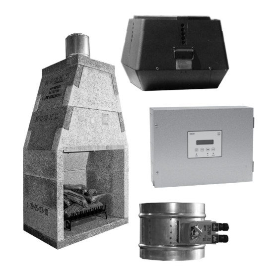
3940011 12.12 1. SYSTEM & COMPONENT DESCRIPTION 1.1 General The ENERVEX Multiple Fireplace Exhaust System is a modulating exhaust system designed specifically for the common venting and exhaust of multiple ISOKERN gas-fired fireplaces in residential, multi-story buildings. The system includes an EBC 30 Control, one or more RSV fans, an ABB Variable Frequency Drive (if applicable), an ADM automated damper, an ISOKERN IBV model fireplace and an ISOFLAMES gas log set. Each fireplace flue connects to a common vertical vent that has a RSV fan at the termination point. The EBC30 modulates the fan speed to maintain the pre-set, negative pressure in the vent. -
Page 4: System Description
ON/OFF Contact Valve ON/OFF damper and actuator with end-switch ISOKERN fireplace ON/OFF Valve Contact ON/OFF damper and actuator with end-switch ISOKERN fireplace Valve ON/OFF Contact ON/OFF damper and actuator with end-switch Stack Probe Transducer ISOKERN fireplace EBC30 Control Valve ENERVEX... - Page 5 3940011 12.12 2. DIMENSIONS & CAPACITIES 2.1 EBC 30 Control EBC 30 Control Power Supply 1x120VAC Amperage Operating Temperature °F / °C -4 to 122/-20 to 50 Range of Operation inWC / Pa 0-0.6 / 0-150 Tolerance inWC / Pa 0.01/3 +/-10% Control Signal max.
- Page 6 3940011 12.12 2.2 RSV Chimney Fan Model RSV 200 RSV 250 RSV 315 RSV 400 RSV 450 Discharge Vertical Fan Type Centrigual Impeller Max. Discharge 1,729 2,222 2,771 2,752 4,134 Velocity Actual Discharge 2.9 x 1.9 x 1.2 x 1.03 x 1.03 x Velocity Voltage...
-
Page 7: Xtp2 Sensor
3940011 12.12 2.3 XTP Sensor XTP2 Sensor Power Supply 12-36 Amperage <20 Output 0-10 Operating Temperature °F/°C 0 to 160 / -18 to 71 Accuracy inWC/Pa +/- 0.08% Dimensions D in/mm 3.70 / 94 E in/mm 5.12 / 130 F in/mm 6.18 / 157 G in/mm 3.13 / 80... - Page 8 3940011 12.12 2.5 ADM Model ADM 6 ADM 8 ADM 10 ADM 12 ADM 14 ADM 16 ADM 18 ADM 20 Dimensions Ø A Ø B 5.88 7.88 9.88 11.788 13.88 15.88 17.88 19.88 ADM 22 ADM 24 ADM 26 ADM 28 ADM 30 ADM 32 ADM 34 ADM 36 Model Dimensions Ø...
-
Page 9: Isokern Ibv Fireplace
3940011 12.12 2.6 ISOKERN IBV Fireplace Model IBV 36 IBV46 Natural Gas 70,000 77,000 Liquid Propane 65,000 69,000 Max. Inlet Supply Pressure NG in WC / Pa 7 / 1750 Max. Inlet Supply Pressure LP in WC / Pa 13 / 3250 Dimensions in / mm 43.0 / 1092 53.0 / 1346 in / mm... -
Page 10: General
DO NOT mount the transducer inside an airtight enclosure. It uses the room pressure as reference pressure. This installation manual is for the ENERVEX venting system and assumes that the ISOKERN fireplaces have already been installed. Installion of the ISOKERN fireplaces, the gas logs and the pilot assembly should be performed by a qualified ISOKERN technician or a certified gas service agent or supplier. -
Page 11: Exhaust Fan Installation
3940011 12.12 3.2 Exhaust Fan Installation Note: For more detailed installation instructions, please see the RSV Chimney Fan installation and operation manual provided with the fan. If installing a RSV 400/450, remember to REMOVE the transport securing device before installing. Fig. -
Page 12: Control, Xtp2 And Stack Probe Installation
3940011 12.12 3.3 Control, XTP2 and Stack Probe Installation EBC 30 To install the EBC 30: Fig. 5 1. Find an appropriate location, preferably, a mechanical room. 2. Mount the EBC 30 to the wall using the mounting holes located inside the control box. See Fig. 5. b. -
Page 13: Adm Installation
3940011 12.12 Stack Probe To install the stack probe: Fig. 8 1. Use w 1/4” drill bit to drill a hole in the side of the vertical common vent. Stack Probe 2. Insert the stack probe into the vertical common XTP2 Sensor Exhaust vent at the point where the draft should be kept... -
Page 14: General
3940011 12.12 4. ELECTRICAL CONNECTIONS AND INSTALLATIONS 4.1 General Danger: Turn off electrical power before servicing. Contact with live electric components can cause shock or death. EBC 30 is designed for 1x120VAC power supply only. Fan output is regulating on the neutral side and cannot be connected to other circuits. -
Page 15: Wiring The Safety Circuit
3940011 12.12 4.2 Wiring the Safety Circuit Interlock the ADM with the safety circuit of the fireplace. The actuator on the is equipped with a NO end switch circuit. The circuit closes when the damper is open and allows operation of the fireplace. If the damper closes, the circuit opens and shuts off the gas flow to the fireplace. a. Connecting to a Manual or Remote Ignition When using the manual or remote ignition options, connect a SPDT relay between the actuator and fireplace circuit. Wiring for two actuator models is shown in Fig. 11. Fig. 11... -
Page 16: Xtp2 Connections
3940011 12.12 b. Connecting to the Electronic Ignition Connect the actuator to the 120V side of the transformer in the electronic ignition box. Connect the endswitches to the mili-volt circuit as shown in Fig. 12. Fig. 12 4.3 XTP2 Connection Wire the XTP2 Sensor in ‘exhaust mode’... -
Page 17: Wiring The Draft System
3940011 12.12 4.4 Wiring the Draft System a. Three-phase Fan For systems using a 3-phase fan, a variable frequency drive (VFD) controls and modulates the fan speed. The fan connects to the VFD as shown (DO NOT connect the fan directly to the EBC 30 control). - Page 18 3940011 12.12 b. Single-Phase Fan An add-on triac board is included with the EBC 30 control for systems requiring a single-phase fan. The triac board is connected via a multi plug. Verify this connection is tight before connecting the fan. Terminal descriptions of the triac board are shown in Fig. 15. Connect the fan as shown in Fig.
-
Page 19: Control Settings
3940011 12.12 5. START-UP AND CONFIGURATION 5.1 Control Settings The control must be set to run in Continuous mode for this system. To do this, set dipswitch #1 to the On/Up position. The dipswitch is located on the back of the display board inside the EBC 30 control box. See the picture below. -
Page 20: Setting The Damper Postion
3940011 12.12 5.4 Setting the Damper Positions To ensure equal draft to all fireplaces, each damper must be individually preset to an OPEN position. Because the fireplaces that are closer to the fan see more airflow than those farther away, the closer fireplaces do not need to be open to the full 90° to maintain the pressure set point in the connector. However, during operation, you should assume that the dampers farthest from the fireplace will be fully open to 90°. To set the damper positions: 1. Begin with the fireplace closest to the fan. 2. All dampers should be closed except for the one being set. 3. Set the damper to 45 . - Page 21 3940011 12.12 6. Sequence of Operation 1. The EBC 30 initializes when 120 VAC is supplied. The control goes through its start-up sequence then displays the differential pressure reading of the XTP2. 2. The chimney fan will run continuously. When no fireplaces are on and all dampers are closed, the fan will run at an idle speed. 3. When the user calls for heat , the fireplace damper opens. The actuator is contains auxiliary switches that are connected in series to the thermal limit circuit of the fireplace burner. When the actuator moves to its open position, the auxiliary switch closes, allowing the thermal limit circuit to close.
- Page 22 1. Faulty Wiring 1. Check XTP2 Connections A4 XTP-Exhaust ( Disconnected from XTP) 2. Faulty XTP2 Sensor 2. Contact ENERVEX’s technical department 3. Faulty Control Yellow light (UP) is lit 1. Faulty Wiring 1. Check wiring to and from control.
- Page 23 3940011 12.12 ENERVEX Inc. P: 770.587.3238 1685 Bluegrass Lakes Pkwy. F: 770.587.4731 Alpharetta, GA 30004 T: 800.255.2923 info@enervex.com www.enervex.com...
Need help?
Do you have a question about the Multiple Fireplace and is the answer not in the manual?
Questions and answers