Dell OptiPlex 740 Quick Reference Manual
Hide thumbs
Also See for OptiPlex 740:
- Quick reference manual (532 pages) ,
- User manual (218 pages) ,
- Technical manualbook (39 pages)

Related Manuals for Dell OptiPlex 740


Summary of Contents for Dell OptiPlex 740
- Page 1 Dell™ OptiPlex™ 740 Quick Reference Guide Models DCSM, DCNE, DCCY w w w . d e l l . c o m | s u p p o r t . d e l l . c o m...
- Page 2 Reproduction in any manner whatsoever without the written permission of Dell Inc. is strictly forbidden. Trademarks used in this text: Dell, OptiPlex, and the DELL logo are trademarks of Dell Inc.; Microsoft, Windows, Windows Vista, and the Windows Vista Start Button are registered trademarks of Microsoft Corporation.
-
Page 3: Table Of Contents
Contents Finding Information ....Setting Up Your Computer ....System Views . - Page 4 ....Dell Diagnostics ....
-
Page 5: Finding Information
Drivers and Utilities media to reinstall drivers (see "Using the Drivers and Utilities Media" on page 67), to run the Dell Diagnostics (see "Dell Diagnostics" on page 51), or to access your documentation. Readme files may be included on your... - Page 6 • How to configure system settings → → Click Start Help and Support • How to troubleshoot and solve → Dell User and System Guides System problems Guides. Click the User’s Guide for your computer. The User’s Guide is also available on the optional Drivers and Utilities media.
- Page 7 • Microsoft Windows License Label These labels are located on your computer. • Use the Service Tag to identify your computer when you use support.dell.com or contact support. • Enter the Express Service Code to direct your call when contacting support. Quick Reference Guide...
- Page 8 What Are You Looking For? Find It Here • How to reinstall my operating system Operating System Media NOTE: The Operating System media may be optional and may not ship with your computer. The operating system is already installed on your computer. To reinstall your operating system, use the Operating System media.
- Page 9 DSS utility. DSS provides critical region or business segment, and enter updates for your operating system and your Service Tag. support for Dell™ 3.5-inch USB floppy Select Drivers & Downloads and drives, processors, optical drives, and click Go. USB devices. DSS is necessary for...
-
Page 10: Setting Up Your Computer
What Are You Looking For? Find It Here ® • How to use Windows Vista Windows Help and Support Center ® Windows To access Windows Help and Support: • How to work with programs and files → • In Windows Vista, click Start Help and Support. - Page 11 You must complete all the steps to properly set up your computer. See the appropriate figures that follow the instructions. NOTICE: Do not attempt to operate a PS/2 mouse and a USB mouse simultaneously. 1 Connect the keyboard and mouse. NOTICE: Do not connect a telephone line to the network adapter connector.
- Page 12 4 Connect the speakers. NOTICE: To avoid damaging your computer, set the manual voltage-selection switch (on the back of the computer, if your computer has a voltage selection switch) for the voltage that most closely matches the AC power available in your location.
- Page 13 6 Connect power cables to the computer, monitor, and devices and connect the other ends of the power cables to electrical outlets. Quick Reference Guide...
-
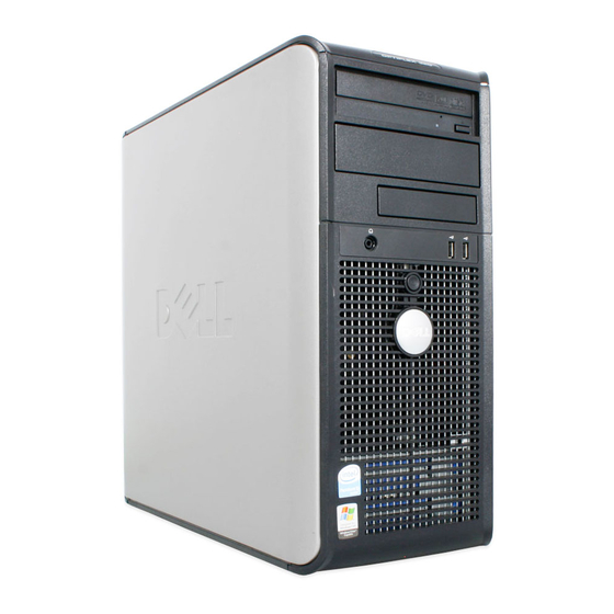
Page 14: System Views
System Views Mini Tower Computer — Front View Quick Reference Guide... - Page 15 optical drive Insert an optical drive (if supported) into this bay. (optional) floppy drive Can contain a floppy drive or a optional media card reader. bay (optional) USB 2.0 Use the front USB connectors for devices that you connect connectors (2) occasionally, such as joysticks or cameras, or for bootable USB devices ( "System Setup"...
- Page 16 power light The power light illuminates and blinks or remains solid to indicate different operating modes: • No light — The computer is turned off. • Steady green — The computer is in a normal operating state. • Blinking green — The computer is in a power-saving mode. •...
-
Page 17: Mini Tower Computer - Back View
Mini Tower Computer — Back View 1 cover release This latch allows you to open the computer cover. latch 2 padlock ring Insert a padlock to lock the computer cover. Quick Reference Guide... - Page 18 3 voltage selection Your computer may be equipped with a manual voltage- switch selection switch. To help avoid damaging a computer with a manual voltage selection switch, set the switch for the voltage that most closely matches the AC power available in your location. NOTICE: In Japan, the voltage selection switch must be set to the 115-V position even though the AC power...
-
Page 19: Mini Tower Computer - Back-Panel Connectors
Mini Tower Computer — Back-Panel Connectors 1 parallel connector Connect a parallel device, such as a printer, to the parallel connector. If you have a USB printer, plug it into a USB connector. NOTE: The integrated parallel connector is automatically disabled if the computer detects an installed card containing a parallel connector configured to the same address. - Page 20 3 network adapter To attach your computer to a network or broadband device, connector connect one end of a network cable to either a network jack or your network or broadband device. Connect the other end of the network cable to the network adapter connector on the back panel of your computer.
-
Page 21: Desktop Computer - Front View
9 serial connector Connect a serial device, such as a handheld device, to the serial port. The default designations are COM1 for serial connector 1 and COM2 for serial connector 2. For more information, see "System Setup Program" in your online User’s Guide. - Page 22 If your operating system has ACPI enabled, when you press the power button the computer will perform an operating system shutdown. Dell badge This badge can be rotated to match the orientation of your computer. To rotate, place fingers around the outside of the badge, press firmly, and turn the badge.
-
Page 23: Desktop Computer - Back View
hard-drive This light flickers when the hard drive is being accessed. activity light headphone Use the headphone connector to attach headphones and connector most kinds of speakers. microphone Use the microphone connector to attach a microphone. connector drive bay This bay accommodates an optional floppy drive, media card reader, or second hard drive. -
Page 24: Desktop Computer - Back-Panel Connectors
NOTE: 4 voltage selection Your computer may or may not have a voltage selection switch switch. Your computer may equipped with a manual voltage- selection switch. To help avoid damaging a computer with a manual voltage selection switch, set the switch for the voltage that most closely matches the AC power available in your location. - Page 25 1 parallel Connect a parallel device, such as a printer, to the parallel connector connector. If you have a USB printer, plug it into a USB connector. NOTE: The integrated parallel connector is automatically disabled if the computer detects an installed card containing a parallel connector configured to the same address.
-
Page 26: Small Form Factor Computer - Front View
6 line-in connector Use the line-in connector to attach a record/playback device such as a cassette player, CD player, or VCR. On computers with a sound card, use the connector on the card. 7 USB 2.0 Use the back USB connectors for devices that typically connectors (5) remain connected, such as printers and keyboards. - Page 27 If your operating system has ACPI enabled, when you press the power button the computer will perform an operating system shutdown. Dell badge This badge can be rotated to match the orientation of your computer. To rotate, place fingers around the outside of the badge, press firmly, and turn the badge.
- Page 28 power light The power light illuminates and blinks or remains solid to indicate different operating states: • No light — The computer is turned off. • Steady green — The computer is in a normal operating state. • Blinking green — The computer is in a power-saving mode.
-
Page 29: Small Form Factor Computer - Back View
Small Form Factor Computer — Back View 1 card slots (2) Access connectors for any installed PCI and PCI Express cards. 2 back-panel Plug serial, USB, and other devices into the appropriate connectors connectors (see "Small Form Factor Computer — Back- Panel Connectors"... -
Page 30: Small Form Factor Computer - Back-Panel Connectors
Small Form Factor Computer — Back-Panel Connectors 1 parallel Connect a parallel device, such as a printer, to the parallel connector connector. If you have a USB printer, plug it into a USB connector. NOTE: The integrated parallel connector is automatically disabled if the computer detects an installed card containing a parallel connector configured to the same address. - Page 31 3 network To attach your computer to a network or broadband device, adapter connect one end of a network cable to either a network jack or connector your network or broadband device. Connect the other end of the network cable to the network adapter connector on the back panel of your computer.
-
Page 32: Removing The Computer Cover
9 serial Connect a serial device, such as a handheld device, to the serial connector port. The default designations are COM1 for serial connector 1 and COM2 for serial connector 2. NOTE: There is only a serial connector 2 if the optional PS2/serial adapter is used. - Page 33 Hold a component such as a processor by its edges, not by its pins. NOTICE: Only a certified service technician should perform repairs on your computer. Damage due to servicing that is not authorized by Dell is not covered by your warranty. NOTICE: When you disconnect a cable, pull on its connector or on its strain-relief loop, not on the cable itself.
-
Page 34: Mini Tower Computer
Mini Tower Computer CAUTION: Before you begin any of the procedures in this section, follow the safety instructions in the Product Information Guide. CAUTION: To guard against electrical shock, always unplug your computer from the electrical outlet before removing the computer cover. 1 Follow the procedures in "Before You Begin"... - Page 35 1 security cable slot cover release latch padlock ring 4 computer cover Quick Reference Guide...
-
Page 36: Desktop Computer
Desktop Computer CAUTION: Before you begin any of the procedures in this section, follow the safety instructions in the Product Information Guide. CAUTION: To guard against electrical shock, always unplug your computer from the electrical outlet before removing the computer cover. 1 Follow the procedures in "Before You Begin"... - Page 37 1 security cable slot cover release latch padlock ring 4 computer cover Quick Reference Guide...
-
Page 38: Small Form Factor Computer
Small Form Factor Computer CAUTION: Before you begin any of the procedures in this section, follow the safety instructions in the Product Information Guide. CAUTION: To guard against electrical shock, always unplug your computer from the electrical outlet before removing the computer cover. 1 Follow the procedures in "Before You Begin"... -
Page 39: Inside Your Computer
1 security cable slot 2 cover release latch 3 padlock ring 4 computer cover Inside Your Computer Mini Tower Computer CAUTION: Before you begin any of the procedures in this section, follow the safety instructions in the Product Information Guide. CAUTION: To avoid electrical shock, always unplug your computer from the electrical outlet before removing the computer cover. - Page 40 NOTICE: Be careful when opening the computer cover to ensure that you do not accidentally disconnect cables from the system board. drive release latch optical drive floppy drive power supply chassis intrusion system board switch (optional) card slots (4) heat sink assembly hard drive front I/O panel Quick Reference Guide...
- Page 41 System Board Components speaker connector processor socket memory module (INT_SPKR) (CPU) connectors (DIMM_1, DIMM_2, DIMM_3, DIMM_4) power connector SATA drive SATA drive (PW_12V_A1) connectors (SATA2, connectors (SATA0, SATA3) SATA1) Quick Reference Guide...
- Page 42 front-panel power connector intrusion switch connector (POWER1) connector (FRONTPANEL) (INTRUDER) 10 CMOS reset jumper 11 battery socket 12 internal USB (USB1) (RTCRST) (BATTERY) 13 PCI Express x16 14 standby power 15 PCI connector connector (SLOT1) (AUX_PWR_LED) (SLOT2) 16 PCI Express x1 17 password jumper 18 PCI connector connector (SLOT4)
-
Page 43: Desktop Computer
Jumper Setting Description PSWD Password features are enabled (default setting). Password features are disabled. jumpered unjumpered Desktop Computer CAUTION: Before you begin any of the procedures in this section, follow the safety instructions in the Product Information Guide. CAUTION: To avoid electrical shock, always unplug your computer from the electrical outlet before removing the computer cover. - Page 44 1 drive release latch optical drive power supply 4 chassis intrusion system board card slots (3) switch (optional) 7 heat sink assembly front I/O panel Quick Reference Guide...
- Page 45 System Board Components speaker connector processor socket power connector (INT_SPKR) (CPU) (PW_12V_A1) memory module power connector SATA drive connectors (POWER1) connectors (SATA0, (DIMM_1, DIMM_2, SATA1, SATA2) DIMM_3, DIMM_4) Quick Reference Guide...
- Page 46 front-panel connector intrusion switch CMOS reset jumper (FRONTPANEL) connector (RTCRST) (INTRUDER) 10 battery socket 11 internal USB 12 PCI Express x16 (BATTERY) (USB1) connector (SLOT1) 13 standby power 14 PCI connectors 15 PCI Express (AUX_PWR_LED) (SLOT2, SLOT3) x1connector (SLOT4) 16 password jumper 17 floppy drive 18 serial connector (PSWD)
-
Page 47: Small Form Factor Computer
Jumper Setting Description PSWD Password features are enabled (default setting). Password features are disabled. jumpered unjumpered Small Form Factor Computer CAUTION: Before you begin any of the procedures in this section, follow the safety instructions in the Product Information Guide. CAUTION: To avoid electrical shock, always unplug your computer from the electrical outlet before removing the computer cover. - Page 48 1 drive release latch optical drive power supply 4 chassis intrusion hard drive card slots (2) switch (optional) 7 system board heat sink assembly front I/O panel System Board Components Quick Reference Guide...
- Page 49 fan connector processor socket power connector (FAN_CPU) (CPU) (PW_12V_A1) memory module power connector SATA drive connectors (POWER1) connectors (SATA0, (DIMM_1, SATA1) DIMM_2, DIMM_3, DIMM_4) front-panel fan connector intrusion switch connector (FAN_HDD) connector (FRONTPANEL) (INTRUDER) 10 CMOS reset jumper 11 battery socket 12 internal USB (USB1) (RTCRST) (BATTERY)
-
Page 50: Solving Problems
Solving Problems Dell provides a number of tools to help you if your computer does not perform as expected. For the latest troubleshooting information available for your computer, see the Dell Support website at support.dell.com. Quick Reference Guide... -
Page 51: Dell Diagnostics
If computer problems occur that require help from Dell, write a detailed description of the error, beep codes, or diagnostics light patterns, record your Express Service Code and Service Tag below, and then contact Dell from the same location as your computer. For information on contacting Dell, see your online User’s Guide. - Page 52 3 When the boot device list appears, highlight Boot to Utility Partition and press <Enter>. 4 When the Dell Diagnostics Main Menu appears, select the test you want to run. Starting the Dell Diagnostics From the Drivers and Utilities Media 1 Insert the Drivers and Utilities media.
- Page 53 Dell Diagnostics Main Menu 1 After the Dell Diagnostics loads and the Main Menu screen appears, click the button for the option you want. Option Function Express Test Performs a quick test of devices. This test typically takes 10 to 20 minutes and requires no interaction on your part.
-
Page 54: System Lights
4 When the tests are completed, if you are running the Dell Diagnostics from the Drivers and Utilities media (optional), remove the CD or DVD. 5 Close the test screen to return to the Main Menu screen. To exit the Dell Diagnostics and restart the computer, close the Main Menu screen. -
Page 55: Diagnostic Lights
Power Light Problem Description Suggested Resolution Solid yellow The Dell Diagnostics is If the Dell Diagnostics is running, running a test, or a device allow the testing to complete. on the system board may be See "Diagnostic Lights" on page 55... -
Page 56: Diagnostic Lights
To help you troubleshoot a problem, your computer has four lights labeled "1," "2," "3," and "4" on the front panel. The lights can be off or green. When the computer starts normally, the patterns or codes on the lights change as the boot process completes. - Page 57 • If the problem persists or the computer has integrated graphics, contact Dell for technical assistance. For information on contacting Dell, see your online User’s Guide. Quick Reference Guide...
- Page 58 • If available, install properly working memory of the same type into your computer. • If the problem persists, contact Dell for technical assistance. For information on contacting Dell, see your online User’s Guide. Quick Reference Guide...
-
Page 59: Beep Codes
• If the problem persists, contact Dell for technical assistance. For information on contacting Dell, see your online User’s Guide. A failure has occurred. • Ensure that the cables are properly connected to the... -
Page 60: Resolving Software And Hardware Incompatibilities
If your computer beeps during start-up: 1 Write down the beep code. 2 See "Dell Diagnostics" on page 51 to identify a more serious cause. 3 Contact Dell for technical assistance. For information on contacting Dell, see your online User’s Guide. -
Page 61: Restoring Your Operating System
Restoring Your Operating System The Microsoft Windows operating system provides System Restore to allow you to return your computer to an earlier operating state (without affecting data files) if changes to the hardware, software, or other system settings have left the computer in an undesirable operating state. See the Windows Help and Support Center for information on using System Restore. - Page 62 Windows XP Creating a Restore Point 1 Click the Start button and click Help and Support. 2 Click System Restore. 3 Follow the instructions on the screen. Restoring the Computer to an Earlier Operating State NOTICE: Before you restore the computer to an earlier operating state, save and close any open files and exit any open programs.
-
Page 63: Reinstalling Your Microsoft Windows Operating System
Undoing the Last System Restore NOTICE: Before you undo the last system restore, save and close all open files and exit any open programs. Do not alter, open, or delete any files or programs until the system restoration is complete. 1 Click the Start button, point to All Programs→... - Page 64 4 Restart the computer. When the DELL logo appears, press <F12> immediately. NOTE: If you wait too long and the operating system logo appears, continue ® ® to wait until you see the Microsoft Windows desktop; then, shut down your computer and try again.
- Page 65 The Operating System media provides options for reinstalling Windows XP. The options can overwrite files and possibly affect programs installed on your hard drive. Therefore, do not reinstall Windows XP unless a Dell technical support representative instructs you to do so.
- Page 66 4 If you want to install a new copy of Windows XP, press <Esc> to select that option. 5 Press <Enter> to select the highlighted partition (recommended), and follow the instructions on the screen. The Windows XP Setup screen appears, and the operating system begins to copy files and install the devices.
-
Page 67: Using The Drivers And Utilities Media
15 When the Ready to register with Microsoft? screen appears, select No, not at this time and click Next. 16 When the Who will use this computer? screen appears, you can enter up to five users. 17 Click Next. 18 Click Finish to complete the setup, and remove the media. 19 Reinstall the appropriate drivers with the Drivers and Utilities media. - Page 68 Reinstalling Drivers and Utilities NOTICE: The Dell Support website at support.dell.com and your Drivers and Utilities media provide approved drivers for Dell™ computers. If you install drivers obtained from other sources, your computer might not work correctly. Using Windows Device Driver Rollback...
- Page 69 Windows XP: 1 Click Start→ My Computer→ Properties→ Hardware→ Device Manager. 2 Right-click the device for which the new driver was installed and click Properties. 3 Click the Drivers tab→ Roll Back Driver. Manually Reinstalling Drivers After extracting the driver files to your hard drive as described in the previous section: Windows Vista: 1 Click Start...
- Page 70 6 Click Browse and browse to the location to which you previously copied the driver files. 7 When the name of the appropriate driver appears, click Next. 8 Click Finish and restart your computer. Quick Reference Guide...
-
Page 71: Index
38 beep codes, 59 removing, 32 system lights, 54 Dell Diagnostics, 51 hardware Dell support site, 9 beep codes, 59 diagnostics conflicts, 60 beep codes, 59 Dell Diagnostics, 51 Dell Diagnostics, 51 Hardware Troubleshooter, 60 documentation... - Page 72 System Restore, 61 operating system reinstalling, 8 Operating System CD, 8 troubleshooting beep codes, 59 conflicts, 60 Dell Diagnostics, 51 power Hardware Troubleshooter, 60 light, 22, 28 Help and Support Center, 10 restore to previous state, 61 power light system lights, 54...
- Page 73 User’s Guide, 6 warranty information, 6 Windows Vista Hardware Troubleshooter, 60 Help and Support Center, 10 reinstalling, 63 System Restore, 61 Windows XP Device Driver Rollback, 68 Hardware Troubleshooter, 60 Help and Support Center, 10 reinstalling, 8, 64 System Restore, 61 Index...
- Page 74 Index...
- Page 75 Dell™ OptiPlex™ 740 クイックリファレンスガイド DCSM DCNE DCCY モデル 、 、 w w w . d e l l . c o m | s u p p o r t . d e l l . c o m...
-
Page 76: Microsoft Windows
メモ、注意、警告 メモ 注意 警告 シリーズコンピュータをご購入いただいた場合、このマニュアルの Dell™ n ® ® オペレーティングシステムについての説明は適用されま Microsoft Windows せん。 ____________________ この文書の情報は事前の通知なく変更されることがあります。 すべての著作権は にあります。 © 2008 Dell Inc. の書面による許可のない複製は、いかなる形態においても厳重に禁じられています。 Dell Inc. 本書に使用されている商標: 、 、および のロゴは、 の商標です。 Dell OptiPlex DELL Dell Inc. 、 、 、および は、 Microsoft Windows... - Page 77 目次 ......... .
- Page 78 ......Dell Diagnostics ......
- Page 79 情報の検索方法 メモ メモ メディア • Drivers and Utilities メモ • Drivers and Utilities • • • DSS Drivers and Utilities Drivers and Utilities Dell Diagnostics Dell Diagnostics Readme メモ support.jp.dell.com...
- Page 80 製品情報ガイド • Dell™ • • • ユーザーズガイド • Dell™ OptiPlex™ • Microsoft Windows • • → Help and Start → Dell Support User and System Guides → System Guides Drivers and Utilities...
- Page 81 サービスタグおよび • ® ® ライセンス Microsoft Windows • Microsoft Windows • support.jp.dell.com •...
- Page 82 オペレーティングシステムメディア • メモ Microsoft Windows Drivers and Utilities Product key メモ...
- Page 83 デルサポートサイト • — Q&A — support.jp.dell.com • — メモ • — • — • — • support.jp.dell.com DSS — メモ support.jp.dell.com Dell™ Dell ® ® ヘルプとサポートセンター • Vista Windows Windows • Windows • • Windows Vista Start → Help and Support スタート...
- Page 84 コンピュータのセットアップ 警告 注意 注意 メモ...
- Page 85 注意 PS/2 注意 メモ...
- Page 86 注意 注意 100 V 115 V メモ 115 V...
- Page 88 システム表示 ミニタワーコンピュータ 正面図 —...
- Page 89 USB 2.0 注意 注意 ACPI...
- Page 90 • — • — • — • — Windows...
- Page 91 ミニタワーコンピュータ 背面図 —...
- Page 92 注意 100 V 115 V — PCI Express...
- Page 93 ミニタワーコンピュータ 背面パネルコネクタ — メモ こ 検 自 的 無 セ • — 10 Mbps • — 100 Mbps • — 1 Gbps 1000 Mbps • —...
- Page 94 メモ 10 Mbps 7 USB 2.0...
- Page 95 メモ ご購 こ キ キ 外 メモ ご COM1 COM2 デスクトップコンピュータ 正面図 —...
- Page 96 USB 2.0 注意 注意 ACPI • — • — • — • — Windows...
- Page 97 デスクトップコンピュータ 背面図 — PCI Express —...
- Page 98 メモ 注意 100 V 115 V デスクトップコンピュータ 背面パネルコネクタ — メモ こ 検 自 的 無 セ...
- Page 99 • — 10 Mbps • — 100 Mbps • — 1 Gbps 1000 Mbps • — メモ 10 Mbps 7 USB 2.0...
- Page 100 メモ ご購 こ キ キ 外 メモ ご COM1 COM2 メモ PS2/ ん スモールフォームファクターコンピュータ 正面図 —...
- Page 101 USB 2.0 注意 順 注意 ACPI...
- Page 102 • — • — • — • — Windows...
- Page 103 スモールフォームファクターコンピュータ 背面図 — PCI Express — 注意 100 V 115 V...
- Page 104 スモールフォームファクターコンピュータ 背面パネルコネクタ — メモ こ 検 自 的 無 セ • — 10 Mbps • — 100 Mbps • — 1 Gbps 1000 Mbps • — メモ 10 Mbps...
- Page 105 7 USB 2.0 メモ ご購 こ キ キ 外 メモ ご COM1 COM2 メモ PS2/ ん コンピュータカバーの取り外し 警告 警告...
- Page 106 作業を開始する前に 注意 べ 存 閉 中 べ 終了 Start Shutdown Shutdown Shutdown コンピュータ内部の作業を始める前に 警告 警告 注意 修理 資格 技術者 み 許 修理 証 ん 注意 外 分 ち 自身 引 こ こ 外 込ん 抜 抜 際 曲 引 抜 際...
- Page 107 警告 • • • 注意 触 金 塗 金 触 身体 静 除去 中 期 的 塗 金 触 静 除去 ミニタワーコンピュータ 警告 警告...
- Page 108 セキ...
- Page 109 デスクトップコンピュータ 警告 警告...
- Page 110 セキ...
- Page 111 スモールフォームファクターコンピュータ 警告 警告 警告...
- Page 112 セキ コンピュータ内部 ミニタワーコンピュータ 警告 警告 注意 際 基板 外 こ 意...
- Page 113 光学 基板 ヒ セ...
- Page 114 システム基板のコンポーネント INT_SPKR DIMM_1 DIMM_2 DIMM_3 DIMM_4 SATA SATA PW_12V_A1 SATA2 SATA0 SATA1 SATA3 FRONTPANEL POWER1 INTRUDER...
- Page 115 10 CMOS USB USB1 RTCRST BATTERY 13 PCI Express x16 15 PCI SLOT1 AUX_PWR_LED SLOT2 16 PCI Express x1 18 PCI SLOT4 PSWD SLOT3 DSKT PS2/SER2 DVI_HDR FAN_CPU ジャンパ設定 PSWD 有効 無効...
- Page 116 デスクトップコンピュータ 警告 警告 注意 際 基板 外 こ 意 光学 基板 ヒ セ...
- Page 117 システム基板コンポーネント INT_SPKR PW_12V_A1 SATA DIMM_1 POWER1 SATA0 DIMM_2 DIMM_3 SATA1 SATA2 DIMM_4 CMOS FRONTPANEL RTCRST INTRUDER 12 PCI Express x16 USB USB1 BATTERY SLOT1...
- Page 118 14 PCI 15 PCI Express x1 AUX_PWR_LED PSWD DSKT PS2/SER2 FAN_CPU DVI_HDR ジャンパ設定 PSWD 有効 無効...
- Page 119 スモールフォームファクターコンピュータ 警告 警告 注意 際 基板 外 こ 意 光学 基板 ヒ セ...
- Page 120 システム基板コンポーネント...
- Page 121 FAN_CPU PW_12V_A1 SATA DIMM_1 POWER1 SATA0 DIMM_2 SATA1 DIMM_3 DIMM_4 FRONTPANEL FAN_HDD INTRUDER 10 CMOS USB USB1 RTCRST BATTERY 14 PCI Express x16 15 PCI AUX_PWR_LED SLOT1 SLOT2 PSWD PS2/SER2 DSKT INT_SPKR DVI_HDR...
- Page 122 ジャンパ設定 PSWD 有効 無効...
- Page 123 問題の解決 support.jp.dell.com ___________________________ :___________________________ (診断)プログラム Dell Diagnostics 警告 (診断)プログラムを使用する場合 Dell Diagnostics Dell Diagnostics 注意 上 み Dell Diagnostics Dell™ Drivers and Utilities Dell Diagnostics...
- Page 124 (診断)プログラムをハードディスクドライブから起動する場合 Dell Diagnostics Dell Diagnostics メモ へ DELL™ <F12> メモ 見 こ 知 セ Drivers and Utilities Dell Diagnostics ® ® Microsoft Windows Boot to Utility Partition <Enter> Dell Diangnostics Main Menu (診断)プログラムを メディアから起動する Dell Diagnostics Drivers and Utilities 場合...
- Page 125 32 Bit Dell Diagnostics Dell Diagnostics Main Menu (診断)プログラムのメインメニュー Dell Diagnostics Dell Diagnostics Main Menu Express Test 実行 ~ 分 操 何 初 Express Test 実行 素早 特 増 Extended Test 体 実行 間 上 期的 質 答 Custom Test 特...
- Page 126 Results 結果 発 表 Errors 検 表 Help 実行 件 Configuration 選択 ェ 構成 表 Dell Diagnostics 各 部 構 成情報 得 画 左 表 覧 名 名 表 限 Parameters 変更 Dell Diagnostics Drivers and Utilities Main Menu Dell Diagnostics Main Menu システムライト...
- Page 127 Dell Diagnostics Dell Diagnostics 実行中 実行中 ば 終了 待 板 不良 正 特 識別 認 連絡 板 障害 発 特 識別 認 中 実行中 検 POST BIOS 特 識別 認 中 POST 不良 正 特 識別 表 認 板 欠陥...
- Page 128 診断ライト 警告 POST POST メモ 向 縦向 横向 ち 障害 BIOS 正 障害 発 BIOS BIOS Recovery Utility 修 実行 修 処 完了 BIOS 待 障害...
- Page 129 検 • 障害 発 • • • 障害 • 発 • •...
- Page 130 障害 発 障害 発 認 検 • • • •...
- Page 131 検 特別 • 件 存在 • • 障害 発 • 表 • • 終了 特 POST 短 間 消 ビープコード Dell Diagnostics...
- Page 132 ェ BIOS 失敗 変更 不具 <F12> ソフトウェアおよびハードウェアの非互換性の解決 Windows Vista Start Help and Support hardware troubleshooter <Enter> Windows XP → ハードウェアに関するトラブルシューティング <Enter>...
- Page 133 お使いのオペレーティングシステムの回復 Microsoft Windows Windows 注意 期的 成 元 変更 監視 元 こ ん Windows Vista Start Start Search System Restore <Enter> メモ User Account Control こ 管理者 管理者 Continue 管理者 希望 Next 注意 元 消 べ 存 閉 中 べ 終了 元...
- Page 134 Windows XP 注意 状態 元 べ 存 閉 中 べ 終了 元 完 了 変更 削除 → → 注意 元 消 べ 存 閉 中 べ 終了 元 完了 変更 削 除 → →...
- Page 135 200 MB Windows XP お使いの オペレーティングシステムの再インス Microsoft Windows トール Windows Vista Windows のインストール Exit DELL <F12> メモ キ 遅 ゴ ® ® Microsoft Windows 待ち 試み...
- Page 136 必 XP Service Pack 1 Windows XP Windows XP Windows 注意 上 べ 成 標準的 構成 番 識 Windows XP • Dell™ • Dell Drivers and Utilities メモ 造工程 Drivers and Utilities 収録 Drivers and Utilities 必 べ Windows XP...
- Page 137 影響 与 こ 理由 担当者 指 限 Windows XP 注意 拮抗 Windows XP 無 Windows XP 順 Windows XP 終了 DELL™ <F12> Windows CD-ROM <Enter> CD から起動する場合は、いずれかのキーを押してください Windows XP Windows XP <Enter> Microsoft Windows <F8> Windows XP Windows XP Windows XP <Esc>...
- Page 138 注意 セ キ Press any key to boot from the CD. メモ 容量 速 セ 間 Administrator Windows XP Professional Windows XP 注意 セ キ Press any key to boot from the CD. Microsoft Windows インターネットに接続する方法を指定してください Microsoft...
- Page 139 Drivers and Utilities メモ Microsoft Office Microsoft Works Suite Microsoft Office Microsoft Works Suite 裏 キ 必 Product Key メディアの使い方 Drivers and Utilities 注意 Drivers and Utilities 収録 こ Microsoft Windows • • • ドライバの識別 Windows Vista® Start Computer → Properties Device Manager メモ...
- Page 140 Windows® XP → ドライバとユーティリティの再インストール 注意 support.jp.dell.com Drivers and Utilities 承 済み 提供 Dell™ 媒体 こ Windows Windows Windows Vista Start Computer → Properties Device Manager メモ User Account Control こ 管理者 管理者 Continue 管理者 起 Properties → Drivers Roll Back Driver Windows XP →...
- Page 141 Windows Vista Start Computer → Properties Device Manager メモ User Account Control こ 管理者 管理者 Continue 管理者 起 Audio Video → → Driver Update Driver Browse my computer for driver software Browse → → Next Finish Windows XP → → →...
- Page 143 索引 , 132 , 83 , 82 あ Dell Diagnostics , 123 Diagnostics , 131 え Dell Diagnostics , 123 , 126 Drivers and Utilities CD , 79 , 131 , 132 お , 82 Windows Vista CD , 82...
- Page 144 き と , 140 , 132 , 139 Dell Diagnostics , 123 こ , 126 , 133 , 132 , 131 , 83 さ , 133 , 132 , 81 Windows Vista , 135 に Windows XP , 136 , 80...
- Page 145 ふ ら , 133 , 126 , 96, 102 , 106 Microsoft Windows , 81 , 81 へ , 83 Windows , 83 ま , 80 , 83 , 80 , 80 , 80 , 80 も ゆ , 80 索引...
- Page 146 索引...