
Related Manuals for JR X9503 2.4


Summary of Contents for JR X9503 2.4
- Page 1 X9503 2.4 9-CHANNEL, 50-MODEL MEMORY COMPUTER RADIO SYSTEM WITH SPEKTRUM 2.4GHz DSM TECHNOLOGY INSTRUCTION AND PROGRAMMING MANUAL...
-
Page 2: Table Of Contents
Access the System Menu ..........................A-2 Using the Included Charger ........................G-12 Select a Model Memory ..........................A-2 X9503 2.4 Transmitter Features (Mode 2 Airplane Shown) ...............G-13 Reset The Model ..............................A-3 X9503 2.4 Transmitter Features (Rear) ....................G-14 To Activate the ACRO Mode ........................A-4 Battery Cover ............................G-14... - Page 3 Transfer – Transfer the Model to Another Transmitter or to DataSafe ..........H-7 Rudder-to-Throttle Mixing .........................H-30 Transfer a Model From the X9503 2.4 – (Transfer function) – To Send ..........H-7 Accessing the Cyclic-to-Throttle Function ..................H-31 Transfer a Model to the X9503 2.4 – (Transfer function) – To Receive ..........H-8...
- Page 4 Trainer – Programmable Trainer System....................S-36 X9503 2.4 Used as Master (Instructor) – (Trainer System) ............H-44 X9503 2.4 Used as Master (Instructor) – (Trainer System) ............S-36 X9503 2.4 Used as Slave (Student) – (Trainer System) ..............H-45 X9503 2.4 Used as Slave (Student) – (Trainer System) ..............S-37 Timer –...
-
Page 5: Section 1: Using The Manual
JR X9503 Transmitter Step #35 Aileron Differential ........................S-64 Flaperon Mix ............................... S-65 JR’s X9503 2.4 offers airplane, helicopter and sailplane safety. Now with even the most sophisticated models Flaperon Mix ............................... S-65 pilots sophisticated programming that JR’s 9303 is up to 9 channels, you’ll no longer have to wait for an... -
Page 6: Jr R921 Receiver
Section 3: Component Specifications JR R921 Receiver The R921 receiver combines two internal with one or to a different RF environment creating a superior RF Charger Specifications two (optional) remote receivers, offering superior path link in all conditions. The JR R921 allows the use diversity. The radio system simultaneously transmits of an optional Flight Log Data Recorder (JRPA145) to Model Number AD35M05 on two frequencies, creating up to four RF paths on two be used. The Flight Log plugs into the data port and Input Voltage AC 120V, 60Hz... -
Page 7: Battery Charging
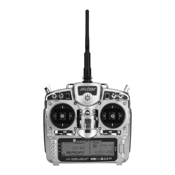
Battery Charging X9503 2.4 Transmitter Features (Mode 2 Airplane Shown) Transmitter/Receiver Note: You should fully charge both the transmitter and the receiver battery packs prior to each flying Mix Switch session. Also, check the condition of the receiver AUX2 battery between each flight using a reliable battery... - Page 8 X9503 2.4 Transmitter Features (Rear) X9503 2.4 Transmitter Features (Internal) AILERON TENSION SCREW THROTTLE TENSION SCREW Model No. X9503 DC 11.6V U.S. Patent 7,391,320 Horizon Hobby, Inc. Made in Malaysia ELEVATOR TENSION SCREW RUDDER TENSION SCREW Back of Transmitter (Mode 2) Control Stick Tension Adjustment Remove the six transmitter screws from the back cover as Adjust each gimbal tension screw for desired tension shown on page G-14. Remove the transmitter back, being...
-
Page 9: Advanced Digital Trims
Advanced Digital Trims Installing the Receiver The X9503 2.4 features Advanced Digital Trims. On the By using the Trim Step Function located in the System Installing the JR R921 Mounting the remote receiver(s) in a different Normal display screen, if a trim lever is moved, the screen Mode, you can adjust the amount of travel per each trim location(s) from the primary receiver, gives tremendous will automatically change to display the graphic position step for your specific application. - Page 10 Binding In helicopters, there is generally enough room on Other Important Installation Tips It’s necessary to program the receiver to the transmitter 3. Establish the desired fail-safe stick positions: normally the servo tray to achieve the necessary separation. If so that the receiver will only recognize that specific low throttle and flight controls neutral.
-
Page 11: Features
Range Testing the X9503 2.4 their preset fail-safe positions, normally control surfaces aircraft from flying away. When the signal is regained, the 3. You should have total control of the model with the at neutral and the landing gear down. These fail-safe... -
Page 12: Advanced Range Testing Using A Flight Log
20. 6. After one minute, release the bind button. A successful range check will have recorded zero frame losses. Advanced Range Testing the X9503 2.4 A hold occurs when 45 continuous (one right after the Scroll the Flight Log through the Antenna fades other) frame losses occur. -
Page 13: Recommended Power System Guidelines
Receiver Power System Requirements Flash Memory With all radio installations, the onboard power system 2. With the current meter inline with the receiver battery All preprogrammed data is protected by a flash must provide adequate power without interruption to the lead, load the control surfaces (apply pressure memory that guards against memory loss . with your hand) while monitoring the current. The receiver even when the system is fully loaded (servos at maximum flight loads). This becomes especially critical maximum continuous recommended current for a... -
Page 14: Modelmatch
Tips on Using 2.4GHz Systems (continued) 3. Q: I’ve heard that the DSM system is less tolerant of 5. Q: Can I use a 3-cell Li-Po pack in my transmitter? low voltage. Is that correct? A: No. All current JR and Spektrum transmitters are A: All DSM receivers have an operational voltage range designed to operate using a 9.6-volt transmitter pack. of 3.5 to 9 volts. With most systems, this is not a A fully charged 3-cell Li-Po pack puts out 12.6 volts. problem as most servos cease to operate at around This higher voltage can overload the power-regulating 3.8 volts. When using multiple high-current draw transistor causing damage and or failure, possibly servos with a single or inadequate battery/power in flight. Many of our customers have experienced source, heavy momentary loads can cause the failures using 3-cell Li-Po packs and their use in JR voltage to dip below this 3.5-volt threshold, causing... -
Page 15: Airplane - Acro Mode
AIRPLANE – ACRO MODE Flight Modes The ACRO mode of the X9503 2.4 system is intended for The X9503 2.4 provides the ability to combine many of the powered fixed-wing aircraft. It contains a host of advanced above functions during flight, using a single Flight Mode features that are easy to set up and use, and are designed switch. -
Page 16: Access The System Menu
ACCESS THE SYSTEM MENU RESET THE MODEL 1. To access the System menu [SYSTEM M.], hold When setting up a new model you should reset all 1. In the SYSTEM Menu, highlight and select MDL down the ENT button while turning the transmitter on. parameters to their default or factory settings before Reset using the Selector. -
Page 17: To Activate The Acro Mode
SYSTEM Menu that control some of the more (Normal, Flaperon, Delta); program the aircraft’s tail advanced features of the X9503 2.4 system. Use the configuration; and identify any dual channels for primary 2. Highlight and select ACRO using the Selector. -
Page 18: Flight Modes
An aerobatic aircraft, for example, may be set up such that the Flight Mode switch in its Many of the functions found in the X9503 2.4 system first position configures the aircraft for normal precision are switch selectable (including programmable mixers) flying. -
Page 19: Trim:com (Flight Modes
TRIM:COM (Flight Modes) SWITCH ASSIGNMENTS The X9503 2.4 provides the ability to change the standard 1. From within the Devic.SEL function, use the Selector You can toggle the TRIM:COM parameter back and forth If Flight Modes are only going to be used to switch... -
Page 20: Activate/Inhibit Switches
ACTIVATE/INHIBIT SWITCHES WING TYPE The X9503 2.4 provides the ability to inhibit or otherwise 1. If you will use GEAR, FLAP, AUX2, AUX3, or The Wing Type function provides 3 different wing types The Wing Type function also provides for aircraft that... -
Page 21: Wing Parameter - (Wing Type
WING Parameter – (Wing Type) WING Parameter – (Wing Type) (continued) 1. Highlight and select Wing TYPE in the SYSTEM parameter set to the default of NORMAL and plug 4. If the aircraft is a Delta wing configuration, highlight Note: To properly set the servo direction when Menu using the Selector. -
Page 22: V-Tail (Wing Type
V-tail (Wing Type) V-tail (Wing Type) (continued) 1. If the aircraft has a V-tail configuration, highlight INH Note: To properly set the servo direction when 2. Highlight and select the channel that is to be the Mate 3. If FLAP or AUX3 is selected as a Mate, INH next to V-tail in the Wing TYPE function and press the using the V-tail setting, begin by using servo (slave) to the control channel represented above it. -
Page 23: Twin E. (Wing Type
Twin E. (Wing Type) Twin E. (Wing Type) (continued) If the aircraft is equipped with twin engines, you can use 1. Highlight and select INH next to Mate under Twin E. 3. If you select FLAP or AUX3 as the Mate and will the Twin Engine feature (Twin E.) for a 2nd throttle channel A list of available channels appears. -
Page 24: Trim Step
After defining the basic aircraft configuration in the The descriptions are general in nature and are intended to X9503 2.4 trim levers and switches. It allows quick an aircraft in order to trim the aircraft quickly. Then use a SYSTEM Menu, use the functions in the Function List... -
Page 25: Sub Trim
Sub-Trim TRVL ADJ. – TRAVEL ADJUST Use Sub-Trims for minor adjustments to servo linkages, Use Sub-Trims to fine-tune the alignment of servo arms. Use Travel Adjust to calibrate how far a servo travels in each 1. Highlight and select TRVL ADJ. in the FUNC.LIST not for major trim adjustments to the aircraft. -
Page 26: D/R & Exp - Dual Rate And Exponential
D/R & EXP – DUAL RATE AND EXPONENTIAL THRO CURV – THROTTLE CURVE Dual Rates and Exponential curves can be very effective and your desired response from the aircraft. For an A linear throttle response can be obtained with the THRO If you activated the Twin E. -
Page 27: Flap Sys. - Flap System
The Delay determines how long it takes for the Flaps and OUT line under FLAP in the Devic. SEL function within the Elevator to reach their positions. The X9503 2.4 ensures that SYSTEM Menu. the Flaps and Elevator reach their positions at the same time resulting in smooth Flap deployment and retraction. -
Page 28: Auto Land (Flap System
AUTO LAND (Flap System) ELEV – ELEVATOR COMPENSATION (Flap System) The Auto Land feature, if implemented, automatically Highlight and select FLAP SYS. in the FUNC.LIST to The ELEV values represent the Elevator deflection that 2. Scroll to the Mid parameter beside ELEV and select it. retracts the Flaps and Elevator compensation when the obtain the Flap System display if the aircraft has flaps or occurs when the Flaps are deployed to their various... -
Page 29: Flap - (Flap System
FLAP – (Flap System) FM0-FM2 (Flap System) The FLAP values represent how far the flaps deflect when 1. Put the Flap switch in its uppermost (Normal) position If Flight Modes have been activated in the Devic. SEL in the NORM, Mid, and Land positions. The NORM (no flaps deployed). -
Page 30: Delay (Flap System)
The Delay parameter determines how long it takes for 1. Highlight and select Delay in the Flap System The X9503 2.4 features a built-in mixer for Elevator-to- flaps travel up with up elevator and down with down the flaps and Elevator to reach their positions. The display using the Selector. -
Page 31: Ail Diff. – Aileron Differential
RUD M – AILERON-TO-RUDDER MIXING AIL DIFF. – AILERON DIFFERENTIAL The X9503 2.4 features a built-in mixer for Aileron-to- be made to move in either direction by using positive or When Ailerons are deflected, the Aileron that deflects To use the Aileron Differential function, highlight and Rudder. -
Page 32: Srv. Speed – Servo Speed
60 degrees of rotation all the way up to 15 seconds for 60 degrees of rotation. Adjust the speed The X9503 2.4 has a Snap Roll system comprised of a of each servo until the desired speed is obtained. -
Page 33: Snap Roll
Snap Roll switch used in conjunction with Flight Modes to Roll in the FUNC.LIST, then select INH to activate it. The X9503 2.4 features a very sophisticated Gyro Gain You can use up to 2 gyros to control two of the three... -
Page 34: Fixed Gyro Gain (Gyro System)
FIXED GYRO GAIN (Gyro System) STICK OVERRIDE GYRO GAIN (Gyro System) Fixed Gyro Gain does not use the Stick Override Gain 2. Decide which switch will control gyro gain. The Flap Stick Override Gyro Gain is very popular with aerobatic Stick Override Gyro Gain is identical to Fixed Gyro Gain feature. -
Page 35: Prog Mix – Programmable Mixers
PROG MIX – PROGRAMMABLE MIXERS STANDARD PROGRAMMABLE MIXER – Example: DOWN ELEVATOR AT IDLE The X9503 2.4 System provides 4 Standard direction of the Rudder in order to keep the aircraft Perhaps the best way to describe a Programmable The Mix parameters will be selected and set in the programmable mixers (PROG.MIX3 - PROG.MIX6) and 2... -
Page 36: Multi-Point Mixer – Example: Eliminate Pitch-Coupling
STD PROGRAMMABLE MIXER – Ex: DOWN ELEV AT IDLE (continued) MULTI-POINT MIXER – Example: ELIMINATE PITCH-COUPLING The Elevator should move slightly downward when the 8. Verify Operation. Highlight and select the position The example below demonstrates a Multi-Point Program The Mix parameters will be selected and set in the throttle is set to idle. -
Page 37: Trainer – Trainer System
The Elevator should deflect deflection until the aircraft no longer pitches during knife- The X9503 2.4 is now ready to be used as the Master default MASTER mode. Up when the Rudder is moved in both directions. If edge. -
Page 38: X9503 2.4 Used As Slave (Student) – (Trainer System)
Timer display. If the master system is an XP9303, X9303 2.4, X9503 2.4, The X9503 2.4 is now ready to be used as the Slave or when active and can be started, stopped and reset from or 12X and the individual channels are not selected in the student transmitter. -
Page 39: Monitor
The Monitor function displays each channel and shows 1. To access the Monitor function, highlight and The X9503 2.4 System includes two utility functions to the movement of channels when sticks, levers and select MONITOR in the FUNC.LIST to obtain help with managing the settings programmed into the switches are moved. -
Page 40: Receive A Model Into The X9503 2.4 – (Transfer Function)
SYSTEM Menu. Then highlight and select and can copy the contents of a model memory to another X9503 2.4 transmitter. It is also used to receive data for a Select to obtain the Copy display. model, from another X9503 2.4 transmitter. -
Page 41: Receive A Model Into The X9503 2.4 – (Transfer Function)
RECEIVE A MODEL INTO THE X9503 2.4 – (Transfer function) Sub-Trim USAGE AND MECHANICAL ADVANTAGE 1. Hold the ENT button while plugging the trainer cord described above. Sub-Trim into the back of the transmitter to obtain the SYSTEM 2. Highlight and select TRANSFER in the SYSTEM... - Page 42 DUAL RATES AND EXPONENTIAL CURVES Setup Sheet (Aircraft) Dual Rates and Exponential curves can be very effective When using Exponential, a positive (+) exponential in setting up an aircraft to “feel” the way you would like percentage causes the servo to move less when the stick it to feel when performing different types of maneuvers.
- Page 43 A-56...
-
Page 44: X9503 2.4 Helicopter – Heli Mode
• Throttle Curves (up to 5) with up to 7 Points • Pitch Curves (up to 6) with up to 7 Points The Heli mode of the X9503 2.4 system is intended for • Gyro System (In Flight Gain Selection of... -
Page 45: Model Sel- Model Selection
ACCESS THE SYSTEM MENU Copy – Copying the Currently Selected Model to Another Model Memory 1. Bring up the SYSTEM Menu by holding down the The Copy function is part of the Model SEL function Making a backup copy protects you from losing the ENT button while turning the transmitter on. -
Page 46: Data Reset – Reset The Model
COPY. The entire contents of the currently Note: As the X9503 2.4 has the ModelMatch feature, selected model copy to the lower model on the display in order to operate the receiver on a new model... -
Page 47: Mdl Name-Enter A Name For The Model
X9503 2.4 transmitter. 1. In the SYSTEM Menu, highlight and select Type 3. Return to the SYSTEM Menu by pressing the TRANSFER A MODEL FROM THE X9503 2.4 – (Transfer function) – To Send SEL using the Selector. LIST button. -
Page 48: Transfer A Model To The X9503 2.4 – (Transfer Function) – To Receive
TRANSFER A MODEL TO THE X9503 2.4 – (Transfer function) – To Receive TRIM STEP 1. Hold the ENT button while plugging the trainer cord 2. Highlight and select TRANSFER in the SYSTEM Menu The Trim Step function provides for adjusting the... -
Page 49: Heli - System Menu - Advanced Functions
The X9503 2.4 offers the pilot up to 6 separate flight To Activate 2 Additional Flight Modes modes. The X9503 2.4 is factory preset to offer the pilot 4 (Flight Modes 3 and 4) separate Flight Modes (N, 1, 2, H). There are 2 additional 1. -
Page 50: Activate/Deactivate Switches
ACTIVATE/DEACTIVATE SWITCHES SWASH TYP-SWASHPLATE TYPE The X9503 2.4 provides the ability to disable a number of 1. If using PIT TRIM, GEAR, AUX2, AUX3, or AUX4 as a The Swashplate Mixing function enables the X9503 2.4 The Swashplate options are: the switches on the transmitter –... -
Page 51: Function Mode
FUNCTION MODE Auto Dual Rate HELI – FUNCTION LIST The Automatic Dual Rate function allows you to change To access the Auto D/R feature, roll the selector to the the dual rate and expo values of the elevator, aileron, and right until the D/R Expo graph is replaced by the Auto D/R Once you’ve setup the SYSTEM settings, use the The descriptions are general in nature and are intended to... -
Page 52: Trvl Adj. - Travel Adjust
Sub-Trim TRVL ADJ. – TRAVEL ADJUST You should use Sub-Trims for minor adjustments to servo Use Sub-Trims to fine-tune the alignment of servo arms. Use Travel Adjust to alter how far a servo travels in each 1. Highlight and select TRVL ADJ. in the FUNC.LIST linkages, not for major trim adjustments. -
Page 53: Swash Mix- Ccpm Swashplate Mixing
This exponential removes the non-linear, or rough Accessing the Swashplate Mixing Function Swashplate mixing. If you have not activated CCPM 2.4 allows you to use the X9503 2.4 in helis that utilize movement of the swashplate due to the mechanical 1. Turn the transmitter ON. -
Page 54: Thro Hold- Throttle Hold
THRO HOLD- THROTTLE HOLD Stick Auto/Auto Cut Setting The Throttle Hold function holds the throttle servo in Accessing the Throttle Hold Function The Stick Auto Setting acts as an automatic Throttle cutoff To activate the Stick Auto function, highlight the Stick a specific position during an autorotation. -
Page 55: Thro Curv - Throttle Curves
THRO CURV – THROTTLE CURVES Accessing the Throttle Curve Function The X9503 2.4 offers up to five (5) separate throttle curves Use positions 1 and 2 (Stunt 1 and Stunt 2) for aerobatic 1. Turn the transmitter ON. 4. Highlight the desired throttle point to be adjusted. -
Page 56: Throttle Trim Lever Function
Note: In each curve, the factory setting indicates Throttle Curve Exponential With the X9503 2.4 system, individual throttle curves Accessing the Throttle Curve Exponential INH for points 1, 2, 4 and 5. These values are To keep this from happening, highlight each point and... -
Page 57: Hovering Pitch Lever
0 to 100 to of the REVO.MIX on the top of the LCD to same time. The X9503 2.4 offers two separate revolution ease your understanding of other curves. indicate the current throttle stick/mix position mixing programs, with independent up and down mixing (U for Up, D for Down). -
Page 58: Gyro Sens/Gyro Gain Function
GYRO SENS/Gyro Gain Function Gyro Remote Gain Connections: JR G500T, JR770 and Others The X9503 2.4 offers two different types of Gyro Gain If you select manual mode (RUDD D/R), you must use Sensitivity Adjustments: manual or automatic. This the Rudder D/R switch to make gain changes. -
Page 59: Rudder-To-Throttle Mixing
A + value increases throttle; a – value decreases throttle. Setting the Desired Flight Modes for Cyclic-to-Throttle Mixing The X9503 2.4 allows you to select the specific Flight 6. Press the Selector to open the Flight Mode options box. Highlight the desired flight mode to be modes when the Cyclic-to-Throttle Mixing is active. -
Page 60: Governor- Governor Function
2. Press the LIST key to enter Function mode. You can use the X9503 2.4’s Governor function with most switch or lever on the Master channel and the transmitter sticks used to turn a mixer on and off. You can select and 3. -
Page 61: Prog Mix 1-6 – Programmable Mixes 1 Through 6
PROG MIX 1-6 – PROGRAMMABLE MIXES 1 through 6 (continued) Swashplate Timing Mixes Example: Elevator-to-Aileron (Corrects Vertical Tracking) • Eliminate Pitch to Collective Trim Changes • Activating Retractable Gear via the Flight The example below demonstrates a program mix for a heli Select and set the mix parameters in the following order: (non CCPM only) Mode switch... -
Page 62: Swashplate Timing: Aileron-To-Elevator (Corrects Rolling Maneuvers)
Swashplate Timing Mixes (continued) Swashplate Timing: Aileron-to-Elevator (Corrects Rolling Maneuvers) 4. Travel and Direction. Highlight POS 1 with the If an Elevator-to-Aileron mixing value is also required This mix functions and is set up as described in the Highlight and select one of the Standard Programmable Selector and press to access the values. -
Page 63: Standard Programmable Mixes – Example: Right Aileron With Positive Pitch
Swashplate Timing: Aileron to Elevator (continued) STANDARD PROGRAMMABLE MIXES – Example: Right Aileron with Positive Pitch 1. Select Master. All Programmable Mixers default 3. Select Position and Flight Modes. Move the Selector The example below demonstrates a program mix for a Mix Position and Flight Mode. -
Page 64: Multi-Point Mixes – Example: Fmod To Gear Mixing (Retract And Other Functions)
STANDARD PROGRAMMABLE MIXES – Example: Right Aileron with Positive Pitch (continued) MULTI-POINT MIXES – Example: FMOD to Gear Mixing (Retract and other Functions) 2. Select Master. All Programmable Mixers default 4. Select Position and Flight Modes. Move the Selector The example below demonstrates a Multi-Point 1. - Page 65 MULTI-POINT MIXES – FMOD to Gear (continued) MULTI-POINT MIXES – FMOD to Gear (continued) 4. Select switch. Scroll down, highlight, and press SW 5. Set Points for Travel and Direction. Seven points will 8. Verify Operation. Power up the receiver, making sure SELECT.
-
Page 66: Trainer – Programmable Trainer System
2. Make sure the Slave transmitter is in the PPM/FM switch transfers control to the student when the X9503 2.4 system is an XP9303, X9303 2.4, X9503 2.4, or 12X and modulation mode. If the slave system is a X9503 2.4 or is being used as the Master/Instructor transmitter. -
Page 67: Timer – Timer System
Timer – Timer System MONITOR- SERVO MONITOR The X9503 2.4 contains a Timer System with two timers. an Auto Start function is available that will start the timer The Servo Monitor function displays each channel and CH-6. It is a handy way to determine what channels are... -
Page 68: Setup Sheet (Helicopter)
Setup Sheet (Helicopter) MODEL NO MODEL NAME SPOI AIL1 ELEV RUDD AIL2 FLAP AUX2 AUX3 NORM NORM NORM NORM NORM NORM NORM NORM REVERSE SW SUB-TRIM TRAVEL ADJUST AILE ELEV RUDD POS0 ACT INH AUTO POS1 ACT INH POS2 ACT INH DUAL RATE/EXP AUX2 HOLD PIT INH... -
Page 69: Sailplane – Glid Mode
Sailplane – GLID Mode The GLID mode is intended for multi-function sailplanes. • Aileron and Flap Differential–Separate differential Up to 5 flight modes are available, each allowing virtually values (5) are available in each flight mode every parameter to be individually adjusted. Active including reverse differential (for landing). -
Page 70: System Mode
System Mode Model Select System mode is the foundational programming. The To enter System Mode: Model select allows you to store and select up to 50 1. In the , highlight and select SYSTEM Menu Model SEL screens include model name, model reset, modulation, different models. - Page 71 . The entire contents of COPY The display shows the currently selected model on top Note: Since the X9503 2.4 has ModelMatch, in the currently selected model copy to the lower model with a down arrow pointing to the lower model memory.
-
Page 72: Model Name
Model Name Model Reset To easily identify a model or the channel it’s on, the model 2. The cursor appears at the beginning of the model name. Model Reset returns the program to the factory default 1. In the , highlight and select SYSTEM Menu MDL Reset name screen allows you to give each model an 8-digit... -
Page 73: Model Select
TRANSFER – Transfer the Model to Another Transmitter TRANSFER a Model to the X9503 2.4 – (Transfer function) The TRANSFER function is in the SYSTEM Menu and Note: The receiving transmitter must be an X9503 1. Hold the ENT button while plugging the trainer 2. -
Page 74: Trim Step
2. Highlight and select the trim and use the Selector to switch(es). The X9503 2.4 offers up to 5 flight modes that give proportional camber changes allowing for last set a value of 1–10 (1 = finest, 10 = coarsest). - Page 75 Activating and Assigning Flight Modes Activating and Assigning Flight Modes (continued) In the factory default setting, all flight modes are inhibited. In system mode list rotate the Selector until To activate the speed thermal flight modes, highlight Note: On the main info screen, the activated flight Device SEL You can activate and assign flight modes to the desired is highlighted.
- Page 76 Flap and AUX Functions Wing Type You can assign Flap and Auxiliary functions to operate Select the desired switch by highlighting it and press This screen allows the selection of V-tail, dual flap and, If your sailplane has a V-tail, activate the V-tail function by from several different switches, buttons or the throttle the Selector.
-
Page 77: Function Mode
Function Mode Function Mode (continued) Programs in function mode are more frequently used for To enter function mode, turn on the transmitter then press [FM Delay] [MOTO.HOLD]◊OFF both initial setup and at the field to change or optimize the ENT button. To enter the function list mode, press list Delay BREAK OFF Motor... -
Page 78: D/R & Exp – Dual Rate And Exponential
D/R & EXP – DUAL RATE AND EXPONENTIAL REV.SW – SERVO REVERSING Three dual and exponential rates are available. You can 1. Highlight and select in the The servo reverse screen allows you to select the direction 1. Highlight and select in the D/R &... - Page 79 SUB-TRIM TRVL. ADJ - TRAVEL ADJUST Use Sub Trims to fine-tune the alignment of servo arms. Travel Adjust allows the independent adjustment of servo 1. Highlight and select in the TRVL ADJ. FUNC.LIST travel for each direction of servo travel. obtain the Travel Adjust display.
- Page 80 Aileron-to-Flap Mix Camber Adjust Aileron-to-flap mix causes the flaps to move in unison Note: Two aileron-to-flap mix values are available— The camber adjust screen allows a delay of up to 2 To access camber adjust, in highlight FUNC.LIST with the ailerons. This function gives added roll response Pos0 and Pos1.
-
Page 81: Aileron-To-Rudder Mix
Camber Mix Aileron-to-Rudder Mix Important: Camber mix values are based on a To access camber mix, in highlight Aileron-to-rudder mix causes the rudder to move To access Aileron-to-Rudder mix, in rotate FUNC.LIST CAMBR FUNC.LIST percentage of the Flap Rate value (see page S-27). . -
Page 82: Butterfly Mix (Landing Flaps
Butterfly Mix (Landing Flaps) Flap Rate The Butterfly Mix is the landing program that mixes the With this setting, the flap’s neutral position (trailing Flap Rate allows the independent up and down adjustment To access Flap Rate in highlight FUNC.LIST FLAP flaps, flaperons (ailerons as flaps) and elevator to the edge level) occurs when the spoiler stick is in the full up... -
Page 83: Programmable Curve Mix 1 (Programmed For Spoiler-To-Elevator Mix
STANDARD PROGRAMMABLE MIXER - (Std. Prog Mixer) The X9503 2.4 has 4 standard programmable mixers that illustration below where there is an upper and lower allow for linear mixing of a Master channel to a Slave percentage for both Pos0 and Pos1. -
Page 84: Prog Mix - Programmable Mixers
PROG MIX - PROGRAMMABLE MIXERS (continued) PROG MIX - PROGRAMMABLE MIXERS (continued) Master Channel - (Std. Prog Mixer) is a special designator to indicate you can use them as Slave Channel - (Std. Prog Mixer) To choose the Slave channel, highlight and select this a Master while bypassing any Dual Rate and Exponential parameter to see the list of 9 available channels. -
Page 85: Multi-Point Programmable Mixer
PROG MIX - PROGRAMMABLE MIXERS (continued) MULTI-POINT PROGRAMMABLE MIXER Offset - (Std. Prog Mixer) Available Switches - (Std. Prog Mixer) There are 2 Multi-Point Programmable Mixers in the Master comes across each point, the Slave response GLID system. They are Prog.Mix1 and Prog.Mix2. They can be defined in terms of deflection and direction parameter defines the position of the There are 3 switches you can always use to switch... - Page 86 MULTI-POINT PROGRAMMABLE MIXER (continued) MULTI-POINT PROGRAMMABLE MIXER (continued) Slave Channel - (Multi-Point Mixer) To select the Slave channel, highlight and select this Curve/Line - (Multi-Point Mixer) Select Switch - (Multi-Point Mixer) parameter to obtain a list of channels. Then select the This is the Slave channel that moves according to the The Curve/Line is the line that results from connecting all There are 3 switches that can be always used to switch...
-
Page 87: Trainer - Programmable Trainer System
Slave mode in its trainer system. systems. Also when all the channel selectors are in the The X9503 2.4 is now ready to be used as the Master MAST position, the slave system should be left in normal or instructor transmitter. -
Page 88: Monitor
Press the MONITOR Selector to access the Monitor menu then press the The X9503 2.4 offers tremendous flexibility allowing Following is a step-by-step programming guide that Selector again to access the camber digital preset nearly infinite setup options. The available five flight will familiarize you with a typical setup procedure. -
Page 89: Channel Assignment
Step #1 Servo Assignment Note on installing flap servos: Typical flap geometry Channel Assignment Install the servos in the correct location in the receiver per requires that the servo arms be significantly offset to the chart and illustration below. Important: In glider mode, the channel assignment provide adequate down flap throw. -
Page 90: Step #2 System Mode
Step #2- System Mode Step #4 Selecting Model Type Enter the by depressing and holding the list, highlight . Depress the System Mode SYSTEM M. Type SEL ENT button while turning on the transmitter. Selector to access the Model Type Selection menu. Highlight then depress the Selector to store the GLID... -
Page 91: Step #6 Turning Off The Spoiler Stick Trim
Step #6 Turning Off the Spoiler Stick Trim Step #8 Wing and Tail Type Select interaction with the spoiler trim and the spoiler stick. In the list, highlight . Depress function and press the Selector to In the SYSTEM M. list, highlight TRIM STEP . -
Page 92: Step #10 Servo Reversing
Step #10 Servo Reversing Step #11 Sub-Trim list, highlight . Press the servos and reverse as necessary. Press the LIST button to rotate the Selector until FUNC.LIST REV. SW FUNC.LIST Sub-Trim return to the Function Mode screen. Selector to access the reverse switch menu. Highlight highlighted. -
Page 93: Step #12 Travel Adjust
Highlight the desired point then press the value of that channel. Moving the applicable control stick the Function Mode screen. from 75 to 100% flaps. The X9503 2.4 incorporates a Selector to access the point’s value. Rotate the Selector or switch changes the direction in preprogrammed curve mix that mixes the spoiler stick to change the value. -
Page 94: Flight Modes
Step #15 Launch Presets Step #16 Dual Rate and Exponential The X9503 2.4 offers a sophisticated program that To access the servo monitor, in highlight FUNC.LIST , highlight . Press the Selector launch mode is selected. Now rotate the Selector to FUNC.LIST... -
Page 95: Step #18 Aileron-To-Flap
Step #18 Aileron-to-Flap Step #20 Flap Rate, Camber Mix and Camber Adjust Many pilots prefer to have variable camber adjustment Flaperon Mix This function gives added roll response by mixing launch position, move the aileron control stick full right ailerons to flaps so the entire trailing edge functions as and hold while adjusting the aileron-to-flap value by during launch. -
Page 96: Flaperon Mix Delay
Step #21 Flap Rate, Camber Mix and Camber Adjust (continued) Step #22- Aileron-to-Rudder Mix Flaperon Mix position. Press the Selector to store the value. Now with FUNC.LIST highlight RUD M . Press the the flight mode switch in the upper launch mode, move Selector to access the Aileron-to-Rudder mix menu. -
Page 97: Step #23 Cruise Pre-Sets
Step #23 Cruise Pre-sets Step #25 Elevator-to-Flap Mix This function is normally not used in cruise mode; Highlight (cruise mode) at the bottom of the screen Function Mode list, highlight FLP M . Press however, it is active and all trim adjustments will be the Selector to access the Elevator-to-Flap mix menu. -
Page 98: Step #26 Aileron-To-Flap
Step #26 Aileron-to-Flap Step #28 Flap Rate, Camber Mix and Camber Adjust This function gives added roll response by mixing previously in launch mode to cruise. If you choose a Most pilots prefer to have variable camber adjustment Flap Rate ailerons to flaps such that the entire trailing edge different aileron-to-flap value, then select and adjust... -
Page 99: Step #29 Flap Rate, Camber Mix And Camber Adjust (Continued
Step #29 Flap Rate, Camber Mix and Camber Adjust (continued) Step #30 Aileron-to-Rudder Mix Flaperon Mix Delay FUNC.LIST highlight RUD M . Press the Selector to access the Aileron-to-rudder mix menu. The camber adjust menu allows the programming of a Highlight the cruise left value then press the Selector delay from 0 to 2 seconds. -
Page 100: Step #31 Land Presets
Step #31 Land Presets Step #32 Dual Rate and Exponential The X9503 2.4 offers a sophisticated program with easy To access the servo monitor, in highlight , highlight . Press the Selector Under on the right of the screen, highlight FUNC.LIST... -
Page 101: Step #33 Elevator-To-Flap Mix
Step #33 Elevator-to-Flap Mix Step #36 Flap Rate, Camber Mix and Camber Adjust This function is normally not used in land mode. It was A few pilots prefer to have variable camber adjustment Flaperon Mix addressed above in setting up cruise mode. during launch. -
Page 102: Step #37 Flap Rate, Camber Mix And Camber Adjust (Continued
Step #37 Flap Rate, Camber Mix and Camber Adjust (continued) Setup Sheet (Sailplane) Flaperon Mix Delay highlight . Press the Selector to FUNC.LIST FM Delay access the Camber Adjust menu. Highlight the land delay MODEL NO The camber adjust menu allows the programming of a value then press the Selector to access this value. - Page 103 S-68...
-
Page 104: Servo Precautions
Servo Precautions • Do not lubricate servo gears or motors. • Use the supplied rubber grommets and brass servo eyelets when mounting your servos. Do not over- • Do not overload retract servos during retracted or tighten the servo mounting screws, as this negates extended conditions. Make sure they are able to the dampening effect of the rubber grommets. travel their full deflection. Overloading or stalling a servo can cause excessive current drain. • Ensure the servo horn is securely fastened to the servo. Use only the JR servo arm screws ® • Make sure all servos move freely through their provided; the size is different from other rotations and no linkages hang up or bind. A manufacturers. binding control linkage can cause a servo to draw excessive current. A stalled servo can drain a • Discontinue to use servo arms when they become battery pack in a matter of minutes. “yellowed” or discolored. Such servo arms may be brittle and can snap at any time, possibly causing • Correct any control surface “buzz” or “flutter” as the aircraft to crash. soon as it is noticed in flight, as this condition can destroy the feedback potentiometer in the servo. It • Check all related mounting screws and linkages may be extremely dangerous to ignore such “buzz” frequently. Aircraft often vibrate, causing linkages or “flutter.” and screws to loosen. General Notes Radio controlled models are a great source of pleasure. Unfortunately, they can also pose a potential hazard if not operated and maintained properly. It is imperative to install your radio control system correctly. Additionally, your level of piloting competency must be high enough to ensure that you are able to control your aircraft under all conditions. If you are a newcomer to radio controlled flying, please seek help from an experienced pilot or your local hobby shop. -
Page 105: Federal Aviation Administration
Federal Aviation Administration Warranty and Service Information 1. Purpose a. E xercise vigilance in locating full-scale aircraft Warning installation, operation, maintenance, or attempted repair (get help if possible) so as not to create a by anyone other than Horizon. Return of any goods by This advisory outlines safety standards for operations of An RC aircraft is not a toy! If misused, it can cause collision hazard. Purchaser must be approved in writing by Horizon before model aircraft. We encourage voluntary compliance with serious bodily harm and damage to property. Fly shipment. b. S elect an operating site at sufficient distance these standards. only in open areas, preferably at AMA (Academy of from populated areas so you do not create a Model Aeronautics) approved flying sites, following all noise problem or a potential hazard. Damage Limits instructions included with your radio. 2. Background c. D o not fly higher than 400 feet above the HORIZON SHALL NOT BE LIABLE FOR SPECIAL, Attention has been drawn to the increase in model Keep loose items that can get entangled in the propeller surface. -
Page 106: Warranty And Service Information
Warranty and Service Information Inspection or Repairs Electronics and engines requiring inspection or repair FCC Information should be shipped to the following address: If this Product needs to be inspected or repaired, please FCC ID: BRWDAMTX10 call for a Return Merchandise Authorization (RMA). Pack Horizon Service Center IC: 6157A-BRWDAMT the Product securely using a shipping carton. Please note 4105 Fieldstone Road that original boxes may be included, but are not designed This device complies with part 15 of the FCC rules. Champaign, Illinois 61822, USA to withstand the rigors of shipping without additional Operation is subject to the following two conditions: protection. Ship via a carrier that provides tracking and All other Products requiring warranty inspection or repair (1) This device may not cause harmful interference, and insurance for lost or damaged parcels, as Horizon is not should be shipped to the following address: (2) this device must accept any interference received, responsible for merchandise until it arrives and including interference that may cause undesired operation. is accepted at our facility. - Page 107 ©2010 Horizon Hobby, Inc. 4105 Fieldstone Road Champaign, IL 61822, USA (877) 504.0233 www.horizonhobby.com Printed 11/09 16661...
Need help?
Do you have a question about the X9503 2.4 and is the answer not in the manual?
Questions and answers