Table of Contents
Advertisement
Quick Links
Download this manual
See also:
Manual
Advertisement
Table of Contents

Related Manuals for Orion SkyQuest XX12 Intelliscope Truss Tube Dobsonian 9793


Summary of Contents for Orion SkyQuest XX12 Intelliscope Truss Tube Dobsonian 9793
- Page 1 Manual orion skyQuest XX12 intelliscope ® ™ ® truss tube Dobsonian #9793 customer support (800) 676-1343 E-mail: support@telescope.com Corporate Offices (831)‑763‑7000 89 Hangar Way, Watsonville, CA 95076 Providing Exceptional Consumer Optical Products Since 1975 IN 339 Rev. A 11/08...
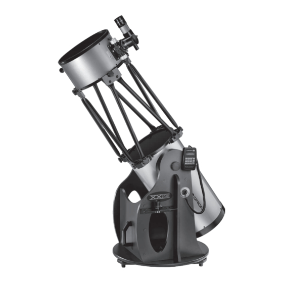
- Page 2 Finder scope Eyepiece Navigation Focuser knob Upper optical tube section Altitude tensioning (CorrecTension) knob Truss pole assembly (4x) IntelliScope Object Locator Lower optical tube section Dobsonian base Base handle Eyepiece rack Figure 1. The SkyQuest XX12 IntelliScope Truss Tube Dobsonian.
-
Page 3: Table Of Contents
4. Using your Telescope ....19 telescope needs to be shipped to another location, or returned to Orion for warranty repair, having the proper packaging will 5. Astronomical Observing ... 22 help insure that your telescope will survive the journey intact. -
Page 4: Parts List
Parts list Box #2: Dobsonian Base (refer to Figure 4) Box #1: Optical Tube Assembly and Accessories Qty. Description (refer to Figure 2) Left panel Qty. Description Right panel Lower tube section Front brace Upper tube section Top baseplate Dust covers Ground baseplate Truss pole assemblies Side braces... - Page 5 Dust cover (2x) Truss pole assemblies (4x) Lower tube section Upper tube section IntelliScope Cooling accelerator Object Locator kit fan kit Finder scope bracket with O-ring 35mm Deep View eyepiece 9x50 Finder scope 10mm Sirius Collimation cap Plössl eyepiece Encoder disk Azimuth encoder board...
- Page 6 IntelliScope Object Locator Altitude encoder assembly Instruction manual Altitude encoder nylon spacer washers (2x) Encoder wood screws (3x) Azimuth encoder cable (shorter) Bumper Altitude encoder Wire clips (6x) cable (longer) Azimuth encoder Controller cable spacer washer, thin Nylon hook-and-loop 9V Battery adhesive strips Figure 3.
-
Page 7: Assembly
Azimuth encoder Encoder spacer washers, wood thick (2x) screw Pilot hole baseplate Azimuth encoder spacer washer, thin Azimuth encoder board Figure 6. To install the azimuth encoder board, insert an encoder board mounting screw through the slotted hole in the board. Then, add two thick and one thin encoder spacing washers onto the screw. - Page 8 Azimuth encoder board Top baseplate Ground baseplate Brass azimuth bushing Encoder disc Figure 7. Lower the top baseplate onto the bottom baseplate. The brass bushing should pass through the center hole in the top baseplate (and the large hole in the azimuth encoder board). 7.
- Page 9 Right panel Altitude encoder Altitude bearing assembly cylinder screw Altitude bearing cylinder Encoder Altitude encoder mounting screw spacer nylon washer Figure 9. Push a bearing cylinder through the side panel and thread it into the altitude bearing cylinder. The beveled end of the cylinder should be facing away from the side panel.
- Page 10 (the end of 22. Insert one end of the controller cable into the larger of the the handle with the Orion logo should be facing upwards). two jacks on the top of the IntelliScope Object Locator.
- Page 11 Left panel Eyepiece rack Eyepiece rack wood screws Figure 15. Using the two eyepiece rack wood screws, install the Figure 16. eyepiece rack into the pilot holes near the top of the oval cutout in To remove the rear end ring, unthread the six screws the left panel.
- Page 12 Shaft Spring Figure 17. Place the three springs on the exposed threaded shafts of the mirror cell. Figure 20. Locate the area of tube that is bulging out and preventing the end ring from fully seating. 2. Next, assemble the rear end ring to the mirror cell. Find a clean, flat surface, and turn the mirror cell over so that the mirror is facing downwards.
- Page 13 4mm hex key to tight- shown. Note the orientation of the nameplate label on the upper en the button head cap screws which connect the poles tube section relative to the Orion logo on the lower tube section.
- Page 14 Altitude Truss Button head cap screw side bearing connector Altitude tensioning Truss metal washer poles Figure 23. The position of the truss connectors relative to the Altitude tensioning pole ends can be adjusted to register the truss connectors with the Teflon washer upper truss support ring.
- Page 15 2" Adapter Tensioner Thumb screws Coarse focus Coarse knob focus knob Focus lock thumb screw Drawtube Black nylon tensioning Fine focus thumb screws set screw knob Figure 27. Figure 29. Pull-back on the tensioner and slide the finder scope The 2" DeepView eyepiece installed in the focuser. into its bracket until the O-ring is seated in the bracket ring.
-
Page 16: Aligning (Collimating)
drawtube Reflection of primary mirror clip Figure 31. Collimating the optics.(a) When the mirrors are properly aligned, the view down the focuser drawtube should look like this. (b) With the collimation cap in place, if the optics are out of alignment, the view might look something like this. (c) Here, the secondary mirror is centered under the focuser, but it needs to be adjusted (tilted) so that the entire primary mirror is visible. - Page 17 To center the secondary mirror under the focuser, hold the mirror holder in place with one hand while adjusting the center more sophisticated alignment devices, such as the Orion screw with a Phillips screwdriver. Do not touch the mirror’s surface! LaserMate Laser Collimator.
-
Page 18: Aligning The Primary Mirror
Figure 36. The tilt of the primary mirror is adjusted by turning one or more of the three collimation knobs. Figure 35. Adjust the tilt of the secondary mirror by loosening or tightening the three alignment set screws with a 2mm hex key. The secondary mirror should now be centered in the focuser drawtube. -
Page 19: Using Your Telescope
rectly collimated, the expanding disk should be a perfect circle (Figure 37). If the image is unsymmetrical, the telescope is out of collimation. The dark shadow cast by the secondary mirror Altitude should appear in the very center of the out-of-focus circle, like the hole in a doughnut. -
Page 20: Focusing The Telescope
Nylon alignment Finder scope bracket thumbscrews Finder scope Naked-eye view View through finder scope and telescope Focus Tensioner Figure 40. The view through a straight finder scope and reflector lock ring telescope is rotated 180°. This is true for the XX12 and its finder scope as well. - Page 21 ing the alignment thumb screws, you change the line of sight field of view. Notice that the object being viewed is now larger, of the finder scope. Continue making adjustments to the align- but somewhat dimmer. ment thumb screws until the image is centered in both the Magnification, or power, is determined by the focal length of finder scope and the telescope’s eyepiece.
-
Page 22: Astronomical Observing
bearings on the optical tube and increase the friction. With observing tips and briefly summarize what you can expect to CorrecTension, the added weight of front-end loads will not see. adversely affect the balance of the telescope. Simply tighten the intelliscope computerized object locator the tensioning knob to compensate for an extra load. - Page 23 (see below). Also, use of a light-pollution fil- you can see with your unaided eyes. If you cannot see stars ter, like the Orion SkyGlow Broadband filter, can mitigate the of magnitude 3.5 or dimmer, then transparency is poor.
-
Page 24: Cooling The Telescope
cooling the telescope to access a wide range of magnifications. This allows the observer to choose the best eyepiece to use depending on All optical instruments need time to reach thermal equilibrium the object being viewed. At least to begin with, the two sup- with the outdoor air, which is essential for peak performance. -
Page 25: Care And Maintenance
Saturn’s moons, which look like faint nearby stars. images of bright objects. Certain imaging accessories, such The brightest is the moon Titan. as the Orion SteadyPix, can help in obtaining images by the Venus: At its brightest, Venus is the most luminous object in afocal method. -
Page 26: Specifications
7. specifications then remove any excess fluid with a fresh lens tissue. Oily fin- gerprints and smudges may be removed using this method. Use caution; rubbing too hard may scratch the lens. For larger optical tube assembly lenses, clean only a small area at a time using a fresh lens tis- Primary mirror: 305mm diameter reflective surface, sue on each area. - Page 27 Base weight: 34 lbs. Approximate base dimensions: 25" diameter x 30.5" tall accessories 2" Eyepiece: 35mm Deep View, multi-coated, threaded for Orion filters 1.25" Eyepiece: 10mm Sirius Plössl, multi-coated, threaded for Orion filters Eyepiece magnifications: 43x and 150x Finder scope: 9x power, 50mm aperture, achromatic, crosshairs, 5°...
- Page 28 Orion’s option, any warranted instrument that proves to be defective, provided it is returned postage paid to: Orion Warranty Repair, 89 Hangar Way, Watsonville, CA 95076. If the product is not reg- istered, proof of purchase (such as a copy of the original invoice) is required.
Need help?
Do you have a question about the SkyQuest XX12 Intelliscope Truss Tube Dobsonian 9793 and is the answer not in the manual?
Questions and answers