Table of Contents
Advertisement
Advertisement
Table of Contents

Summary of Contents for Brigade Electronics MDR-304A
- Page 1 MDR-304A Digital Video Recorder Instruction Manual Stock code: 2919A...
-
Page 2: Safety Precautions
SAFETY PRECAUTIONS All the following safety and operation instructions which will prevent harm or damage to the operator or other persons should be read before the unit is operated. INFORMATION This equipment has been tested and found to comply with the limits for a Class A digital device, pursuant to Part 15 of the FCC Rules. -
Page 3: Table Of Contents
Manual Recording ........27 1. INTRODUCTION ........3 Playback Operations ........27 Product Features..........3 Normal Playback ......... 27 Accessories............4 Fast Forward/Backward ......27 Front View ............6 Slow Forward/Reverse........ 27 Rear View............8 Play back picture-by-picture......28 MCU Rear View ..........9 Search Operations ........28 Power Delay Connection ......10 FULL LIST Search........ -
Page 4: Introduction
Vibration and mechanical shock protection. By taking advantage of the optional G-Sensor, the MDR-304A will register and record X, Y & Z impact data in the event of an accident and can be used as an alarm trigger. -
Page 5: Accessories
Sub-System Sub-System Sub-System Sub-system Description Sub-system Description Sub-system Description MCU-304A-XXX (Mobile Caddy Unit) MCU-304A-XXX (Mobile Caddy Unit) MCU-304A-XXX (Mobile Caddy Unit) MDR-304A-DS (Docking Station) MDR-304A-DS (Docking Station) MDR-304A-DS (Docking Station) (2798A) (2798A) (2798A) AVM-304 (Anti-Shock/Vibration AVM-304 (Anti-Shock/Vibration AVM-304 (Anti-Shock/Vibration Mounting) - Page 6 USB-001 (USB Lead) (2918) MDR-304A-TRIG (Trigger Cable) (2997A) MDR-304-SK (2x Security Keys) (2994) MDR-304-STS (4x Self Tapping Screws) (2995) Notes: The MDR-304A should not be operated without the anti-shock/vibration mounting unit. Stock codes that are underlined are not available separately.
-
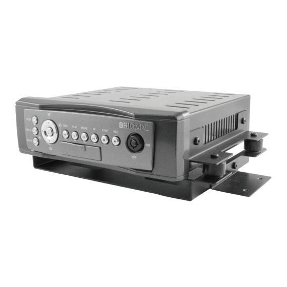
Page 7: Front View
Front View PLAY mode.) SETUP button: Press this to enter the setup menu. Press PAUSE button: again to exit the setup mode. In a playback display, press this to freeze the display. During the freeze, Left/ Right/ Up/ Down (CH1/ CH2/ CH4/ CH3) buttons: press to display one frame of a picture at In the menu setup mode / search mode,... - Page 8 glows red in the REC mode.) MCU Lock: This key lock secures the MCU with the hard disk in place. When you lock it in, it powers on the device. When you unlock this key and take out the inner case, the power turns off automatically.
-
Page 9: Rear View
Rear View Audio Out AUX1 Camera In Video Out AUX2 Remote RS-232 12V 9V 6V G-SENSOR IN1 IN2 IN3 IN4 +24V Power Delay 30A MAX OUT1 OUT2 +12V ACC GPS & Remote Controller Connector: The left side connector links up with the optional GPS receiver to capture local position information data. -
Page 10: Mcu Rear View
MCU Rear View Plug Inlet: The inlet connects to an external power supply. Connect to 12V DC UL Listed Class 2 Power Supply. Hard Metric Connector (Male): This connector links up with the outer casing. Audio Connector: Line level audio output for when the host is powered independent of the outer case. Video Connector: Composite video output for when the host is powered independent of the outer case. -
Page 11: Power Delay Connection
Enter the MDR-304A's "MAIN MENU" page and choose the third item, "CLOCK / TITLE". Now enter the "CLOCK / TITLE" page, and you will see two items, "DELAY ON" and "DELAY OFF". For both these items, the default setting is "OFF". -
Page 12: The Power Connector
The Power Connector Connect either pin 2 (24V) or pin 3 (12V) depending on vehicle voltage. Pin connections with the ignition key 12V: This method of connection is the most accepted and is recommended for permanent vehicle 24V: installations where either the post record duration or motion detection features will be used. - Page 13 Pin connections without the ignition key. 24V: This method of connectivity is recomended for temporary installations only. Post record or motion detection is not possible.
-
Page 14: I/O Port
I/O Port This figure is seen from the rear view. I/O IN1 (INPUT): This is an alarm input which can be programmed in the menu system to Normally Open or Normally Closed. I/O IN2 (INPUT): same as above. I/O IN3 (INPUT): same as above. I/O IN4 (INPUT): same as above. -
Page 15: I/O Connection
I/O Connection ALARM: In the "MAIN MENU" page, click "ALARM" to enter the "ALARM" page and then go to the "I/O CONNECTION" item which has three options, "ALARM", "VEHICLE SIGNAL T" and “VEHICLE SIGNAL A”. If you choose "ALARM" pins 1, 2 and 3 will become alarm input triggers which can receive a 12v-24v trigger voltage. Pin 4 is a "Reset"... -
Page 16: Voltage Management
Please consult the above diagram to know the battery voltage status. Note: The MDR-304A will not beep when the Buzzer function is disabled. Warning: If the supply voltage exceeds 36 volts the recorder will be damaged and the warranty may be... -
Page 17: Installation
(X, Y, Z, G ): The value “G” is only used when the Pressing the Display button once, will display MDR-304A connects with a G sensor, which can the figure 2.3A. Press the Display button again; detect the vehicle acceleration force or G force. -
Page 18: Channel Selection
1. Turn off the MDR-304A. 2. Insert the SD card into the built-in SD slot. 3. Turn on the MDR-304A. 4. The MDR-304A sounds a tone and displays the message “ XXXXXX BYTES READ”. Now the MDR-304A is updating the system software, which will take approximately 90 seconds to process. -
Page 19: Set Up
Recording time will vary depending on the image a recording configuration, please refer to the size, recording rate, and the capacity of the system information of the MDR-304A. (Please hard-disk drive (HDD). The table below shows the refer information for more details.) possible recording times per 80GB at different refresh rates and image quality. -
Page 20: Alarm Recording
MAIN PAGE Externally Triggered Recording By connecting the ALARM IN of ALARM I/O on the rear panel of the MDR-304A, you can activate / deactivate the alarm recording function of an MDR-304A. The file will be kept with a prefixed “A”. -
Page 21: Rec Setting
MAIN PAGE POST-REC DURATION: After the ACC is powered off (ACC OFF), the REC RATE: MDR-304A will continue recording for the time This option is for adjusting the number of pictures which is set in the "POST-REC DURATION" recorded very second. -
Page 22: Alarm
range from "00" (mute) to "10" (full). SPLIT: This option determines the layout of the screen. Alarm You can select from 4CH, 3CH, and 2CH. The Recording program settings for when an alarm resulting layout on the screen will be as follows. input is activated. - Page 23 The duration of recording will depend on the "ALM DURATION" setting. The length of D uration time the MDR-304A will remain in a state of Alar m Alar m “watch” will depend on the “Post Record”...
-
Page 24: Clock/ Title Settings
: O F F D E L AY O F F OPTIONAL RELAY Located on the rear of the MDR-304A, can be M A IN PA G E used to make an electrical connection to supplementary device when the MDR-304A is powered up. -
Page 25: Disk Settings
RS-232 CONNECTION: This function is disabled important image files in an SD card. JPEG: Archives images in the JPEG format, to and not supported on the current MDR-304A. save a single picture in every file. AVI: Archives images in the AVI format, to save a... - Page 26 OSD LANGUAGE (optional): Choose which language to use. SD SETUP: The MDR-304A offers a quick setup method by MENU BACKGND: using an SD card. To set up a number of There levels...
-
Page 27: Alarm And Motion Settings
5. If the "POST-REC DURATION" time ends while the manually or automatically according to the auto start “DELAY OFF” time is still active, the MDR-304A will record setting. To activate an alarm recording, set the not start a post-recording or a motion recording, and... -
Page 28: Operations
PLAY message and the PLAY button will playback. Each subsequent light up indicating that the MDR-304A is in the pressing of the FF button to the right playback status. increases the forward rate, as 2x, 4x, To switch between channels 1–4 and the quad 8x, 16x, 30x and 100x. -
Page 29: Play Back Picture-By-Picture
(3) Normal: Press the PLAY button to return to NOTE: The maximum number of index items in the normal speed of playback. the list in a hard disk drive is 3000. ALARM LIST Search Play back picture-by-picture 1) Press the SEARCH button to enter the While playing back recorded video at the recorded speed: search mode. -
Page 30: Thumbnail Search
(5) If no video is found, please return to the clicking the PLAY button. time-setting page and repeat steps (3) and (4) for another search. SEARCH THUMBNAIL FULL LIST ALARM LIST MM DD YEAR TIME SEARCH / 10 / 2004 SEARCH THUMBNAIL SD CARD... -
Page 31: Backup Operations
(5) Start playing back the recorded video. ●The AVI file format cannot be played and deleted in (6) Press the PAUSE button to freeze the the MDR-304A. It can only be played in a card desired pictures. reader connected to a computer. -
Page 32: Key Lock Operation
Set SD SETUP to SAVE. Then the system setting information will be automatically saved in the SD card. Transfer the system setting info of the MDR-304A to another MDR-304A: Insert the SD card which has stored the system setting... -
Page 33: Miscellaneous
5. MISCELLANEOUS System Default MAIN MENU RECORD ALARM CLOCK/ TITLE COMMUNICATION DISK SYSTEM GOTO REC PAGE COMM SETTING REC SETTING COMM ID : 0.1 AUTO START REC : OFF RS232 ENABLE : ON : 20 F/S REC RATE RS232 CONNECTION : GPS REC QUALITY : BEST... -
Page 34: O.s.d Messages
O.S.D Messages No. O.S.D Message Meanings NO DISK No hard disk detected after power activated BATTERY LOW Check vehicle battery BATTERY HIGH Check vehicle alternator output LOADING System Boot up VIDEO LOSS Video loss VIDEO IN Video input source KEY LOCKED Key lock function is on KEY UNLOCKED Key lock function is off... -
Page 35: Time Index Table
Time Index Table The MDR-304A will generate a Time Index Table for recorded data stored in a particular HDD. This allows recorded data to be found and displayed via the alarm list search and full list search. The maximum number of lists for a given HDD is 3000. When the list of any given HDD is used up and the disk is not full, the unit will still use the rest of the space for recording. -
Page 36: Specifications
Specifications Video system NTSC / PAL Video Video input Video output Audio input 6 CH (Rec 1 Ch) Audio Audio output 1 CH Compression MPEG4 Resolution & Frame rate 120 / 100 IPS @ CIF (NTSC/PAL) Recording mode Auto / Manual / Alarm trigger Recording Watermark Digital signature... -
Page 37: Hdd Viewer
HDD Viewer Introduction HDD Viewer makes it possible to search recorded video for critical moments and export and convert images into standard AVI video file or single image JPEG files. The Hi-Speed USB 2.0 interface (compatible with USB1.1) allows for fast transfer of raw data onto larger storage devices for long term archiving of files should they be required at a much later date. -
Page 38: Installation Instructions - Software
Installation Instructions - Software Installing from the CD-ROM Insert the CD-ROM in your CD Drive and follow the on-screen instructions. If your Auto Play option is disabled in your CD-ROM drive, you will need to navigate to the CD-ROM drive through Windows Explore or My Computer and double click on the Setup.exe file. - Page 39 STEP 3: LICENSE AGREEMENT Click I Agree to continue after reading the license agreement. STEP 4: SET UP THE INSTALLATION FOLDER Browse to select the path for the software modules, or just go on to the next step if you select the default path of C:\Program Files\HDD Viewer.
- Page 40 STEP 5: FINISH THE INSTALLATION Click Finish to complete the installation. STEP 6: START TO USE THE HDD VIEWER After completing installation, you can double-click the icon in the desktop, which is shown below. Or click "Start Menu" in the computer and select "Programs" to open the "Program Selection" page. Then click the "HDD Viewer"...
-
Page 41: Installation Instructions - Hardware
Connecting the MDR-304A and PC by the USB2.0 Cable: Take the USB cable and insert it into the front panel of the MDR-304A, linking the other end to a PC. Then open the HDD Viewer. Use the USB cable to connect the USB... - Page 42 8. Select the mode & select the Rec. Type (Normal/ Manual/ Alarm): Disk Mode: In this mode, the software will list the files in the MDR-304A hard disk. File Mode: In this mode, the software will list the files in a specified directory (eg files downloaded from MDR-304A and stored on a PC).
- Page 43 9. Export (G-sensor X, Y & Z data in Excel format): (1) Select a recorded file from the file list. Then press the Export button. (2) Specify the file path to be used when exporting the picture and other information in the Information dialog.
-
Page 44: Advanced Operation
Advanced Operation Save a snapshot to a PC Step 1. Click the button to save a single picture in the JPEG format. Step 2. Please specify the File Name/ File Path to which you want to export the picture. Step 3. After specifying the name and the path, please click the "Save" button to start the export. You can also click "Cancel"... -
Page 45: Read The Csv Report
Read the CSV report The CSV report helps you to analyze the vehicle status and messages from the G-sensor. The G-sensor is a 3-axis (X/ Y/ Z) accelerometer which is able to detect the magnitude and direction of acceleration. The G-sensor can be used to sense orientation (because the direction of velocity changes), coordinate acceleration (so long as it produces g-force or a change in g-force) and provides the measurement of low g forces resulting from fall, tilt, motion, positioning, shock or vibration. - Page 46 3. Lat/ Lon: This stands for the latitude and longitude that the GPS receives. 4. GPS speed: The velocity which is measured by the GPS receiver. 5. Alarm: Stop: The car stops at a signal light. Left/ Right: The left-side car signal light/ the right-side car signal light.
-
Page 47: Appendix 1. -Table Of Log Message
APPENDIX 1. –Table of LOG Message MENU SETUP LOG -- REC SETTING PAGE -- 1>.AUTO START REC --> M-R ASR OFF AUTO START REC 0 SEC --> M-R ASR 0 SEC AUTO START REC 1 MIN --> M-R ASR 1 MIN 2>.DISK FULL REWRITE -->... - Page 48 -- DISK SETTING PAGE -- 1>.HD REFORMAT --> M-D HD REFORMAT M-D A-ERASE OFF 2>.AUTO ERASE --> AUTO ERASE --> M-D A-ERASE SET 3>.SD REFORMAT START --> M-D SD REFORMAT M-D G-STAMP ON 4>.GPS STAMP --> M-D G-STAMP OFF GPS STAMP -->...
- Page 49 The G-sensor The value “G” is only used when the MVR connects with a G sensor, which can detect the vehicle acceleration force or G force. The G value is equal to the square root of the x²+y²+z². The user can set the G-sensor sensitivity which is a limited value for corresponding with the value “G”...
- Page 50 Brigade Electronics Plc Brigade House, The Mills, Station Road, South Darenth, Kent DA4 9BD Sales +44(0) 1322 420300 Facsimile +44(0) 1322 420343 www.brigade-electronics.com sales@brigade-electronics.com Stock code: 2919A 1774 Dec 11...
Need help?
Do you have a question about the MDR-304A and is the answer not in the manual?
Questions and answers