
Subscribe to Our Youtube Channel
Related Manuals for Viola Systems H.264

Summary of Contents for Viola Systems H.264
- Page 1 User’s Manual Before attempting to connect or operate this product, please read these instructions carefully and save this manual for future use. - 1 -...
- Page 2 CAUTION TO REDUCE THE RISK OF ELECTRIC SHOCK, DO NOT REMOVE COVER. NO USER SERVICEABLE PARTS INSIDE. PLEASE REFER SERVICING TO QUALIFIED SERVICE PERSONNEL. WARNING TO PREVENT FIRE OR ELECTRIC SHOCK HAZARD, DO NOT EXPOSE THIS APPLIANCE TO RAIN OR MOISTURE. NOTE: This equipment has been tested and found to comply with the limits for a Class “A”...
- Page 3 LIMITATION OF LIABILITY THIS PUBLICATION IS PROVIDED “AS IS” WITHOUT WARRANTY OF ANY KIND, EITHER EXPRESS OR IMPLIED, INCLUDING BUT NOT LIMITED TO, THE IMPLIED WARRANTIES OF MERCHANTIBILITY, FITNESS FOR ANY PARTICULAR PURPOSE, OR NON-INFRINGEMENT OF THE THIRD PARTY’S RIGHT. THIS PUBLICATION COULD INCLUDE TECHNICAL INACCUACIES OR TYPOGRAPHICAL ERRORS.
- Page 4 PRECAUTIONS Please refer all work related to the installation of this product to qualified service personnel or system installers. Do not operate the appliance beyond its specified temperature, humidity or power source ratings. Use the appliance at temperature within 0 C ~ +45 C (32 F ~ 113...
-
Page 5: Table Of Contents
Table of Contents 1. Product Overview………………….……………………….……... Features…………………..…….…………..…………………... 2. Panels And Remote Controller…………...………………….……. 2.1 Front Panel………….……….…………………………….……. 2.2 Back Panel………………….…………………………….…….. 2.3 Remote Controller…………..…….……………………….…… Installations…….…….……………………………………….…… 3.1 Basic Connections…………….………………………….…….. 3.2 Optional Connections…………..………………………….…… 4. Main Screen And Basic Operations………….……..……….…... 4.1 Text Input……………………………………….……………… 4.2 Login And Logout………………………………………………... - Page 6 6.10.1 E-mail Setup……………..……………………………….. 6.10.2 FTP Setup……………..………………………………….. 6.10.3 Advanced Network Setup……………..………………… 7. PTZ Control……………………….……………………………… 8. Search/Playback/Archive (Administrator/Supervisor) ………..8.1 Search By Time……………………………………….………… 8.2 Search By Event / Log Display………………………….……… 8.3 Smart Search………………………..………….……….……… 8.4 Search Archived Files………………………….……….……… 8.5 POS Search…………………………………….……….……… 8.6 Playback/Archive For Search By Time………….….….………...
-
Page 7: Features
1. Product Overview The H.264 digital video/audio recorders are designed for use within a surveillance system and are a combination of a hard disk recorder, a video multiplexer, and a web server. To achieve the highest inter-connectivity and inter-operability, this series of digital video/audio recorders are all based on industry-leading front-end to back-end surveillance infrastructure. - Page 8 Multi-lingual support Multi-level password and authentication key protection to ensure high degree of security Streaming video for mobile phone or PDA, no Apps required N-Streaming internet/intranet remote access GPS support POS support Support mouse operation - 8 -...
-
Page 9: Panels And Remote Controller
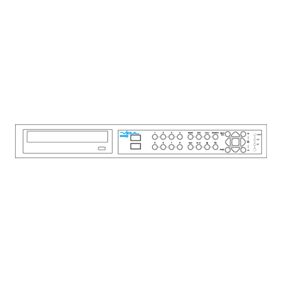
2. Panels and Remote Controller 2.1 Front Panel 1. Alpha-numeric Buttons (1-4/8) Press these buttons for camera selection in most of the circumstances. These buttons can also be used to enter text and number in the way similar to most of the mobile phones. 2. - Page 10 6. REC Button Press this button to force manual recording. To stop manual recording, press it again. 7. Play/Pause Button ( Press this button to play the recorded images, or pause the playback. 8. Stop ( ) Button Press this button to stop the playback. 9.
- Page 11 display. In the others, press these buttons to change the contents. 17. LEDs Indicators for POWER, HDD and Network access. 18. Remote I/R Sensor Used to receive signal from I/R remote controller. 19. USB2.0 Connector Connect to USB 2.0 compatible storage device, such as USB 2.0 disk drive, DVD+RW, card reader, etc.
- Page 12 2.2 Back Panel 1. Video Input Connectors (1-4/8) Connect system cameras to these BNC connectors. The internal 75Ω termination is always ON. 2. Main Monitor Output Connectors (MAIN OUT) Connect TV monitors to the BNC connector for main monitor display. 3.
- Page 13 8. Alarm Input Connectors (ALARM IN 1-4) Connect these connectors to external devices such as sensors or door switches. 9. Alarm Output Connectors (ALARM OUT NC(1)/NO(2)) Connect NC connectors (left) to Normally Closed (NC) alarm output, or NO connectors (right) to Normally Open (NO) alarm output. Please note that only one of the NC or NO connectors can be connected only.
-
Page 14: Remote Controller
2.3 Remote Controller The remote controller is an optional accessory to ease the user’s operations. You can do all the operations by the remote controller instead of the buttons on the front panel. The effective distance is about 10 meters without any obstacle. Most of the buttons corresponds to one of those buttons on the front panel. -
Page 15: Installations
3. Installations The installations described below should be made by qualified service personnel or system installers. 3.1 Basic Connections Please refer to the following diagram for the connections. Please make sure to set the NTSC/PAL Selector Switch on the main board according to the local TV system for the system to work correctly. -
Page 16: Optional
Connect DC 12V power source to DC 12V Input. 3.2 Optional Connections Audio input Connect the audio input connector to the audio line-out from system cameras or other audio sources. Please make sure to associate the audio inputs with the cameras in Camera Setup as described in Section 6.2 accordingly. - Page 17 I/R remote controller The user may use I/R remote controller to control the digital video/audio recorder. PTZ Cameras Connect the RS-485 connector to PTZ camera(s) via the appropriate cable. The system supports a variety of different PTZ cameras, including Pelco D protocol Dome, SamSung SCC-641P, Kalatel Cyber Dome, Bosch AutoDome, etc.
- Page 18 POS system Connect the RS-485 connector to POS system via the appropriate cable. The system supports the POS systems which can be connected to the following printers – Epson-TM200, Epson-TMU295, Epson-TMU300, Epson-TMU675, Epson-TMT882, Epson-RPU420, and Epson-MD332S. Please make sure to setup the RS-485 port (Section 6.9) accordingly.
-
Page 19: Main Screen And Basic Operations
4. Main Screen And Basic Operations The split-window screen, as shown above, is the main screen after system startup. There are several types of split-window screens, including 1-Window, 4-Window, 7-Window, and 9-Window. The system will remember the last one before normal shutdown (as described in Section 5.7) of the system. -
Page 20: Text
4.1 Text Input There are certain circumstances that the system requires the user to enter text, such as system login, camera title setup, and so on. Please follow the steps below to enter text: (1) Press ENTER to edit the highlighted option. The flashing cursor will be shown to indicate the editing point. -
Page 21: Login And
4.2 Login And Logout There are three password levels in the system, including Administrator (highest), Supervisor, and Operator (lowest). If the user does not login the system, he/she will be treated as “Guest” and can only view live video display. The system allows up to 18 user accounts. -
Page 22: Menu
the buzzer. MODE (Mouse: (Administrator/Supervisor) In split-window display, press this button to change circularly the live/playback mode for the focus window and the other windows that form a rectangle on the screen. (Mouse: Press this button to switch to or return from SEQ display mode. In SEQ display mode, each page in the sequence will be shown for the preset page dwelling time sequentially, and SEQ icon will be shown on the lower-right corner of the screen. -
Page 23: Digital Zoom
(Mouse: Press these buttons to circulate up/down among the available split-window displays. PAGE (I/R remote controller: #, Mouse: current split-window icon) Press this button for page down in multi-split-window displays. ENTER (Mouse: Press this button to display the GPS/POS data if there’s GPS/POS data fed to the DVR. - Page 24 mode are as below: (Mouse: Click in the video window) ▲▼◄► Press these buttons to (a) move the zoom window if it’s shown in the video window, or (b) navigate the video window around if the zoom factor is X2 or X4. ENTER (Mouse: Click in the video window) Press this button to zoom in the zoom window, from X1 to X2 or from X2 to X4,...
-
Page 25: Menu Display
5. Menu Display In split-window display, press MENU (Mouse: to call up Menu display as shown. There are a variety of displays under Menu display. In Menu display and all the subsequent displays, the items enabled are shown in black-colored text, and those disabled in white-colored text. -
Page 26: Status Display
5.1 Status Display In Menu display, press ▲▼◄► to change the highlighted option to Status, and then press ENTER to call up Status display as shown. Status display includes Alarm Recording Status, Normal Recording Status, Camera Status, Alarm Input Status, Product Serial Number, and Product Version Number. Press ESC (Mouse: Right Click) to escape from Status display, and return to Menu... -
Page 27: Volume Control
5.2 Volume Control Menu display, press ▲▼◄► change highlighted option to Volume, and then press ENTER to call up Volume Control display as shown. The general operations are as below: ▲▼◄► (Mouse: Click in the respective item) Press these buttons to select the items. (Mouse: Right Click) Press this button to escape from this screen, and return to Menu display. - Page 28 There are 4 items which can be adjusted, including Brightness, Contrast, Hue, and Saturation. The operations are as below: ▲▼ Press these buttons to select the items. Numeric (Mouse: Press these buttons to change the camera. Press these buttons to adjust the selected item. (Mouse: Press this button to reset the settings for this camera to factory default values.
-
Page 29: Vga Display
5.4 VGA Display In Menu display, press ▲▼◄► to change the highlighted option to VGA Display, and then press ENTER to call up VGA Display dialog as shown. There are 5 items which can be adjusted, including Resolution (only 1024x768 for this model), Brightness, Contrast, Hue, and Saturation. -
Page 30: Backup
5.5 Backup Device In Menu display, press ▲▼◄► to change the highlighted option to Backup Device, and then press ENTER to call up Backup Device display as shown below. The system supports internal DVD for Internal DVD models and a variety of USB 2.0 storage devices, including Storage Disk such as USB 2.0 storage disk drives and DVD Disc (including DVD+RW, DVD+R, and DVD-R). - Page 31 Note 2: Before using USB pen drive, please format it to FAT32 file system by MS-Windows. Note 3: The backup device has to be connected by the system software before it can be used to read/write. If it failed to connect, please unplug the device, and then plug the device in the USB port again.
- Page 32 NEC DVD/CD Rewritable Drive Model ND-4550A Series HP dvd9404e External 18X Super Multi DVD Writer Series Some DVD Discs Tested – Only single-side, single-layer disc is supported Infomedia DVD+R 16X Mitsubishi DVD+RW 1-4X Philips DVD+RW 1-4X Ritek DVD-R 8X Ritek DVD+RW 1-4X Verbatim DVD+RW 1-4X - 32 -...
-
Page 33: Software Upgrade (Administrator)
5.6 Software Upgrade (Administrator) In Menu display, press ▲▼◄► to change the highlighted option to Software Upgrade, and then press ENTER to call up Software Upgrade display as shown. The operations are as below: (Mouse: Left click) ▲▼◄► Press these buttons to select the items. (Mouse: Right Click) Press this button to escape from this screen, and return to Menu display. -
Page 34: System Shutdown (Administrator)
5.7 System Shutdown (Administrator) In Menu display, press ▲▼◄► to change the highlighted option to Shutdown, and then press ENTER (Mouse: Left click) to shutdown the system. A confirmation dialog will be shown on the screen, press ENTER to confirm the shutdown. The system will save all the files and all the states, and then display a power-off message in the rolling screen message area. -
Page 35: Setup
6. Setup (Administrator) In Menu display, press ▲▼◄► to change the highlighted option to Setup, and then press ENTER to call up Setup Menu display as shown. (To enter Setup Menu display of the system, please login as Administrator first.) The user’s operations are described as the followings: ▲▼◄►... -
Page 36: Pre-Camera
6.1 Pre-Camera Setup In Setup Menu display, press ▲▼◄► to change the highlighted option to Pre-Camera, and then press ENTER (Mouse: Left click) to call up Pre-Camera Setup display. There are up to 8/4 cameras which can be connected to the system. The Pre-Camera Setup allows the administrator to define some fundamental attributes, which may relate one camera to the others, for all the installed cameras. -
Page 37: Camera
360x288. Press +/- buttons to select the resolution. Watermark – to record with digital watermark or not. If yes, all the recorded images for all the cameras will have digital watermark embedded. Press ENTER or +/- (Mouse: Left click) to check/uncheck this item. The default setting is “ˇ”... -
Page 38: Alarm
▲▼◄► (Mouse: Left click) Press these buttons to select the items. The display will scroll left/right if the selected item is not shown on the screen. Numeric Press these buttons to select the camera. COPY ( Press this button to copy all the settings - excluding detailed Motion settings, Video Loss settings, Title/Audio - of the focus camera to all the following cameras. - Page 39 Dwell Time – the dwell time if Call By Event is set to Motion, Alarm, or Both. Press +/- buttons to adjust the value (3-60 seconds, discrete). Audio – the AUDIO IN corresponding to this camera. The audio data for the selected AUDIO IN will be recorded with the video data for this camera.
-
Page 40: Video Loss Setup
6.2.1 Video Loss Setup Camera Setup, press ENTER to call up Video Loss Setup of the selected camera as shown when the highlighted option is Video Loss Settings.. of the camera to setup. The Video Loss Setup allows the administrator to define how the system responds to the detected video loss for the camera. -
Page 41: Motion Setup
about preset locations, please refer to Chapter 7 PTZ Control. Pre-record – to define how long before video loss is detected this camera shall be intensively recorded at Pre-record IPS. Press +/- buttons to adjust the value (0-10 seconds, discrete). Please note that the actual pre-record time may be shorter than the value set if the total size of the pre-record pictures exceeds the pre-record buffer size of the system. - Page 42 The general operations are as below: (Mouse: Left click) ▲▼ Press these buttons to select the items. Numeric Press these buttons to select the camera. COPY ( Press this button to copy the Motion settings, including Detection settings, of the focus camera to all the following cameras.
- Page 43 Goto Preset – to define the preset position to go to for the “Camera to go” Camera in last field if motion is detected for this camera. For more details about preset locations, please refer to Chapter 7 PTZ Control. Pre-record –...
- Page 44 Mask window. Following is a brief description for the operations: Numeric (Mouse: Press these buttons to select the camera. ▲▼◄► Press these buttons to move the Mask window. (Mouse: Left click and drag) Press these buttons to resize the Mask window. ENTER (Mouse: Press this button to set/reset the area under the Mask window.
-
Page 45: Alarm Setup
Press this button to increase/decrease the “number of grids treated as motion” for the motion detection of this camera. SEARCH (Mouse: Press this button to test the motion detection of this camera. The detected motion will be shown on the screen. Press this button again to stop testing. (Mouse: or Right Click) Press this button to escape from Motion Detection Setup, and return to Motion... - Page 46 Numeric Press these buttons to select the alarm input. COPY ( Press this button to copy the settings of the focus alarm input to all the following alarm inputs. (EX. focus alarm input is 5, its settings will be copied to those of alarm inputs 6-16.) (Mouse: Right Click) Press this button to escape from this screen, and return to Setup Menu display.
- Page 47 Buzzer – to activate the internal Buzzer or not when this alarm input is triggered. Press ENTER or +/- to check/uncheck this item. The default setting is “ˇ” - checked. Log – to log to event logs or not. Press ENTER or +/- to check/uncheck this item.
-
Page 48: Seq Display
6.4 SEQ Display Setup In Setup Menu display, press ▲▼◄► to change the highlighted option to SEQ Display, and then press ENTER to call up SEQ Display Setup as shown. The SEQ Display Setup allows the administrator to define the display pages in SEQ Display for main monitor. - Page 49 In Display Page Setup, the split window display for the current page is shown. And the title of the camera for the focus window . Following is a is highlighted brief description for the operations: ▲▼◄► (Mouse: Left click) Press these buttons to move the focus window. Numeric (ENTER) (Mouse: Press these buttons to change the camera for the focus window.
-
Page 50: Scheduled Record Setup
6.5 Scheduled Record Setup In Setup Menu display, press ▲▼◄► to change the highlighted option to Scheduled Record, and then press ENTER to call up Scheduled Record Setup. The Scheduled Record Setup allows the administrator to define when and how to record for the system. - Page 51 Start – the start time of this time segment, increment at 30 minutes. (The end time of this time segment is implicitly set as the start time of next time segment, or the start time of the first time segment of the same weekday if it’s the last one.) Press +/- buttons to select the desired start time.
- Page 52 Motion, Normal, and No Record. Video & Audio are all recorded for the selectable Recording Modes except “No Record”. After the Easy Setup, the time segments for each weekday in Scheduled Record will be updated accordingly. The operations are as below: ▲▼◄►...
- Page 53 6.6 HDD Setup In Setup Menu display, press ▲▼◄► to change the highlighted option to HDD, and then press ENTER to call up HDD Setup as shown. In the surveillance applications, alarm video/audio is much more important than normal video/audio. So, this digital video/audio recorder is designed to allow the user to divide each HDD into alarm partition and normal partition.
- Page 54 Click) to exit without saving. Following is a brief description for each item and its specific operations: Size (GB) – the total HDD storage in GB (Giga-Byte) for Alarm Record and Normal Record respectively. This item is just for information. Please refer to Section 6.6.1 for more detailed information and setup of each individual HDD.
-
Page 55: Hdd Format/Clear
6.6.1 HDD Format/Clear In HDD Setup display, press MODE to call up HDD Format/Clear screen as shown. Each of the HDDs must be formatted before it can be used to record video/audio. The HDD Format/Clear screen allows the administrator to format and/or clear each HDD, and set the size for Alarm Record partition and Normal Record partition for each HDD. - Page 56 Note: If the HDD has not been formatted, it will be formatted and partitioned with default record size, 100% for Alarm record and 0% for Normal record. If it has been formatted (and recorded), it will be partitioned according to the Alarm Record Size (%) and Normal Record Size (%) displayed on the screen, and the previously recorded contents will all be cleared.
-
Page 57: Advanced Hdd Setup
6.6.2 Advanced HDD Setup In HDD Setup display, press SEQ to call up Advanced HDD Setup display as shown. The HDD Failure Action in Advanced HDD Setup allows the administrator to define how the system responds to the detected HDD failure, while the Privacy settings allow the administrator to set the DVR to record for Limited Period and the Retention Period of its HDD storage. - Page 58 Buzzer – to activate the internal Buzzer or not when HDD failure is detected. Press ENTER or +/- (Mouse: Left click) to check/uncheck this item. The default setting is “ˇ” - checked. Log – to log to event logs or not. Press ENTER or +/- to check/uncheck this item.
-
Page 59: Password Setup
6.7 Password Setup In Setup Menu display, press ▲▼◄► to change the highlighted option to Password, and then press ENTER to call up Password Setup as shown. The Password Setup allows the administrator to add new users, delete existing ones, and/or modify the user’s name, password, and/or level. - Page 60 (Mouse: Right Click) Press this button to escape from this screen, and return to Setup Menu display. If the Save dialog is shown, press ENTER to exit and save, ESC (Mouse: Right Click) to exit without saving. Following is a brief description for each item and its specific operations: Guest Level –...
- Page 61 Press these buttons to move the focus. If the selected item is not shown on the screen, the screen will scroll up or down. (Mouse: Right Click) Press this button to escape from this screen, and return to Password Setup display.
-
Page 62: Network
Setup Alarm – to enable the user to do Alarm Setup if “checked”. Press ENTER or +/- (Mouse: Left click) to check/uncheck this item. Setup SEQ Display – to enable the user to do SEQ Display Setup if “checked”. Press ENTER or +/- (Mouse: Left click) to check/uncheck this item. -
Page 63: System Setup
6.8 System Setup In Setup Menu display, press ▲▼◄► to change the highlighted option to System, and then press ENTER to call up System Setup as shown. The System Setup allows the administrator to set the system time, time zone, time synchronization, language, etc. - Page 64 System Time – Synchronization – time synchronized with TSP Server or not. Press ENTER or +/- to check/uncheck this item. The default setting is “–” - unchecked. TSP Server – TSP (Time Synchronization Protocol) server name if Time Synchronization is enabled. The system will try to do time synchronization with the specified TSP server at the system preset interval.
- Page 65 6.9 RS-232/422/485 Setup In Setup Menu display, press ▲▼◄► to change the highlighted option to RS-232/422/485, and then press ENTER to call up RS-232/422/485 Setup as shown. The RS-232/422/485 Setup allows the administrator to setup RS-485 control port. Please refer to the manuals for the connected devices - PTZ cameras or keyboard controllers –...
- Page 66 Epson-TM200, Epson-TMU300, Epson-TMU675, Epson-TMT882, Epson-RPU420, and Epson-MD332S) and Epson-TMU295. Press +/- buttons to change the supported model (or protocol). Please note that if PTZ+Keyboard is selected for Device Type, the Keyboard model is always Control Protocol, and the other settings (Baud Rate, Data Bit, Stop Bit, and Parity) are the same as the PTZ Model selected.
-
Page 67: Network Setup
6.10 Network Setup In Setup Menu display, press ▲▼◄► to change the highlighted option to Network, and then press ENTER to call up Network Setup as shown. The Network Setup allows the administrator to setup all Ethernet network related parameters. Please check with your network administrator to set these parameters correctly. -
Page 68: E-Mail Setup
Net Mask – Net Mask for the IP address. Please follow the Text Input method described in Section 4.1 to modify these items. Gateway – Gateway IP address for the system. Please follow the Text Input method described in Section 4.1 to modify these items. - Page 69 6.10.1 E-mail Setup In Network Setup, press ENTER to call up E-mail Setup as shown when the highlighted option is E-mail. The E-mail Setup allows the administrator to set e-mail related parameters. When an event occurs and E-mail is enabled for the corresponding action, an e-mail will be sent based on the parameters set here.
-
Page 70: Ftp
Username – username if the SMTP mail server requires authentication. Please follow the Text Input method described in Section 4.1 to modify this item. Password – password if the SMTP mail server requires authentication. Please follow the Text Input method described in Section 4.1 to modify this item. -
Page 71: Advanced Network Setup
Right Click) to exit without saving. Following is a brief description for each item and its specific operations: FTP Server – FTP server web/IP address. Please follow the Text Input method described in Section 4.1 to modify this item. FTP Port – the FTP port. The default value is 21. Please follow the Text Input method described in Section 4.1 to modify this item. - Page 72 The general operations are as below: ▲▼(Mouse: Left click) Press these buttons to select the items. (Mouse: Right Click) Press this button to escape from this screen, and return to Network Setup display. If the Save dialog is shown, press ENTER to exit and save, ESC (Mouse: Right Click) to exit without saving.
- Page 73 follow the Text Input method described in Section 4.1 to modify these items. Note: If the Control Port or Data Port is not available or accessible during remote access, the system will reset the ports to their default values, i.e. 67/68.
-
Page 74: Ptz Control
7. PTZ Control The digital video/audio recorder supports a variety of PTZ cameras. The user can easily control the PTZ cameras through the operations described in this Chapter if those PTZ cameras have been connected and setup correctly. Please refer to Section 3.2 Optional Connections for the connections. - Page 75 Miscellaneous function specific operations: Active function Operations Descriptions Focus (Mouse: focus far/near ENTER (Mouse: auto focus Iris Iris increase/decrease (Mouse: Auto Pan (3) Auto pan speed is shown in parenthesis increase/decrease speed (Mouse: ENTER start/stop Auto Pan set start position set end position SEQ (5 sec.) SEQ dwell time is shown in parenthesis.
-
Page 76: Search/Playback/Archive (Administrator/Supervisor)
8. Search/Playback/Archive (Administrator, Supervisor) There are five ways to search the recorded video/audio for playback: (a) Search by time, (b) Search by event, Smart search, (d) Search archived files, and (e) POS search. In split-window display, press SEARCH button (Mouse: to call up Search Menu display as shown. -
Page 77: Search By Time
8.1 Search By Time The screen for Search By Time is shown on the right side: The Status field will show the ‘Recorded from’ time based on the selected Video/Audio before searching - alarm partition if any of Alarm, Motion, or Video Loss, is checked, and normal partition if Normal is checked. - Page 78 recorded video/audio you want to search for playback. Press ENTER or +/- to check/uncheck each item. 8.2 Search By Event / Log Display The screen for Search By Event - Log display, is shown below: There are four different types of event logs, including Alarm, Motion, Video Loss, and System.
- Page 79 Please select the backup device, and enter the directory name you want, and then press COPY to copy the event log to the selected backup device. SEQ => Page Up (Mouse: Left click) CALL => Page Down (Mouse: Left click) Press SEQ/CALL to Page Up/Down the Log display.
-
Page 80: Smart
8.3 Smart Search The screen for Smart Search is shown below: The Status field will show the ‘Recorded from’ time in the HDDs before searching or the search result after searching. The general operations are as below: ▲▼◄► (Mouse: Left click) Press these buttons to select the items. - Page 81 Numeric (ENTER) (Mouse: Left click in the page number shown) Press these buttons to select the display page of the matched files in the list. Following is a brief description for each item and its specific operations: Camera ID – the camera to be searched for matched files. Its title is shown on its right side.
- Page 82 Following is a brief description for the operations: ▲▼◄► Press these buttons to move the Mask window. (Mouse: Left click and drag) Press these buttons to resize the Mask window. ENTER (Mouse: Press this button to set/reset the area under the Mask window. MODE (Mouse: Press this button to set/reset the whole video area.
-
Page 83: Search Archived Files
8.4 Search Archived Files The screen for Search Archived Files is shown below: The operations are as below: ▲▼◄► (Mouse: Left click) Press these buttons to select the items. (Mouse: Right Click) Press this button to escape from this screen, and return to split-window display. Following is a brief description for each item and its specific operations: Backup Device –... -
Page 84: Pos Search
8.5 POS Search The screen for POS Search is shown below: The Status field will show the ‘Recorded from’ time in the HDDs before searching or the search result after searching. The general operations are as below: (Mouse: Left click) ▲▼◄►... - Page 85 Numeric (ENTER) (Mouse: Left click in the page number shown) Press these buttons to select the display page of the matched files in the list. Following is a brief description for each item and its specific operations: Camera ID – the camera to be searched for matched files. Press +/- buttons to change the camera ID.
- Page 86 8.6 Playback/Archive For Search By Time In split-window display, press MODE button (Mouse: to change circularly the live/playback mode for the focus window and the other windows that form a rectangle on the screen. The video windows for the windows in playback mode are grayed, while those in live mode display live video.
- Page 87 Copy ( (Mouse: Press this button to copy or stop copying the playback video/audio to the storage device connected to the USB port or internal DVD. The Backup display will be shown as below. Following is a brief description for the operations in Backup display: (Mouse: Left click) ▲▼◄►...
- Page 88 Backup Device – the backup device connected to the system. Press ENTER (Mouse: Left click) on the left button to call up Backup Device dialog if there’s no backup device connected. Press +/- buttons on the right selection to select the connected device. Please follow the steps described in Section 5.5 Backup Device to connect the backup device before copying.
- Page 89 Playback Buttons ( These playback buttons are still operational as described above. ESC (Mouse: Right Click) Press this button to not show the playback slider bar. Except the playback buttons, the user can still do all the other operations in split-window display as if there is no playback.
-
Page 90: Playback/Archive For Smart Search
8.7 Playback/Archive For Search By Event In Log display, press Play Buttons ( (Mouse: Left click) to playback selected logs. This display is the same as full screen display of the main display, and the playback buttons are effective. The operations are as below: Playback Buttons ( , ENTER, MODE, SEQ, SEARCH) -
Page 91: Playback/Archive For Search By
8.9 Playback For Archived Files In Search Archived Files display, press ENTER to enter Archived File Playback display of the selected file, or press Play Buttons ( (Mouse: Left click twice) to playback it directly. This display is the same as full screen display of the main display, and the playback buttons are effective. -
Page 92: Remote Access
9. Remote Access 9.1 PC Remote Access The digital video/audio recorder can be accessed by using a web browser installed on a PC if this unit is connected to a network, either internet or intranet. Before Logging On Before accessing this unit through web browser, please make sure the followings (For most PCs, only step 4 &... - Page 93 9. Please go to Start->Setup->Control, select Display->Settings, and set the Screen Resolution to at least 1024x768 and Color to 32-bit. Firefox To use Firefox to access the DVR, please do the followings: 1. Launch Firefox. 2. Visit the web site "http://ietab.mozdev.org" to download and install IE Tab Plugin. 1.
- Page 94 Remote Display and Operations After the plug-in software is downloaded and run in the web browser, you will be asked (1) to install redistributable software, and (2) for ActiveX control to interact with your PC. Please select Yes, and the remote login display will be shown. Please note that the PC user must have system administrator password for the PC;...
- Page 95 In video window, right-click the mouse button to call up Camera/Playback/Print Dialog. (Left) click on Playback or Camera number to change the window to the corresponding camera and live/playback mode. The user may click on the “Print” button to print the video to the printer, or “Snapshot” the video. The user may double click for 1-Window display.
- Page 96 Click on this icon to show/hide the POS data (for 9-split-window or larger video window) for (1) the selected DVR, or (2) the DVR for the focus camera, button down to show, button up to hide. Click on this icon to backup video/audio, and the Backup dialog will be shown. Please select the DVR, cameras, event type, destination directory, execution time, and data range, and then click on “Apply”...
- Page 97 Playback panel for playback buttons, including Fast Backward, Fast Forward, Single Step, Play, Pause, Stop, and Copy (from left to right). Please note that the Copy function can be used to archive both live and playback streams. Please check/uncheck the cameras to be archived when the Copy Dialog is shown, and then click on OK or Apply button.
- Page 98 search of the recorded video/audio. (If it failed, the result will be shown on the title of the dialog.) Now, you may use the playback buttons to play the recorded video/audio. If there not any camera in playback mode, all cameras will be searched and played.
- Page 99 the same as the IP address (for Static IP) or URL (for PPPoE) in Network Setup for the (DVR) device. Control Port – the control port for the (DVR) device. The default value is 67. Data Port – the data port for the (DVR) device. The default value is 68. Video Stream –...
- Page 100 Click on this icon to call up GPS Configuration dialog. Please select the DVR device. Then select Display attributes and Output attributes for Live & Playback respectively. If Data Exchange File is enabled, the corresponding GPS data will be output to the file specified. Please note that Tag and Icon are to be used by GPS software such as Google Earth for display purpose.
- Page 101 MicroSoft ® DirectX ® 9.0 or above. Others Windows XP KB319740 Package if Windows XP SP2 is installed. - 101 -...
-
Page 102: Pda/Mobile Phone Remote
9.2 PDA/Mobile Phone Remote Access The digital video/audio recorder can also be remotely accessed by using a web browser installed on a PDA or mobile phone (EX. Nokia 5300, 6120C, Sony Ericsson W850i, Z610i) that (1) supports xHTML and MJPEG file format, and (2) has screen resolution at 240x320 or above. -
Page 103: Appendix A - Specifications
Output 1 RCA-jack connector, line-out level (up to 2Vrms) Record Compression Video: H.264 Audio: ADPCM Frame rate (IPS) NTSC – 60 / 720*480, 120 / 720*240, 240 / 360*240 & Resolution PAL – 50 / 720*576, 100 / 720*288, 200 / 360*288... - Page 104 Buzzer Triggered by Sensor input, Video loss, & Motion Event log Network Ethernet 1 RJ-45 10/100BaseT Ethernet connector Remote setup, monitoring, backup, alarm notification, & remote software upgrade 1 I.E./Firefox for multiple DVRs Configurable HTTP/e-mail/FTP/Control/Data port DDNS Free DDNS server E-mail Alarm notification to stationary or mobile devices Alarm video/audio file storage...
-
Page 105: Appendix B - Structures Of Menu Displays
Appendix B – Structures Of Menu Displays - 105 -... -
Page 106: Appendix C - Time Zone Table
Appendix C – Time Zone Table Time Zone Offset Start Samoa GMT – 11:00 Hawaii GMT – 10:00 Alaska GMT – 09:00 Mar, 2nd Sun, 2:00 Nov, 1st Sun, 2:00 ˇ Pacific Time (US & Canada) GMT – 08:00 Mar, 2nd Sun, 2:00 Nov, 1st Sun, 2:00 ˇ... - Page 107 Time Zone Offset Start Kabul GMT + 04:30 Ekaterinburg GMT + 05:00 Mar, last Sun, 2:00 Oct, last Sun, 3:00 ˇ Islamabad, Karachi, Tashkent GMT + 05:00 Chennai, Mumbai, New Delhi GMT + 05:30 Kathmandu GMT + 05:45 Almaty, Novosibirsk GMT + 06:00 Mar, last Sun, 2:00 Oct, last Sun, 3:00...
-
Page 108: Appendix D - Keyboard Control Protocol
Appendix D – Keyboard Control Protocol Data Format 5 Bytes – Byte 1 : Synchronization Byte (0xFF) Byte 2 : Address, i.e. Device ID (0 – 0xFF) Byte 3 : Code (see below) Byte 4 : Reserved (0x00) Byte 5 : Checksum (sum of Bytes 2 – 4) Code Value (MSB set for key press, MSB reset for release) 0 –... - Page 109 CALL-AUX ON 0x5b (ASCII character ‘[’) CALL-AUX OFF 0x5d (ASCII character ‘]’) UP-LEFT 0x7b (ASCII character ‘{’) DOWN-LEFT 0x7c (ASCII character ‘|’) UP-RIGHT 0x7d (ASCII character ‘}’) DOWN-RIGHT 0x7e (ASCII character ‘~’) - 109 -...
-
Page 110: Appendix E - Recording Table
120 237 475 950 1852 2778 5556 165 331 661 1323 2646 3968 7937 257 514 1029 2058 4115 6173 12346 * Average Picture Size is estimated based on typical camera scene, and averaged by H.264 I/P/P frames. - 110 -... - Page 111 111 222 444 889 1778 2778 5556 152 292 585 1170 2339 3655 7310 236 463 926 1852 3704 5787 11574 * Average Picture Size is estimated based on typical camera scene, and averaged by H.264 I/P/P frames. - 111 -...
-
Page 112: Appendix F - Ms-Windows Hem Utilities
Appendix F – MS-Windows HEM Utilities There are several MS-Windows utility programs in the bundled CD, including CMS, CMS Player, Keyboard Control Simulator, and M4V/H.264 to AVI Conversion Utility. Please insert the CD in the CD-ROM or DVD-ROM drive in your PC, and then CMS/Setup.exe... - Page 113 To select an archived file for playback, please click on File menu, and then select Open. After an archived file is opened, the user may click on the player buttons to play the file. The following diagram shows the screen after the Play button is pressed. The user may print the whole player screen (including the current video image) or the current video image by selecting File menu, and then select Print or Print Video respectively.
- Page 114 Keyboard Control Simulator To run the Keyboard Control Simulator under MS-Windows, please select Start->Programs->Hyper Electronics Mappers->KCtrlSimulator, and the screen will be shown as below. Please note that most of the buttons correspond to the keypads on the front panel. If you connect the PC through RS-232 and use an RS-232/RS-485 converter to connect to multiple DVRs, you would be able to control multiple DVRs via the simulation software.
- Page 115 M4V/H.264 to AVI Conversion Utility To run the M4V/H.264 to AVI Conversion Utility under MS-Windows, please select Start->Programs->Hyper Electronics Mappers->AVI Converter or double-click on the file AVI_Converter.EXE, and the screen will be shown as below. Please select the source files – .M4V/.H264 files archived from DVR, remote I.E., HEM, and FTP file transfer –...
Need help?
Do you have a question about the H.264 and is the answer not in the manual?
Questions and answers