Table of Contents
Advertisement
Quick Links
Advertisement
Table of Contents

Subscribe to Our Youtube Channel
Summary of Contents for D-MAX DMX-25632
- Page 1 MATRIX SWITCHER (MAIN CPU) USER MANUAL DMX-25632...
- Page 3 WARNING Always have the unit installed by the store it was purchased from. Improper connections and/or installation could result in electrical shock, fire or other serious injury or damage. Do not place the unit on an unstable surface. Always checks the strength and stability of the installation location. ...
- Page 4 CAUTION Always use the unit indoors. The unit should never be used outdoors, or in any place where it will be exposed to rain or other extremes of moisture. Direct exposure to water will result in rust and will damage the unit. Never use in environments that have heavy concentrations of dust, smoke, steam or humidity.
-
Page 5: Table Of Contents
TABLE OF CONTENTS INTRODUCTION AND FEATURES PRODUCT FEATURES QUICK VIEW OF FEATURES & INTRODUCTION NAME OF EACH PART & ITS FUNCTION CONNECTING WITH PERIPHERAL UNITS 2.1.1 FRONT VIEW 2.1.2 REAR VIEW BASIC CONFIGURATION & CHECK POINT 3.2.1 3.1. BASIC CONFIGURATION 3.2.2 CHECK POINT FULL &... -
Page 6: Introduction And Features
☺ Alarm connected 32 Characters including English, Numeric, symbols Relayed alarm system is built in it and maximum 512 sensors can be inputted in case of use of D-MAX alarm receiver unit DAR-080, DAR-241. ☺ Date / Time / ID display It shows date, time, ID on the monitor ☺... -
Page 7: Quick View Of Features & Introduction
1 Video Card (DVC-6432) is capable of 64 camera inputs and 2monitor outputs Up to 16 video cards (DVC-6432) can be inserted into this matrix switcher (DMX-25632) and it will allow you to control 32 monitors. (1 DVC-6432 controls 2 monitor outputs) 2. -
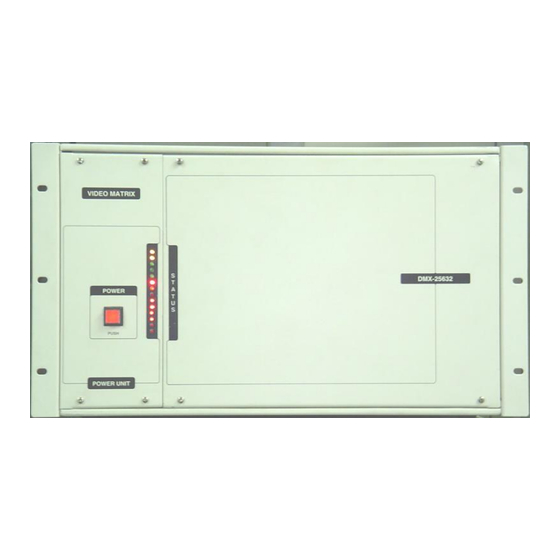
Page 8: Name Of Each Part & Its Function
Give attention to putting the card (DVC-6432) in right direction into this main CPU (DMX-25632), not to place upside down. CARD SLOT: Insert from left side and watch out for the direction. Part view side should be right. Insert cards all the way in to hear click. -
Page 9: Rear View
2 - 1 - 2. REAR VIEW CAMERA INPUT: RS-232 TERMINAL PORT: MAIN KEYBOARD: BNC which you can connect Control it by connecting PC directly Connect and Control the video cable from cameras to this port. keyboard (DCK-255). {by installing DGM-2002(Alarm map) (1-64 Cameras) or program for matrix control.} ETHERNET:... -
Page 10: Basic Configuration & Check Point
3. BASIC CONFIGURATION & CHECK POINT 3.1. BASIC CONFIGURATION MAIN KEYBOARD Connect to a keyboard controller without a Remote controlling by data junction box. networking from You can directly connect PC into distance. this port and control. (By ETHERNET CARD) *OPTIONAL- Please ask your supplier. -
Page 11: Check Point
3.2. CHECK POINT - When you connect matrix CPU (DMX-25632) with extension bay (DME-6432), follow the directions in order as below, *Matrix CPU (DMX-25632) should be arranged on Control extension bay (DME- 64 cameras & DMX-25632 6432) monitors (Main CPU unit) (16xDVC-6432 required.) -
Page 12: Full & Detailed Instructions
4.Alarm Set 1. Matrix: choose when you use a matrix switcher. 2. TX Key: Used to operate PTZ camera directly with DCK-255 with no matrix switcher (DMX-25632). <MAIN MENU> (Default value is set as this mode, TX Key) 3. Receiver Select: Select a protocol according to receiver model. - Page 13 4.Alarm Set 1. Matrix: select this when you use matrix switcher. 2. TX Key: Used to operate PTZ camera directly with DCK-255 with no matrix switcher (DMX-25632). <MAIN MENU> (Default value is set as this mode, TX Key) 3. Receiver Select: Select a protocol according to receiver model.
-
Page 14: Enter Osd Menu With Controller (Dck-255)
4.2. ENTER OSD MENU WITH CONTROLLER (DCK-255) 4.2.1 PROGRAMMING AUTO SELECTOR: Enter and press button then you will see the OSD menu on the monitor. <AUTO SELECTOR SET> NO:00 NO:00 -> The number of camera you selected. MONITOR:32 CAMERA:256 MONITOR: 32 -> Monitor No. in which you wish to input SELECT TIME:60 (e.g. - Page 15 2) Checking memorized input If you press [ENT] button on and on, you can continuously check the input value. 3) Delete programming of Auto Selector: - Delete memorized cameras in each monitor To delete memorized monitor individually hold down the [CLR] button until you hear a beep. Press monitor number and [MON] you hope to delete.
-
Page 16: Programming Alarm/ Preset
4.2.2 PROGRAMMING ALARM/ PRESET Enter button and press button, then enter into OSD <ALARM/PRESET SET>NO: 001 menu for alarm/preset. 1. PROGRAM MONITOR ALARM 1. PROGRAM MONITOR ALARM 2. SHIFT MONITOR ALARM 2. SHIFT MONITOR ALARM 3. DO YOU USE QUAD CONTROL? 3. - Page 17 Press the sensor number and [ENT] key. Repeat the steps above and press the [SET] key to save and escape. * To activate this function, never forget to press [ALARM] key. Use [CLR] to release from alarm and {ALARM} key to release its function. It is strongly recommended that you set up at once before you press the [SET] key.
-
Page 18: Id Setup On The Monitor
4.2.3 ID SETUP ON THE MONITOR: Press [ 3 ] and press [SET] button on the keyboard (DCK- 255) for ID setup on the OSD Menu. <I/D SET> 1. CHANGE SET: Correct or change camera ID. 1. ID CHANGE SET 2. - Page 19 2) Programming ID ON/OFF: Press [F/F] key to launch programming ID ON/ OFF. <I/D SET> To select monitor, move the joystick up/ down ward. MONITOR:01[ON] To select ON/OFF, move the joystick left and right. Press [F/F] button to save setup and then press [F/N] button for the previous menu, [SET] to completely escape from OSD Menu.
-
Page 20: Programming Time/ Date
4.2.4 PROGRAMMING TIME/ DATE: To enter OSD menu for TIME/ DATE SET, press [ 4 ] and [SET] button. < TIME/DATE SET> 1.TIME / DATE SET 1.TIME / DATE SET This allows you to set time, date. 2.TIME / DATE ON/OFF 2.TIME / DATE ON/OFF 3. - Page 21 2) Display TIME/ DATE On/ Off With the joystick, select ‘3. TIME/ DATE ON/OFF’ and press [F/F] to launch this menu. <TIME/DATE SET> MONITOR:01[ON] By moving the joystick upward, you can select a monitor as you desire. And by moving the joystick left and right, select ON and OFF.
-
Page 22: Caution & Trouble Shooting
5. CAUTION & TROUBLE SHOOTING 5.1. CAUTION IN USE 1. Please turn off the power before installing. 2. Please check the power after installing the system. 3. The condition of operating the system is 5℃ ~ 50℃. 4. Please be careful to shock and impact to the equipment, cause damage and failure. 5. - Page 23 6. DIMENSION CH5. DIMENSION 5-1. Dimension DMX-25632 DVC-6432 DMX-25632 CARD PCB (DVC-6432) - 23 -...
-
Page 24: Demension
7. SPECIFICATIONS 7.1. SPECIFICATIONS -DMX-25632(Video Matrix ) • System • Function -I/O Card Slot 16EA. -256By 32 Video Matrix Control -Network Card Slot 1EA. -Video Input Bay Unit Connection -Keyboard Interface (Max 3Set) -RS-232 Interface -Control up to 256 CCTV receiver... - Page 25 - 25 -...
- Page 26 - 26 -...
- Page 28 INTROD UCTION FEATU DISTRIBUTED BY...
Need help?
Do you have a question about the DMX-25632 and is the answer not in the manual?
Questions and answers