Table of Contents
Advertisement
EMPIRE
EMPIRE
Comfort Systems
Vent-Free Gas Fireplaces
This appliance may be installed in an aftermar-
ket, permanently located, manufactured (mobile)
home, where not prohibited by local codes.
This appliance is only for use with the type of
gas indicated on the rating plate. This appliance
is not convertible for use with other gases.
WARNING: If the information in these instruc-
tions are not followed exactly, a fire or explo-
sion may result causing property damage,
personal injury or loss of life.
— Do not store or use gasoline or other flam-
mable vapors and liquids in the vicinity of
this or any other appliance.
— WHAT TO DO IF YOU SMELL GAS
•
Do not try to light any appliance.
•
Do not touch any electrical switch; do not
use any phone in your building.
•
Immediately call your gas supplier from
a neighbor's phone. Follow the gas sup-
plier's instructions.
•
If you cannot reach your gas supplier, call
the fire department.
— Installation and service must be performed
by a qualified installer, service agency or the
gas supplier.
INSTALLATION INSTRUCTIONS
OWNER'S MANUAL
AND
UNVENTED
GAS FIREpLACE
MODELS
VFD26FM(2,3)0(N,W,C)-2
VFD26Fp(2,3)0L-2
VFD26Fp30L10-3
Installer:
Leave this manual with the appli-
ance.
Consumer: Retain this manual for future refer-
ence.
This is an unvented gas-fired heater. It uses air
(oxygen) from the room in which it is installed.
provisions for adequate combustion and ventila-
tion air must be provided. Refer to page 9.
WARNING: If not installed, operated and main-
tained in accordance with the manufacturer's
instructions, this product could expose you to
substances in fuel or from fuel combustion which
can cause death or serious illness.
WATER VApOR: A BY-pRODUCT OF UNVENTED
ROOM HEATERS
Water vapor is a by-product of gas combustion.
An unvented room heater produces approxi-
mately one (1) ounce (30ml) of water for every
1,000 BTU's (.3KW's) of gas input per hour. Refer
to page 8.
Page 1
Advertisement
Table of Contents

Related Manuals for Empire Comfort Systems VFD26FM20N-2


Summary of Contents for Empire Comfort Systems VFD26FM20N-2
- Page 1 INSTALLATION INSTRUCTIONS EMPIRE EMPIRE OWNER'S MANUAL Comfort Systems UNVENTED Vent-Free Gas Fireplaces GAS FIREpLACE MODELS VFD26FM(2,3)0(N,W,C)-2 VFD26Fp(2,3)0L-2 VFD26Fp30L10-3 This appliance may be installed in an aftermar- ket, permanently located, manufactured (mobile) home, where not prohibited by local codes. This appliance is only for use with the type of Installer: Leave this manual with the appli- gas indicated on the rating plate.
-
Page 2: Table Of Contents
TABLE OF CONTENTS SECTION pAGE IMPORTANT SAFETY INFORMATION ................3 SAFETY INFORMATION FOR USERS OF LP-GAS ............4 INTRODUCTION ......................5 BUILT-IN FIREPLACE INSTALLATION ................6 FIREPLACE DIMENSIONS ..................... 7 WATER VAPOR: A BY-PRODUCT OF UNVENTED ROOM HEATERS ......8 SPECIFICATIONS ...................... -
Page 3: Important Safety Information
IMPORTANT SAFETY INFORMATION THIS IS A HEATING AppLIANCE any gas control which has been under water. DANGER: Indicates a hazardous situation which, if not avoided, • You must operate fireplace with fireplace screen closed in will result in death or serious injury. place. -
Page 4: Safety Information For Users Of Lp-Gas
SAFETY INFORMATION FOR USERS OF LP-GAS Propane (LP-Gas) is a flammable gas which can cause fires by point with the members of your household. Someday when there may not be a minute to lose, everyone's safety and explosions. In its natural state, propane is odorless and will depend on knowing exactly what to do. -
Page 5: Introduction
INTRODUCTION Instructions to Installer Unvented Room Heater and should be installed according to these 1. Installer must leave instruction manual with owner after instructions. installation. Any alteration of the original design, installed other than as 2. Installer must have owner fill out and mail warranty card supplied shown in these instructions or use with a type of gas not shown on the rating plate is the responsibility of the person with unvented room heater. -
Page 6: Built-In Fireplace Installation
BUILT-IN FIREPLACE INSTALLATION Built-In Fireplace Installation Rough Opening for Installing in Corner Built-in installation of this fireplace involves installing the fireplace into a framed-in enclosure. This makes the front of the fireplace flush with a wall. If installing a mantel above the fireplace, you must follow the clearances shown in Figure 9. -
Page 7: Fireplace Dimensions
FIREPLACE DIMENSIONS GAS LINE OPENING GAS LINE JUNCTION BOX OPENING ASSEMBLY VFD26 Series Dimensions Index Letter Dimension 30 1/4" 768mm 30" 762mm 13 1/8" 333mm 18 1/8" 460mm 26" 660mm 25" 635mm 36 1/4" 921mm 36 1/4" 921mm 51 1/4" 1302mm Figure 4 27525-2-0411... -
Page 8: Water Vapor: A By-Product Of Unvented Room Heaters
SPECIFICATIONS Model VFD26F(M,P)3 VFD26F(M,P)2 VFD26FP30L10 Input Maximum 20,000 20,000 10,000 Minimum 14,000 14,000 Orifice 2.10 mm (P-288) #49 (.073") P-265 #53 (.0595") P-214 Air Shutter Opening 1/8" 1/8" 1/8" Orifice #55 (.052") P-182 #55 (.052") P-182 #64 (.036") P-193 Air Shutter Opening 1/4"... -
Page 9: Provisions For Adequate Combustion & Ventilation Air
PROVISIONS FOR ADEQUATE COMBUSTION & VENTILATION AIR This heater shall not be installed in a confined space or unusu- 3. Add the BTU/Hr of all fuel burning appliances in the space. ally tight construction unless provisions are provided for adequate Vent-free heater BTU/Hr combustion and ventilation air. - Page 10 PROVISIONS FOR ADEQUATE COMBUSTION & VENTILATION AIR VENTILATION AIR Ventilation Air From Outdoors Ventilation Air From Inside Building Provide extra fresh air by using ventilation grills or ducts. You must This fresh air would come from an adjoining unconfined space. When provide two permanent openings: one within 12"...
-
Page 11: Gas Supply
GAS SUPPLY The appliance and its individual shutoff valve must be Check all local codes for requirements, especially for the size and disconnected from the gas supply piping system during any type of gas supply line required. pressure testing of that system at test pressures in excess of Recommended Gas pipe Diameter 1/2 psig (3.5 kPa). -
Page 12: Clearances
CLEARANCES Mantel Clearances for Built-in Installation Minimum Wall and Ceiling Clearances 12” (30.5cm) MANTEL COMBUSTIBLES ALLOWED 10” (25.4cm) 11” 8” (27.9cm) (20.3cm) 10 1/4” (26.0cm) 6” 9 ½” (15.2cm) (24.1cm) 4” 8 3/4” (10.2cm) (22.2cm) 2 ½” 5 ½” (63.0cm) (14.0cm) 4 3/4”... -
Page 13: Installation Of Fireplace And Mantel
INSTALLATION OF FIREPLACE AND MANTEL Place back base and fireplace in desired location. Remove fireplace from carton. Connect gas line and electrical wiring at this time in accor- Remove mantel top and front base from mantel assembly. dance with local codes. ELECTRICAL CONNECTION OPENING... - Page 14 INSTALLATION OF FIREPLACE AND MANTEL 11. Place mantel top onto mantel assembly. Attach mantel assembly to studs in the wall through the "back brace" using two (2) 3" drywall screws provided. 12. Install outer frame. See Page 22. 13. Install fiber logs per the Log Placement Instructions. See 10.
-
Page 15: Log Placement
LOG PLACEMENT 1. Place front logs (#1 and #2) between front grate flange and Attention: Do not use Figures 12 and 13 to order logs. Refer to main burner. Align notches on front logs with locator tabs in Page 26, Parts list and Page 27, Parts View to order logs. base. -
Page 16: Placement Of Glowing Embers (Rock Wool)
Replacement of loose material (glowing embers) must be purchased wool) to be placed between logs on the flat metal surface of the from Empire Comfort Systems, Inc. Application of excess loose burner. material (glowing embers) may adversely affect performance of the heater. -
Page 17: 10,000 Btu Millivolt Lighting Instructions
10,000 BTU MILLIVOLT LIGHTING INSTRUCTIONS FOR YOUR SAFETY READ BEFORE LIGHTING WARNING: If you do not follow these instructions exactly, a fire or explosion may result causing property damage, personal injury or loss of life. A. This appliance has a pilot which must be lighted by •... -
Page 18: Millivolt Lighting Instructions
MILLIVOLT LIGHTING INSTRUCTIONS FOR YOUR SAFETY READ BEFORE LIGHTING WARNING: If you do not follow these instructions exactly, a fire or explosion may result causing property damage, personal injury or loss of life. A. This appliance has a pilot which must be lighted by •... -
Page 19: Hydraulic Thermostat Lighting Instructions
HYDRAULIC THERMOSTAT LIGHTING INSTRUCTIONS FOR YOUR SAFETY READ BEFORE LIGHTING WARNING: If you do not follow these instructions exactly, a fire or explosion may result causing property damage, personal injury or loss of life. A. This appliance has a pilot which must be lighted by C. -
Page 20: Pilot Flame Characteristics
PILOT FLAME CHARACTERISTICS Figures 15 and 18 show a correct pilot flame pattern. The correct WARNING flame will be blue and will extend beyond the thermocouple. The Never use needles, wires, or similar cylindrical objects to flame will surround the thermocouple just below the tip. A slight clean the pilot to avoid damaging the calibrated ruby that yellow flame may occur where the pilot flame and main burner controls the gas flow. -
Page 21: Main Burner And Thermostat Operation
Cleaning and Maintenance/pilot Oxygen Depletion Sensor pilot When the pilot has a large yellow tip flame, clean the Oxygen Depletion Sensor as follows: 1. Clean the ODS pilot by loosening nut B from the pilot tubing. When this procedure is required, grasp nut A with an open end wrench. -
Page 22: Outer Trim Instructions
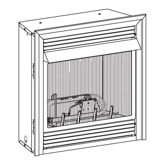
OUTER TRIM INSTRUCTIONS Remove upper louver, grasp louver at left and right ends; lift and pull forward. Open bottom louver, then lift to remove. Install the right frame and left frame to the fireplace. Align clearance holes in frame with screw holes in fireplace. Attach right frame and left frame to fireplace. -
Page 23: Millivolt Wiring
MILLIVOLT WIRING Label all wires prior to disconnection when servicing controls. Wiring 1. The remote receiver can not be placed behind the gas valve errors can cause improper and dangerous operation. Verify proper and burner assembly. operation after servicing. 2. When facing the appliance, the remote receiver must be placed to the right of the gas valve and burner assembly. -
Page 24: Junction Box Wiring Installation Instructions
JUNCTION BOX WIRING INSTALLATION INSTRUCTIONS CAUTION: ALL WIRING SHOULD BE DONE BY A qUALIFIED ELECTRICIAN AND SHALL BE IN COMpLIANCE WITH ALL LO- CAL, CITY AND STATE BUILDING CODES. BEFORE MAKING THE ELECTRICAL CONNECTION, MAKE SURE THAT MAIN pOWER SUppLY IS DISCONNECTED. THE AppLIANCE, WHEN INSTALLED, MUST BE ELECTRICALLY GROUNDED IN ACCORDANCE WITH LOCAL CODES OR, IN THE ABSENCE OF LOCAL CODES, WITH THE NATIONAL ELECTRICAL CODE ANSI/NFpA 70 (LAT- EST EDITION). -
Page 25: Troubleshooting
TROUBLESHOOTING SYMPTOMS, POSSIBLE CAUSES AND CORRECTIONS Turn appliance OFF and allow to cool before servicing. Only a qualified service person should service and repair the heater. 1. When ignitor button is pressed, there is no spark at ODS/ couple to cool, causing pilot flame to go out. This problem pilot. -
Page 26: Parts List
P182 ORIFICE 23496 TUBING ASSEMBLY 23493 TUBING ASSEMBLY R3436 SWITCH, REMOTE/OFF/ON R3625 VALVE R10947 WIRE ASSEMBLY 23496 TUBING ASSEMBLY NS - NOT SHOWN R3436 SWITCH, REMOTE/OFF/ON Page 26 27525-2-0411 Empire Comfort Systems, Inc. Nine Eighteen Freeburg Ave. Belleville, Illinois 62220-2623... -
Page 27: Parts View
PARTS VIEW 27 28 5 PIECE LOG ASSEMBL MILLIVOLT VALVE ASSEMBL THERMOSTATIC VALVE ASSEMBL 27525-2-0411 Page 27... -
Page 28: Fbbx Blower Kit Extension Installation Instructions
FBBX BLOWER KIT EXTENSION INSTALLATION INSTRUC- TIONS For Unvented Gas Fireplace Model VFD26F(M,p)2, VFD26F(M,p)3 Disregard FBB4 Blower Installation Instructions. Follow the in- Blower Wheels stallation instructions with your FBBX blower extension kit or the The blower wheels will collect lint and could require periodic clean- VFD26 Instruction Manual. -
Page 29: Fbb4 Optional Variable Speed Blower
FBBX BLOWER KIT EXTENSION INSTALLATION INSTRUCTIONS (cont.) 11508 SWITCH BRACKET R-9377 HARNESS R-1131 SCREWS R-2737 #10 X 1/2 SCREWS FBBX Blower Kit 110 VOLT AC JUNCTION BOX BLACK WHITE SWITCH BLACK SWITCH BRACKET WHITE GROUND SPEED CONTROL FBBX Wiring Diagram FBB4 OpTIONAL VARIABLE SpEED BLOWER FBB4 BLOWER ASSEMBLY... -
Page 30: Fpp26E Optional Brick Liner Kit Installation Instructions
FPP26E OPTIONAL BRICK LINER KIT INSTALLATION INSTRUCTIONS Remove screen from fireplace. Remove branch log and rear log from burner assembly. Insert back panel into firebox. Insert one (1) side panel into firebox. Align clearance hole on brick panel bracket with screw hole in the left or right interior top of firebox. Use two (2) 10 x 1/2" screws to attach brick panel bracket to interior, top of firebox. -
Page 31: Master Parts Distributor List
This list changes from time to time. For the current list, please click on the Master Parts button at www.empirecomfort. com. Please note: Master Parts Distributors are independent businesses that stock the most commonly ordered Original Equipment repair parts for Heaters, Grills, and Fireplaces manufactured by Empire Comfort Systems Inc. Dey Distributing East Coast Energy products... - Page 32 Empire Comfort Systems Inc. EMPIRE EMPIRE 918 Freeburg Ave. Belleville, IL 62220 If you have a general question about our products, please e-mail us at info@empirecomfort.com. If you have a service or repair question, please contact your dealer. Comfort Systems www.empirecomfort.com...
Need help?
Do you have a question about the VFD26FM20N-2 and is the answer not in the manual?
Questions and answers