
Related Manuals for VAC Statement 450


Summary of Contents for VAC Statement 450
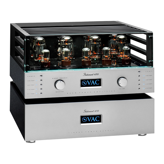
- Page 1 The VAC Statement 450 Mono Beam Power Amplifier Operation & Maintenance Information Valve Amplification Company Manual issued 09/22/2010 Revised 01/19/2011 Revised 07/26/2011...
- Page 2 CAUTION - SAFETY NOTICE THE AMPLIFIER AND POWER SUPPLY CONTAIN NO USER SERVICEABLE PARTS. DO NOT REMOVE THE BOTTOM PLATES OR CHASSIS COVERS. LETHAL VOLTAGES ARE PRESENT WITHIN THE CHASSIS. DO NOT OPERATE THE UNITS IF THEY ARE WET. VACUUM TUBES BECOME HOT ENOUGH TO CAUSE SERIOUS BURNS. NEVER TOUCH A TUBE WHEN THE UNIT IS ON.
- Page 3 INDEX Introduction Installation Installing the front glass and top bars Input connectors Operation Illuminated Logo Installing New Output Tubes Biasing & Checking Output Tube Condition Replacement of Low Level Tubes Care Of Chassis Tips and Advice Fuses A Word About Tubes in General Output Tubes Low Level Tubes Impedance Matching...
- Page 4 INTRODUCTION The Statement 450 is a unique power amplifier, and the most powerful and detailed in VAC’s history. Featuring a new direct-coupled input & driver circuit, extremely fast and vivid sound is achieved from both single-ended and balanced sources. The front panel attenuator may be selected for aid in balancing channels. It may also be used to trim spectral balance when biamplifying.
-
Page 5: Installation
INSTALLATION Place the power supply in its final location. It is quite heavy, and will become more so when the amplifier is installed on top of it. Consider the location carefully, and use appropriate help in lifting, etc., so as to avoid injury. Place one of the metal balls provided in each of the three cups on the top of the power supply. - Page 6 Provide adequate ventilation - allow at least 3 inches above and to each side. Do not place in a completely enclosed cabinet. Do not stack other equipment on top of the VAC unit. Do not operate on carpet or any other surface that might block air flow.
- Page 7 Connect the power cord to the power source indicated on the rear panel (will be either 100, 120, 220, or 240 volts AC). Voltage conversions must be done at the factory of by an authorized VAC importer. Avoid power conditioners that float the ground pin.
- Page 8 INSTALLING THE FRONT GLASS AND TOP RAILS Your amplifier has been shipped with the front glass and the top rails removed. The following steps show how these are installed. Lay the provided microfiber cloth on top of the fascia as shown. Set the glass in place.
- Page 9 The top tube cage bars have a spring pin in each end. To install, place one of the spring pins into one of the small dimples machined into one of the side rails. In the Illustration, the pin has been located into the left side rail. To complete the installation, press the bar in the direction of the pin already inserted, and manoeuver the other end into the corresponding dimple in the other side rail, then release.
-
Page 10: Operation
3,000 to 8,000 hours. For best tube life, turn the amplifier off when you are not listening. Any time that the VAC Power Amplifier has not been used for a few weeks the sound may be different. This is also normal for high resolution audio equipment. Optimum sound should return after a few hours of operation, preferably with an audio signal. - Page 11 First, see the SAFETY NOTICE earlier in the manual. Output tubes are type KT88. Replacement output tubes should be purchased from VAC. It is desirable that tubes be in matched quartets for each channel, and be close to the "bogey" values for the major parameters.
- Page 12 CHECKING OUTPUT TUBE CONDITION / OUTPUT TUBE BIAS ADJUSTMENT Bias settings it should be checked when you install your amplifier and approximately once every month thereafter. It must also be adjusted each time a tube is replaced. The condition of the individual KT88 output tubes is checked using the TEST switch and eight built in indicator lights (four on each side of the front panel, adjacent to the adjustment points..
-
Page 13: Care Of Chassis
Therefore we recommend obtaining replacement tubes from VAC, specifying that they are for use in the Statement 450 amplifier. For further information, refer to Tips & Advice: A Word About Tubes in General and Tips & Advice: A Word About Low Level Tubes. - Page 14 TIPS & ADVICE SECTION Tips: Fuses Your amplifier is designed to use “slow blow” type fuses. These are contained in the fuse drawer built into the power receptacle. In the fuse drawer are two fuses. The one furthers in is the active fuse. The one nearer to the outside is a spare.
- Page 15 In normal use, output tubes will last at least 2 years and perhaps more than 5 years. It is normal to see a slight violet glow in a power tube such as a KT88. However, a vivid violet indicates excess current flow through the tube and should be investigated. VAC can test tubes for concerned customers.
- Page 16 Your VAC Amplifier uses the KT88 kinkless tetrode. It is strongly recommended that replacement tubes be purchased only from VAC. If, however, you want to customize the sound to your tastes, be aware that as with interconnects and speaker cables, each tube manufacturer's KT88 tends to have a distinct sound, as well as its own reliability profile.
- Page 17 Contrary to popular misconception, no power is lost due to unused output taps. For more information consult VAC Technical Monograph 90-9, which may be viewed on our wesite (http://www.vac-amps.com).
- Page 18 Keep the audio cables as close together as possible. Keep the AC cords away from the audio cables. Try different ground settings on your preamplifier, if it has them. For example, the VAC Signature, Phi, and Renaissance preamplifiers may be set to “ungrounded” or “XLR” audio modes.
-
Page 19: Specifications
SPECIFICATIONS The VAC Statement has been developed with the critical ear as the major arbiter of quality, with both conventional and unique measurements providing insight and guidance as necessary. The lack of emphasis on measurements is due to the fact that engineering's arsenal of equipment and techniques do not operate on the pattern recognition principals that control human perception of sound. -
Page 20: Warranty
Your equipment is warranted for a period of thirty (30) days from the date of purchase. In addition, if the registration form is received by VAC along with a copy of your sales receipt from an authorized VAC dealer within this thirty days, the warranty will be extended to two (2) years (tubes excepted). This warranty applies only to units sold in the United States of America through authorized VAC dealers and operated within the United States by the original purchaser.
Need help?
Do you have a question about the Statement 450 and is the answer not in the manual?
Questions and answers