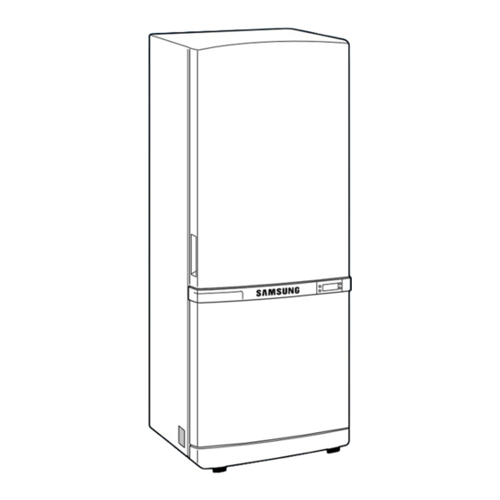
Samsung RB1855SW Service Manual

Samsung RB1855SW Service Manual

Bottom-mounted freezer
Hide thumbs Also See for RB1855SW:

Advertisement

SAMSUNG Home Appliance Service
Model:
Bottom-Mounted Freezer
RB1855SW
RB1855SL
RB2055SW
RB2055SL

Advertisement

Table of Contents
loading

Summary of Contents for Samsung RB1855SW

  • Page 1 SAMSUNG Home Appliance Service Model: Bottom-Mounted Freezer RB1855SW RB1855SL RB2055SW RB2055SL...
  • Page 2 The manufacturer or dealer cannot be responsible for the interpretation of this informatio All rights reserved. This service guide may not be reproduced in whole or in part in any form without written permission from the SAMSUNG ELECTRONICS Company.
  • Page 3: Table Of Contents

    Contents 1. Installation ······································ 2. Nomenclature ···································· 3. Product Specifications ······························· 4. Electrical part specifications & standard ····················· 5. Interior Views and Dimensions ··························· 6. Refrigeration Cycle and Cool Air Circulation Route ··············· 7. Mechanical Disassembly ······························ 8. Operation Function ·································...
  • Page 4: Installation

    1. INSTALLATION 1) To protect refrigerator in movement Use padded hand truck from side only. 2) Remove all protective tape and pad from the refrigerators. Connect power cord. Adjust the clearance between the doors. 3) Temperature controls ard preset in the factory for recommended settings.
  • Page 5: Product Specifications

    3. PRODUCT SPECIFICATIONS Model RB1855SW RB1855SL RB2055SW RB2055SL Type BMF 2 Door Temperature control Electronic control Total 506 (18.7) 556 (20.4) Net Capacity Freezer 143 (5.9) 161 (6.5) LT(ft 363 (12.8) 395 (13.9) Refrigerator Net dimension 1775(mm) 1775(mm) Cabinet insulation...
  • Page 6 ELECTRICAL PART SPECIFICATIONS & STANDARD ITEM STANDARD Type Temperature Selection ON(℃) OFF(℃) –25℃ -23.5℃ -26.5℃ Freezer F-Sensor –19℃ -17.5℃ -20.5℃ -14℃ -12.5℃ -15.5℃ Type Temperature Selection ON(℃) OFF(℃) 1℃ 2.5℃ -0.5℃ Refrigerator R-Sensor 4℃ 5.5℃ 2.5℃ 7℃ 8.5℃ 5.5℃ First Defrost Cycle 4hr ±10min (Concurrent Defrost of F and R) Defrosting...
  • Page 7: Interior Views And Dimensions

    5. Interior Views and Dimensions 5-1) Shelves and Bins • Deli drawer • Door Bin Pull it out to disassemble. Push it up and slide it out to disassemble. Light • • • • Gallon Bin • Glass Shelf • Pull it out until its stop Tilt down and slide it out.
  • Page 8 Interior Views and Dimensions 5-2) Dimensions of Refrigerator (mm) MODEL RB1855 1468 RB2055 1518...
  • Page 9: Refrigeration Cycle And Cool Air Circulation Route

    6. Refrigeration Cycle and Cool Air Circulation Route 6-1) Refrigerant Route in Refrigeration cycle Compressor → Sub condenser → Cluster pipe → Hot pipe → Dryer → Capillary tube → R-Evaporator → F-Evaporator → Accumulator → Suction pipe → Compressor...
  • Page 10 Refrigeration Cycle and Cool Air Circulation Route 6-2) Cool Air Circulation...
  • Page 11: Mechanical Disassembly

    7. Mechanical Disassembly Refrigerator Disassembly Control Panel ········································ Refrigerator Light ······································ Freezer Light ········································ Evaporator Cover in the Refrigerator ·························· Evaporator Cover in the Freezer ····························· Evaporator in the Refrigerator ······························· Evaporator in the Freezer ································· Machine Compartment & Electric Box ··························...
  • Page 12: Control Panel

    Mechanical Disassembly Control Panel 1. Remove the screws. 2. Pull out the control panel. 3. Disconnect the wire connector.
  • Page 13: Refrigerator Light

    Mechanical Disassembly Always unplug the power cord before replacing the refrigerator lamp. There is the danger of electric shock. Warning Refrigerator Light Freezer Light 1. Remove the cover by pressing the bottom tab. 1. Remove the screw. 2. Remove the lamp cover by unlocking the tabs and pulling the cover down.
  • Page 14: Evaporator Cover In The Refrigerator

    Mechanical Disassembly Evaporator Cover in the Refrigerator 6. Disconnect the wire connector. 1. Remove all shelves and drawers from the refrigerator. 2. Pull out the screw caps with a small flat-blade screwdriver. 3. Remove 6 Phillps screws from the cover. ■Ductwork of the evaporator fan assembly.
  • Page 15: Evaporator Cover In The Freezer

    Mechanical Disassembly Evaporator Cover in the Freezer 5. Disconnect wire connector from the top-left 1. Remove all drawers from the freezer. corner. 2. Remove screws (2) from the support rail. 6. Remove 2 screws from the rear cover of the freezer evaporator and unlock the tabs to remove it.
  • Page 16: Evaporator In The Refrigerator

    Mechanical Disassembly Evaporator in the Refrigerator Evaporator in the Freezer Evaporator is located in the bottom of refrigerator. Evaporator is located in the bottom of freezer to 1. Take off the ductwork in refrigerator. produce cold air driven across the evaporator coils. 2.
  • Page 17: Machine Compartment & Electric Box

    Mechanical Disassembly Machine Compartment & & Electric Box 3. Machine compartment assembly Make sure the power cord is unplugged before replacing any electric components. Warning 1. Unplug the power cord. 4. Disassemble the electric box cover after removing the screws with a screwdriver. 2.
  • Page 18: Operation Function

    8. Operation Function 8-1) Display design ·································· 8-2) Temperature Control Function ························· 8-3) Buzzer alarm function ····························· 8-4) Defrosst function ································· 8-5) Test function ··································· 8-6) Function of initial Power ON ·························· 8-7) Power failure compensating Function ····················· 8-8) Self-test function ·································...
  • Page 19: 8-1) Display Design

    Operation Function 8-1) Display design 8-2) Temperature control function 1) Temperature selection of freezer compartment ❈ After the initial key selection, it displays the notch which is presently set up, then within 5 seconds re-memorize the key after 1-2) points mentioned below. If there is no input of the key, it moves back to the previous temperature display.
  • Page 20 Operation Function 3) Quick freeze 3-1) Press the on/off buttons of Quick Freeze so that the lamp of Quick Freeze is light up and off and then it operates it’s function automatically. 3-2) It does not indicate from initial Power on. Initial Power On Pressed once time Pressed second time...
  • Page 21: 8-3) Buzzer Alarm Function

    Operation Function 5) Sabbath function 5-1) It will turn to sabbath function if you press freezer and refrigerator temperatune button together for 5 seconds. 5-2) When turned to sabbath function, all of the front display of LED turn off. 5-3) The light will not switch on even when the door is opened, and if it was switched on then it will switch off.
  • Page 22: 8-5) Test Function

    Operation Function 10) Heater off is decided by accumulated heater on time During defrost, the defrost heater of freezer is off, when the heater on time becomes 70 • minutes. During defrost, the defrost heater of refregerator is off, when the heater on time becomes 80 •...
  • Page 23: 8-8) Self-Test Function

    Operation Function ❈ Exhibition mode This function is for a display purpose on the floor of show room or store. 1) Mode ON/OFF 1-1) For the exhibition mode, press Quick Freeze and Freezer Temp. buttons simultaneously for 5 seconds until a “ding-dong” sounds. 1-2) Press the same time buttons again for 5 seconds to cancel this mode put with a “ding- dong”...
  • Page 24: 8-9) Display Function Of The Presently Operating Parts

    Operation Function Table 1. Display table of self diagnosis. FREEZER:10digit FREEZER: 1digit REFRIGERATOR:10digit REFRIGERATOR: 1digit Item Display LED Symptom Remark ˚C Refrigerator • Open faulty •Suspected to be below -50 R-sensor 1 digit “b” led • Short faulty ˚C •Suspected to be over +65 R-area ˚C Refrigerator...
  • Page 25: 8-10) Actual Temperature And Selected Temperature In Display Function

    Operation Function 2) At this moment if you take off quick freeze and quick cool button and press refrigerator temp. button (ding-dong sound), it change into the display of the presently operating parts. 3) This display condition is unrelated to actual operation and it is an reference of indication that MICOM commanded operating order).
  • Page 26 Operation Function 3) Door open when door is open, the related display shows an actual temperature. 3-1) Display range of freezer is -35 ~ 30 and refrigerator is -9 ˚C ˚C ˚C ˚C 3-2) If freezer inner temperature is above 0 for 10 minute, the display of the selected temp.
  • Page 27: Circuit Descriptions

    9. Circuit Descriptions 9-1) Power Circuit ····································· 9-2) Oscillator ········································ 9-3) Reset Circuit ······································ 9-4) Door S/W Circuit ···································· 9-5) Temperature Sensor ································· 9-6) Button Scan and Display Circuit ··························· 9-7) Load Operation ···································· 9-8) Other Option Functions ································...
  • Page 28: 9-1) Power Circuit

    Circuit Descriptions 9-1) Power Circuit Circuit used Voltage Relay Operation & LED Display (DC 12V) Power around MICOM & Sensor Detector Vcc (DC 5V) 1) The input AC voltage of DC-trans secondary registers 8V at CN10 between ①~③. The rectified voltage passed through D101 ~ 104 becomes DC 5V through voltage regulator MC7805(REG1).
  • Page 29: 9-3)Reset Circuit

    Circuit Descriptions 9-3)Reset Circuit When power is supplied to MICOM, reset circuit initializes RAM and other parts on MICOM to initialize all programs. Reset voltage maintains “low” for hundreds of µsec comparing to MICOM Vcc voltage when power is input. It also maintains “high”(5V) during normal operation.
  • Page 30: 9-5) Temperature Sensor

    Circuit Descriptions 9-5) Temperature Sensor ( Air Sensor) When Sensor is open When sensor is cut off MICOM input “HIGH” MICOM input “LOW” 1) The sensor uses the characteristics of thermistor. If temperature goes higher, resistance goes lower. On the contrary, if temperature goes lower, resistance goes higher. 2) MICOM input voltage is counted by sensor as follows.
  • Page 31: 9-6) Button Scan And Display Circuit

    Circuit Descriptions 9-6) Button Scan and Display Circuit If the IC04 decorder(KID65783AD) receives signals from MLCOM pins(34-6), an output signal per 2 miliseconds comes out from Grid#1-#7. A step DC12 volt peak will be generated periodically as follows:...
  • Page 32: 9-7) Load Operation

    Circuit Descriptions 9-7) Load Operation 1) Most of relays can control the compressor, heaters and several option functions. 2) For the compressor, #12 pin of MICOM signals HIGH(5V). This signal enters to #2 of IC03 and #15 of output terminal will be on and grounded. When the rely RY71 is switched to NO terminal a 115V power is supplied to the compressor.
  • Page 33: 9-8) Other Option Functions

    Circuit Descriptions 9-8) Other Option Functions Temperature and function values can be abjustable by using main PCB switching diode. : the values have been preset in factory. If is recommended not to change the value arbitrarily. • Note When the option function is modified, a power should be turned off and on, again. 1) Freezer Temperature Shift 2) Refrigerator Temperature Shift (Unit ˚C)
  • Page 34 Circuit Descriptions...
  • Page 35: Diagnostics

    10. Diagnostics 10-1) If power is not ON Caution! To check the main PCB, please apply descriptions of At the power of main PCB, the 115V power and a high- operation and references in voltage over DC 170V occur. Special care should be the manual.
  • Page 36 Diagnostics 10-2) If there is a trouble with self-diagnosis 1) If the ambient sensor has trouble. 2) If the temperature sensor of the refrigerator has trouble.
  • Page 37 Diagnostics 3) If the defrost sensor of the refrigerator has trouble. 4) If the temperature sensor of the freezer has trouble.
  • Page 38 Diagnostics 5) If the defrost sensor of the freezer has trouble.
  • Page 39 Diagnostics 10-3) If the compressor is not working properly Pre-check 1. A compressor does not operate within 5 minutes after compressor is OFF. 2. A compressor does not run during defrost period 3. A compressor does not run because a low temperature is detected if freezer and the refrigerator sensor are not connected.
  • Page 40 Diagnostics 10-4) If cooling fan doesn’t work Pre-check Select a pull-down mode from the forced operation function 1. When COMP is OFF both freezer and the refrigerator cooling fans and COMP cooling fan remain OFF. 2 . When COMP is ON, the refrigerator fan is not always ON and when the refrigerator temperature reached a set temperature, the fan goes OFF.
  • Page 41 Diagnostics 10-5) If the refrigerator fan doesn’t work...
  • Page 42 Diagnostics 10-6) If the compressor cooling fan motor doesn’t work...
  • Page 43 Diagnostics 10-7) No defrosting Pre-check 1. Although both F R-defrost sensors have short-circuit, a normal operation continues without a defrost cycle (Refer to self - diagnostics function) 2. When the temperature fuse is open, there is no heating and a defrost occurs naturally by the compartment temperature increase and eventually, it will cause a blinking of temperature.
  • Page 44 Diagnostics...
  • Page 45 Diagnostics 10-8) Alarm continuously Pre-check 1. Alarm begins after 2 minutes when the door is open and runs in every 2 minutes. 2. If the door is not closed properly, MICOM will indicate that the door is open, and alarm continues.
  • Page 46 Diagnostics 2) If beep sounds continuously 3) When the digital panel PCB does not light...
  • Page 47 Diagnostics 4) When a button of the digital panel is not selected...
  • Page 48 Diagnostics Pre-check 1. Is the power cord connected to a wall outlet correctly? 2. Be careful of high-voltage, high-frequency discharge from the electronic ballast. 5) If the lamp of refrigerator fails to light...
  • Page 49: Illustrated Parts Catalog

    11 . Illustrated Parts Catalog. 11-1) Freezer...
  • Page 50 Illustrated Parts Catalog. ■ ■ Parts List of Freezer OPTION CODE-NO PART NAME SPEC RB1855 RB2055 DA67-40203N TRAY-ICE,ASSY DA67-40182A TRAY ICE DA97-00682A TRAY-FRE UPP,ASSY DA97-00682B TRAY-FRE UPP,ASSY DA63-01260A COVER-TRAY FREE, UPP DA97-00683A TRAY-FRE MID,ASSY DA97-00683B TRAY-FRE MID,ASSY DA63-01272A COVER-TRAY FREE, MID DA97-00684A TRAY-FRE LOW,ASSY DA97-00684B...
  • Page 51 Illustrated Parts Catalog. 11-2) Refrigerator...
  • Page 52 Illustrated Parts Catalog. ■ Parts List of Refrigerator OPTION CODE-NO PART NAME SPEC RB1855 RB2055 CASE-VEG,ASSY DA97-00681A DA97-00681B CASE-VEG,ASSY DA63-01270A COVER-VEG KNOB-HUMIDITY DA64-00656A ROLLER FRE DA66-10104A DA71-20145A FIXER ROLLER DA61-00761A RAIL-VEG, MID RAIL-VEG, MID DA61-00760A COVER-VEG ASSY DA97-00663A COVER-VEG ASSY DA97-00663B DA64-00449A TRIM-COVER,VEG...
  • Page 53 Illustrated Parts Catalog. 11-3) Disassembly of Door...
  • Page 54 Illustrated Parts Catalog. ■ Parts List of Freezer Door OPTION CODE-NO PART NAME SPEC 1855SW/2055SW 1855SL/2055SL DA91-01466Q ASSY FOAM-DOOR REF SNOW WHITE DA91-01466R ASSY FOAM-DOOR REF NOBLE-GRAY DA71-40135A STOPPER DOOR, MID DA71-40183C STOPPER DOOR-LOW SNOW WHITE DA71-40183M STOPPER DOOR-LOW NOBLE-GRAY DA91-01468A ASSY FOAM-DOOR FRE SNOW WHITE...
  • Page 55 Illustrated Parts Catalog. 11-4) Cabinet...
  • Page 56 Illustrated Parts Catalog. ■ Parts List of Cabinet OPTION CODE-NO PART NAME SPEC 1855SW/2055SW 1855SL/2055SL DA61-10145D HINGE-LOW DA64-20138B TRIM-PLATE,ABSORBER DA63-10262F COVER-LEG SNOW WHITE DA63-10262P COVER-LEG NOBLE GRAY DA34-00122D SWITCH DOOR CASE-PCB PANEL DA61-00758A DA67-30218R CAP-SCREW SNOW WHITE DA67-00322K CAP-SCREW NOBLE GRAY DA26-30111J TRANS POWER 2501-001045...
  • Page 57: Appendix Ⅰ Ⅰ (Reference For Circuit Diagnostics)

    Appendix Ⅰ Ⅰ (Reference for circuit diagnostics) Ref.1) Wire connector on the cabinet door. Ref. 2) How to check relay failure * Disconnect the wire connector from the main PCB CN70, 71 and measure the following items. 1. Measure the coil bisection of the relay and check whether it works.
  • Page 58 Ref. 3) Check a load * Unplug the power cord and disconnect the connector from the main PCB CN70, 71 and measure the following: 1. Measure resistance between the terminals and check for malfunctioning of a load and wire connection. Measurement Evaluation of mea- Subordinate...
  • Page 59 Ref. 5) Check Door S/W (Refrigerator Bulb) 1. Open the door and check if the freezer lamp turns on. 2. Press the Door S/W and check if the freezer lamp turns off. 3. Close the freezer door and repeat 1 and 2 for refrigerator door.
  • Page 60 Ref. 7) Table of temperature sensor according to resistance and voltage conversion. * Voltage conversion table depends on H/W structure of MICOM port input voltage. Sensor Short : Micom 0V. Sensor Open : Micom 5V. ※ Sensor partial pressure resistance 10KΩ Voltage(V) Voltage(V) Voltage(V)
  • Page 61: Appendix Ⅱ Ⅱ (Circuit Diagram)

    Appendix Ⅱ Ⅱ (Circuit diagram)
  • Page 62: Safety Instruction On Services

    12. Safety Instructions on Service ●Unplug the refrigerator before making any repair or any replacement. Avoid the electric shock. ●Use the rated components on the replacement. Check the correct model number, rated voltage, rated current, operating temperature and so ●On repair, be sure that the wires such as harness are bundled tightly and are not exposed by water.
  • Page 63 ELECTRONICS 272, Oseon-Dong, Kwangsan-Gu, Kwangju-City, Korea, 506-723 TEL : 82-62-950-6896, 6193 FAX : 82-62-950-6829 © Samsung Electronics Co., Ltd. Refrigerator Division 2003. 05 Printed in Korea Code-No : DA68-01291A REV(0.0)

This manual is also suitable for:

Rb1855slRb2055swRb2055sl

Table of Contents