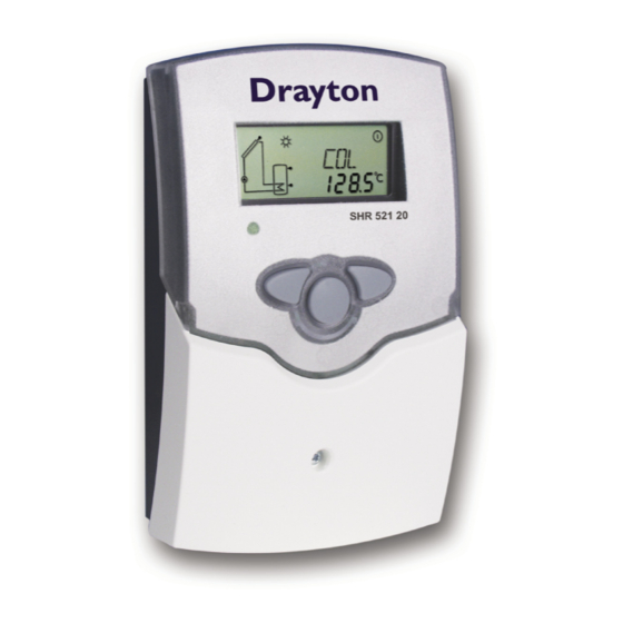
Summary of Contents for Drayton SHR 521 20
- Page 1 Drayton SHR 521 20 Installation Commissioning Operation Fault finding Examples manual Thank you for buying a Drayton product. Please read this manual carefully to get the best perfomance from this unit.
-
Page 2: Table Of Contents
SHR 521 20 Contents Disclaimer ................2 2.2.3 System screen................. 8 Safety Regulations...............2 Flashing symbols..............8 Technical data and function ..........3 2.3.1 System-Screen flashing symbols ......... 8 Installation .............5 2.3.2 Flashing symbols..............8 Mounting.................. 5 Commissioning............9 Electrical wiring..............5 Control parameter and indication channels ... 10 1.2.1... -
Page 3: Technical Data And Function
Parts included: 1 x SHR 521 20 1 x accessory bag 1 x spare fuse T4A 2 x screws and wall plugs 4 x cable clamps and screws Additionally enclosed in the full kit:... - Page 4 SHR 521 20 Examples SHR 521 20 Standard solar systems Solar systems with dual-mode DHW cylinder Please find detailed con- nection diagramms for these systems in chap- ter 1.
-
Page 5: Installation
SHR 521 20 Installation display Warning! 1.1 Mounting Switch-off mains supply before opening the housing. The unit must only be located indoors. It is not suitable for installation in hazardous locations and should not be cover sited near to any electromagnetic field.The controller must... -
Page 6: Standard Solar System
SHR 521 20 1.2.1 Allocation of terminals for system 1 Standard solar system with 1 store, 1 pump and 3 sen- sors. The sensor S4 / TRF can optionally be used for heat quantity balancing. Arr 1 Symbol Specification Collector sensor... -
Page 7: Operation And Function
SHR 521 20 Operation and function 2.1 Pushbuttons for adjustment The controller is operated by 3 pushbuttons below the display. The forward-key (1) is used for scrolling forward through the menu or to increase the adjustment values. The backwards-key (2) is accordingly used for the reverse function. -
Page 8: System Screen
SHR 521 20 2.2.3 System screen The system screen (active system scheme) shows the schemes selected on the controller. It consists of several system component symbols, which are - depending on the current status of the system - either flashing, permanently shown or hidden. -
Page 9: Commissioning
SHR 521 20 3. Commissioning To commission you have to adjust the solar thermal system 1.Ac power supply must be activated.The controller passes an initialisation phase in which the operating control lamp flashes red and green. When the initialisation is complete,... -
Page 10: Control Parameter And Indication Channels
SHR 521 20 Control parameters and menu mode 4.1 Mode-overview Legend: Corresponding mode is only available if the option heat Corresponding mode is available. quantity measurement is activated (OWMZ). Corresponding mode is available if the appropriate option Corresponding mode is only available if the option heat is activated. -
Page 11: Indication Channels
SHR 521 20 4.1.1 Indication of collector temperatures Shows the current collector temperature. COL: Collector temperature • COL : collector temperature (1-collector-system) display range: -40 ...+250 °C 4.1.2 Indication of store temperatures Shows the current store temperature. TST,TSTL,TSTU: Store temperatures •... -
Page 12: Adjustment Channels
SHR 521 20 4.1.6 Heat quantity balancing OHQM:Heat quantity balan- Heat quantity balancing is possible for all systems in conjunc- cing tion with a flowmeter.You just have to activate the option Adjustment range: OFF ...ON heat quantity balancing in the mode OHQM. -
Page 13: S Mx
SHR 521 20 4.1.7 ∆T -adjustment DT O: Basically the controller works in the same way as a standard Switch-on temperature differential controller. If the switch-on difference (DT O) Adjustment range 1,0...20,0 K is reached, the pump is activated. If the selected switch-off Factory setting 6.0... -
Page 14: Ocx
SHR 521 20 4.1.9 Collector temperature limit If the selected collector limit temperature (EM) is exceeded, Collector emergency shutdown the solar pump (R1/R2) is deactivated to avoid overheating of the solar components (collector emergency shutdown). The limit temperature is set to 140 °C but it can be changed within the adjustment range of 110 ...200 °C. -
Page 15: Orec
SHR 521 20 4.1.13 Recooling function If the selected maximum store temperature (S MX) is reached, the solar pump remains activated to avoid OREC: overheating the collector. The store temperature might option recooling continue to increase but only up to 95 °C (emergency adjustment range shutdown of the store). -
Page 16: Hnd2
SHR 521 20 4.1.16 Operating mode For commissioning and service work the operating mode HAND / HND1 / of the controller can be manually selected by selecting the HND2: adjustment value HAND / HND1 / HND2, in which the Operating mode... -
Page 17: Tips For Fault Finding
SHR 521 20 5.Tips for fault finding can fuse T4A If a malfunction occurs, a notification is given on the display of the controller: 220 ... 240 V~ 2 (1) A (220 ... 240) V~ Temp. Sensor 2 (1) A (220 ... 240) V~... -
Page 18: Miscellaneous
SHR 521 20 5.1Various: Pump is overheated, there is no heat transfer from coll- Pump starts for a short moment, switches off, switches on ector to the store, feed flow and return flow are equally again, etc. (“controller hunting“) warm, perhaps also bubble in the lines. - Page 19 SHR 521 20 Stores are cooled during the night. Control the return flow Please also check further preventer in warm water pumps which are connec- circulation- o.k. ted to the solar store. Does collector circuit pump run during the night? Check the controller Cleaning or replacement.
-
Page 20: Accessories
SHR 521 20 6.Accessories Sensors Our product range includes high-precision platinum tem- perature sensors, flatscrew sensors, ambient temperature sensors, indoor temperature sensors, cylindrical clip-on sensors and irradiation sensors, which can be used as full sensors with sensor pocket. Overvoltage protection We highly recommend installing overvoltage protection in order to avoid overvoltage damage to the collector (e.g.


Need help?
Do you have a question about the SHR 521 20 and is the answer not in the manual?
Questions and answers