Table of Contents
Advertisement
Quick Links
MOWER LAND
MOWER AND TILLER
L
MODEL MLTILL 5
OPERATOR' S MANUAL
Before operating this appliance, please ensure that you read & understand all
the instructions that apply to it, as failure to comply wih these instructions
may result in personal injury to other persons, and also increase the risk of
fire. Please ensure that any replacement parts or accessories used with this
appliance are correctly and/or securely fitted before use.
Please retain these instructions for constant reference.
Advertisement
Table of Contents

Summary of Contents for Mower Land MLTILL5
- Page 1 MOWER LAND MOWER AND TILLER MODEL MLTILL 5 OPERATOR' S MANUAL Before operating this appliance, please ensure that you read & understand all the instructions that apply to it, as failure to comply wih these instructions may result in personal injury to other persons, and also increase the risk of fire.
-
Page 2: Table Of Contents
TABLE OF CONTENTS Specifications Introduction Engine B&S QUANTUM 60 Specifications 500mm Cultivating Width Symbols 250mm Cultivating Depth Safety 120rpm Tine Speed General Safety Rules 42.5kg Weight Specific Safety Rules 96 dB(A) Sound power level Contents supplied 79.3 dB Sound pressure level Assembly * Measured according to 2000/14/EC Know your tiller... -
Page 3: Safety
Never operate the machine when it is in need of SAFETY repair or is in poor mechanical condition. Replace General Safety Rules damaged, missing or failed parts before using it. Check for fuel leaks. Keep the machine in safe working condition. Understand your machine Never tamper with safety device. - Page 4 Always stop the engine and allow it to cool before Avoid contact with hot fuel, oil, exhaust fumes and filling the fuel tank. Never remove the cap of the hot surfaces. Do not touch the engine or muffler. fuel tank or add fuel while the engine is running These parts get extremely hot from operation.
-
Page 5: Specific Safety Rules
Be careful when tilling in hard ground. The tines Specific Safety Rules may catch in the ground and propel the tiller forward. If this occurs, let go of the handlebars Thoroughly inspect the area to be tilled, and and do not restrain the machine. remove all debris and hard or sharp objects such as stones, sticks, glass, wire, bones, etc. -
Page 6: Contents Supplied
CONTENTS SUPPLIED The front tine tiller comes partially assembled and is shipped in carefully packed carton. After all the parts have been removed from the carton, you should have: 1. Tilling Tine (1 pair) 2. Wheel Support Bracket 3. Lower Handle – Right ASSEMBLY 4. - Page 7 Lower handles Remove the M8X260 screw, flat washer and lock nut from the rear end of tiller chassis. Mounting holes for adjustment knob are arranged in the top portion of each lower handle. Make sure the 3-hole side of the handle is facing inward.
-
Page 8: Assembly
Wheels bracket Throttle & clutch controls Press down on the release pedal and insert the Unwind the throttle control and clutch control lock block under the lock lever. Make sure the from around the engine. Straighten the cables. spring-loaded lever locks in one of the grooves. Make sure that you do not bend or kink the cables. -
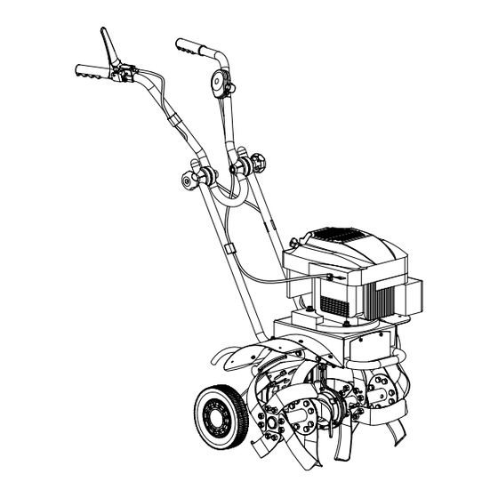
Page 9: Know Your Tiller
Engine oil Engine is shipped from factory without oil. You must add engine oil before starting engine. Add oil according to Engine Manual packed separately with your tiller. KNOW YOUR TILLER Features and Controls Tine Clutch Control Throttle Control Lever Upper Handle Handle Adjustment Knob Lower Handle... -
Page 10: Depth Regulator Rod
Throttle control Wheels bracket release pedal Controls the engine speed and stops the engine. The spring-loaded wheels bracket release pedal locks wheels bracket with depth regulator rod Tine clutch control at different height and distance from the tines. Pushing down to engage tines into forward. Releasing returns machine to neutral. - Page 11 Depth regulator rod Serves a dual purpose. It regulates the tilling depth and helps the operator control the direction and speed of the tiller. Unfold the wheels bracket to raise the wheels to one of the high positions. Set the depth regulator rod with curve down to the rear of the unit.
-
Page 12: Tiller Operation
1. Move throttle lever to “FAST” position. Tiller Operation 2. Hold the start handle firmly and pull rope out Adding fuel a short distance, until you feel some resistance. Then pull the rope smoothly and briskly, and Fill the fuel tank as instructed in the separate allow rope to return gently. -
Page 13: Maintenance
Tilling Cleaning tine area Clean the tiller underside of the tine shield after Tilling is digging in, turning over and breaking up each use. The dirt washes off tines easier if rinsed garden soil and prepare a seedbed for planting. Best tilling depth is 100mm (4”) to 150mm (6”). -
Page 14: Mowerland Tiller
3. While the engine is still warm, drain the oil from the engine. Refill with fresh oil of the grade recommended in the Engine Manual. 4. Allow the engine to cool. Remove the spark plug and put 30 ml (1 oz.) of high quality motor oil into the cylinder. -
Page 15: Trouble Shooting
TROUBLE SHOOTING Cause Remedy Problem 1. Attach spark plug wire securely to spark plug. 1. Spark plug wire disconnected. 2. Fill with clean, fresh gasoline. 2. Out of fuel or stale fuel. 3. Move throttle control lever to start 3. Throttle control lever not in correct position. -
Page 16: Parts Schedule
PARTS SCHEDULE Spares and Helpline 01793 333220 Mowerland Tiller... -
Page 17: Ec Declaration Of Conformity
Directives: - Machinery Directive 98/37/EC Handy hereby declares that the product Machine type: Mowerland Tiller Machine model: MLTILL5 Conforms to the main safety requirements of the EC Directives listed above. This conformity is based on the following standards and normative documents:...
Need help?
Do you have a question about the MLTILL5 and is the answer not in the manual?
Questions and answers