Advertisement
Quick Links
Operator's Manual
18.0-Volt Lithium-Ion Impact Wrench
241-0424
IMPORTANT :
WARNING! To reduce the risk of injury, user must read instruction manual.
Safety symbols in this manual are used to flag possible dangers. The safety
symbols and their explanations require the operator's full understanding. The
safety warnings do not, by themselves, eliminate any danger, and they are not
a substitute for proper accident prevention measures.
This Safety Alert Symbol indicates caution, warning, or danger. Failure to
obey a safety warning can result in serious injury to yourself or others. To reduce
the risk of injury, fire, or electric shock, always follow the safety precautions.
CHARGE BATTERY
BEFORE FIRST USE
Advertisement

Related Manuals for Master-force 241-0424

Summary of Contents for Master-force 241-0424
- Page 1 Operator’s Manual 18.0-Volt Lithium-Ion Impact Wrench 241-0424 CHARGE BATTERY BEFORE FIRST USE IMPORTANT : WARNING! To reduce the risk of injury, user must read instruction manual. Safety symbols in this manual are used to flag possible dangers. The safety symbols and their explanations require the operator’s full understanding. The safety warnings do not, by themselves, eliminate any danger, and they are not a substitute for proper accident prevention measures.
-
Page 2: Table Of Contents
TABLE OF CONTENTS Safety Symbols ....................Page 3 Safety Instructions..................Page 5 Description ...................... Page 9 Assembly ......................Page 10 Operation ......................Page 11 Maintenance....................Page 14 Troubleshooting ....................Page 14 Warranty ......................Page 15 INTRODUCTION SAVE THESE INSTRUCTIONS! This cordless Impact Wrench has many features for making its use more pleasant and enjoyable. -
Page 3: Safety Symbols
SAFETY SYMBOLS The purpose of safety symbols is to attract your attention to possible dangers. The safety symbols and the explanations with them deserve your careful attention and understanding. The symbol warnings do not, by themselves, eliminate any danger. The instructions and warnings they give are no substitutes for proper accident prevention measures. - Page 4 SAVE THESE INSTRUCTIONS Some of these following symbols may be used on this tool. Please study them and learn their meaning. Proper interpretation of these symbols will allow you to operate the tool better and safer. Volts Voltage Amperes Current Hertz Frequency (cycles per second) Watt...
-
Page 5: Safety Instructions
SAFETY INSTRUCTIONS GENRAL SAFETY RULES WARNING! Read all safety warnings and instructions. Failure to follow the warnings and instructions may result in electric shock, fire and / or serious injury. Save all warnings and instructions for future reference. The term power tool in the warnings refers to your mains-operated (corded) power tool or battery-operated (cordless) power tool. - Page 6 PERSONAL SAFETY Stay alert, watch what you are doing and use common sense when operating a power tool. Do not use tool while tired or under the influence of drugs, alcohol, or medication. A moment of inattention while operating power tools may result in serious personal injury. Use personal protective equipment.
- Page 7 keep cutting tools sharp and clean. Properly maintained cutting tools with sharp cutting edges are less likely to bind and are easier to control. Use the power tool, accessories and tool bits etc., in accordance with these instructions, taking into account the working conditions and the work to be performed.
- Page 8 Do not drill, fasten or break into existing walls or other blind areas where electrical wiring may exist. If this situation is unavoidable, disconnect all fuses or circuit breakers feeding this worksite. Always wear safety goggles or eye protection when using this tool. Bit, sockets and tools get hot during operation.
-
Page 9: Description
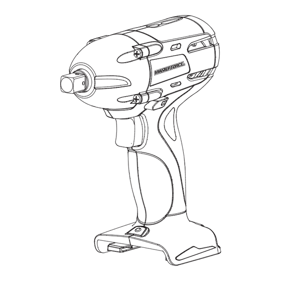
DESCRIPTION kNOW YOUR IMPACT WRENCH (Fig.1) Fig. 1 Vents 1/2” square driver Direction of Rotation seletor Variable Speed Trigger Switch LED Worklight PRODUCT SPECIFICATION Motor 18 Volt DC Switch VSR (Variable Speed Reversible) No Load Speed 0-2500 RPM Impacts per minute 0-3200 BPM Max Torque 1400 in.lbs (with 252-8032 battery pack) -
Page 10: Assembly
FORWARD/REVERSE/CENTER LOCk The direction-of-rotation selector located above the trigger switch changes the direction of bit rotation. Setting the trigger switch in the OFF (center lock) position helps to reduce the possibility of accidental starting. LED WORk LIGHT Pressing the trigger switch illuminates the LED worklight, located on the base of the Impact wrench. -
Page 11: Operation
OPERATION TO ATTACH BATTERY PACk (Fig. 2) Fig. 2 1. Lock the trigger switch on the impact wrench by placing the direction of rotation (forward/ reverse/ center lock) selector in center position. 2. Align the raised rib on the battery pack with the grooves of the wrench, and then attach the battery pack to the wrench. - Page 12 DIRECTION-OF-ROTATION SELECTOR (FORWARD/REVERSE/CENTER LOCk) (Fig. 3b) The direction of bit rotation is reversible Fig. 3b and is controlled by a selector located above the trigger switch. With the Impact Wrench held in normal operating position: 1. Position the direction-of-rotation selector to the left of the tool for forward rotation.
- Page 13 WARNING! Only use sockets de- Fig. 6 signed for impact wrenches. Sockets not designed for impact wrenches could break and result in user injury. Inspect sockets prior to use to ensure that they have no cracks or other vis- ible damage. INSTALLING BITS (Fig.6) 1.
-
Page 14: Maintenance
2. Medium cases: Joining metal to metal with a spring ring washer, disk spring washer, stud bolts or bolts/nuts with conical seats. 3. Soft cases: Joining metal to wood or insulation material. In examples 2 and 3, above, , the maximum tightening torque is less than for hard cases (example 1). -
Page 15: Warranty
WARRANTY If, during normal use, this MASTERFORCE power tool breaks or fails due to a defect in material or workmanship within three years from the date of original purchase, simply bring this tool and its sales receipt back to your nearest Menards retail store for a free equivalent replacement within those three years.
Need help?
Do you have a question about the 241-0424 and is the answer not in the manual?
Questions and answers