Table of Contents
Advertisement
Quick Links
Advertisement
Table of Contents

Summary of Contents for Newport 841-P-USB
- Page 1 Virtual Optical Power Meter 841-P-USB User’s Manual...
- Page 3 INDIRECT, SPECIAL, OR CONSEQUENTIAL DAMAGES RESULTING FROM THE PURCHASE OR USE OF ITS PRODUCTS. First printing 2004 © 2004 by Newport Corporation, Irvine, CA. All rights reserved. No part of this manual may be reproduced or copied without the prior written approval of Newport Corporation.
-
Page 4: Declaration Of Conformity
Declaration of Conformity We declare that the accompanying product, the model 841-P-USB, identified with mark, meets the intent of the Electromagnetic Compatibility Directive, 2004/108/EC. Manufacturer’s Name: Newport Corporation Manufacturer’s Address: 1791 Deere Avenue Irvine, CA 92606 USA Type of Equipment: Laser Power/Energy Meter Model No.:... -
Page 5: Technical Support Contacts
Return the product to Newport Corporation, freight prepaid, clearly marked with the RMA# and we will either repair or replace it at our discretion. Newport is not responsible for damage occurring in transit and is not obligated to accept products returned without an RMA#. -
Page 6: Safety Information
Safety Information Do not use the 841-P-USB if the device or the detector looks damaged, or if you suspect that the 841-P-USB is not operating properly. Appropriate installation must be done for water-cooled and fan-cooled detectors. Refer to the specific instructions for more information. The user must wait for a while before handling these detectors after power is applied. -
Page 7: Waste Electrical And Electronic Equipment (Weee)
For information about where the user can drop off the waste equipment for recycling, please contact your local Newport Corporation representative. -
Page 8: Table Of Contents
Table of Contents Warranty Technical Support Contacts Safety Information Waste Electrical and Electronic Equipment (WEEE) ....v General Information Introduction ...................1 Unpacking..................1 Specifications ................2 Interfaces ..................3 System Operation ... - Page 9 2.3.3.2 Zero Offset .............19 2.3.3.3 Acquire Data ............19 2.3.3.4 Statistics ..............19 2.3.3.5 Send Serial Command..........19 2.3.4 Help - About ..............19 2.3.5 Shortcut buttons...............20 Command Reference USB Installation and Upgrades ...
-
Page 11: General Information
1 General Information 1.1 Introduction To obtain the full performance from the 841-P-USB, we recommend that you read this manual carefully. The 841-P-USB is a microprocessor-based power meter that uses the latest technology to provide a multitude of options in a user-friendly environment. -
Page 12: Specifications
1.3 Specifications The following specifications are based on a one-year calibration cycle, an operating temperature of 18ºC to 28ºC (64ºF to 82ºF) and a relative humidity not exceeding 80%. Power Specifications Power Range 1 nW to 10 kW Physical Scale 2 V, 15 mV Virtual Power Scales 3 nW, 10 nW, 30 nW, 100 nW, 300 nW, 1 µW, 3 µW, 10 µW, 30 µW, 100 µW,... -
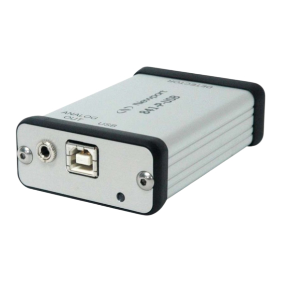
Page 13: Interfaces
1. USB Interface Connector This interface allows remote control and data transfers between the 841-P-USB and a computer that has a USB communication port. 2. Analog Output The analog output is a voltage that can be used to monitor average power or energy by using external equipment such as an oscilloscope, a chart recorder, a computer with an analog interface, a voltmeter, etc. - Page 14 1.025 V corresponds to 5 Watts. Specifications of the analog output: Maximum output voltage: 2.05 V 274 Output impedance: Connector type: Female 1/8” jack 3. Detector Input Connector The 841-P-USB uses a DB15 female connector to mate with the detector heads.
-
Page 15: System Operation
To start, you must tell the 841-P-USB software which port the 841-P-USB will use. To link the 841-P-USB to the COM port, click Ctrl / Communication / Connect. A dialog box appears so that you can select the appropriate serial port (COM 1, COM 2, etc.). - Page 16 818P-series High Power Detector, proceed with step 8. 8- Block off laser radiation to the detector. The power read by the 841-P-USB when no laser beam is incident on the detector may not be exactly zero. This is due to the fact that the detector is not thermally stabilized OR there is a heat source in the field of view of the detector when you turned on the 841-P-USB.
-
Page 17: Top Level Menu Structure
2.3 Top Level Menu Structure This section describes in detail the first group of menu functions essential to the 841-P-USB operation. Refer to Figure 2-1 for a schematic view of the menu structure. The menus differ depending on the type of detector that is currently being used. -
Page 18: Display Menu
2.3.1 Display Menu The 841-P-USB Display menu includes two options that allow you to send serial commands and check the status of the 841-P-USB (see Figure 2-1). You can switch from one option to the other without interfering with the measurement taking process. -
Page 19: Status
the best possible scale, but will oscillate with large variations. Use a fixed scale in this case. 2.3.1.3 Status Figure 2.4 Status window example The Status window displays the detector name and various settings. 2.3.1.4 Statistics Figure 2.5 Statistics in power and energy mode... -
Page 20: Settings Menu
The statistics window displays the current statistics. See section 2.3.2.2 to set the data sampling parameters and to start and stop the statistics. 2.3.2 Settings Menu Options in the Settings menu define user-adjustable acquisition parameters. All correction factors that will affect the reading can be easily programmed. That could be for a beam sampler, attenuator, or other optics that require you to multiply and/or add offsets to the detector reading. -
Page 21: Data Sampling Settings
You can set the 841-P-USB either to calculate the statistics for a single sample and stop or to repeat continuously. Take data for a few seconds or a few weeks. You have the flexibility to handle any application, from analyzing a single short pulse with high resolution to sampling performance over a period of months. - Page 22 To Activate the Statistics, select Statistics from the Ctrl menu, and then select Start in the submenu. Statistics are stopped as a default. The 841-P-USB starts compiling statistics on your measurements as soon as the Statistics mode is activated. Select Stop in the same submenu to turn the Statistics mode off.
- Page 23 The key points to remember are: Sample Rate Measurement frequency e.g. 10 points/second Sample Period Controls the amount of data e.g. 5 minute or 1 day for which the statistics are averages computed Total Duration Controls how long the 841-P- e.g.
-
Page 24: Corrections
[for example, report statistics for 24 hours]. Often the total duration and sample period will be the same. The 841-P-USB automatically clears and recalculates the statistics at the end of each sample period unless you manually stop it. -
Page 25: Power Unit
Multiplier back reflector of a laser (giving 1/1000 #1 and enter 1000 in the dialog box. The 841-P-USB will display the laser’s actual power rather than the measured 0.1% sample on the main display. When a correction factor is active the “Head” value will be different from the displayed measurement. -
Page 26: Trig Level
To change the Trigger Level value, access the dialog box by selecting Trig Level from the Settings menu and enter the desired number in absolute value. The 841-P-USB will not detect pulses with a value under the Trig level. The value of the Trigger level is shown in the status menu confirming that the Trigger level is activated to a specific user level. -
Page 27: Anticipation
The Set Max Analog Out Range setting allows you to choose the maximum voltage that will come from the 841-P-USB. The range of the output is 0 to 2.05 volts. If the user selects 10 Watts as the maximum output range and if the 841-P-USB measures 5 Watts, the analog out is 1.025 volts. -
Page 28: Analog Out Delay
2.3.2.12 Save and Load User Settings The 841-P-USB can remember and recall any number of settings. You can share the 841-P-USB without the hassle of having to re-enter your settings. As an alternative, you can program it so that you can easily switch between different measurement applications without having to re-enter your settings. -
Page 29: Communication
These two items are helpful to check the software version (About Application) and the embedded firmware version (About Device). If you should need help or additional information on the 841-P-USB or any Newport products, do not hesitate to contact us. We will be glad to help you. -
Page 30: Shortcut Buttons
Shortcut buttons To access certain features with a single click instead of having to enter the menus, the 841-P-USB software has 8 shortcut buttons on its main window. From left to right, those buttons access: Ctrl - Zero Offset, Display -... - Page 31 *CFF Turns the power correction OFF “ACK\r\r\n” *AOB Modifies the analog output voltage value (*AOB + 8 “ACK\r\r\n” characters) Example : *AOB1.00E+01 The maximum value of the analog display (2.05 volts) is 10 watts *AOD Sets an analog output delay from 1s to 7s for a return to 0V “ACK\r\r\n”...
- Page 32 Returns more information about current status “Version\t3\tName *F02 \tUP55N-400W- H9\tWavelength All field are separate by a TAB character “\t” \t1064\tTrig Level\t2.500000e- 01\tMax Analog Output \t2.047500e+00\tMode \t0\tOffset\t0\tMUL\t1.0 0000e+00\tOFF\t0.00 0000e+00\tPWCStatu s\t65536\tMinScale\t2 4\tLinearCorr\t1\tAntici pation\t1\tAttenuator \t0” *MUL Modifies the multiplication factor (+ 8 characters) “ACK\r\r\n”...
- Page 33 841-P-USB Error Messages Bad Command Energy Mode is not available The selected wavelength correction factor is not valid The connector is not connected Attenuator not available Communication Settings Bits per second 57600 Data bits Parity None Stop bits Flow control...
-
Page 34: Usb Installation And Upgrades
841-P-USB functions using the USB port power only. Installation for Windows™: Plug the 841-P-USB into a USB port on the PC. If the PC supports USB 1.1, Windows detects the new device and prompts you for the software drivers. A window will open that says Found New Hardware –... -
Page 35: Verify Com Port
Keep up-to-date with the latest version of the 841-P-USB software including new features and options. As new and improved versions of the device's firmware are created, it is in your best interest to update your 841-P-USB. The latest device firmware can be downloaded from the Newport website. -
Page 36: Service Information
2. Instrument serial number (on rear panel) 3. Description of the problem. If the instrument is to be returned to Newport Corporation, you will be given a Return Number, which you should reference in your shipping documents. Please fill out a copy of the service form, located on the following page, and have the information ready when contacting Newport Corporation. -
Page 37: Appendix B
Appendix B 6.1.1.1 Recycling and separation procedure. This section is used by the recycling center when the monitor reaches its end of life. Breaking the calibration seal or opening the monitor will void the solo warranty. The complete Monitor contains 1 Monitor 1 USB cable. -
Page 38: Dismantling Procedure
6.1.1.3 Dismantling procedure: Opening the monitor: Aluminium Enclosure Remove screws Remove Plastic Protectors Remove Screws Electronic PCB inside... - Page 39 Service Form Newport Corporation U.S.A. Office: 800-222-6440 FAX: 949/253-1479 Name_________________________________ Return Authorization # _________________________ (Please obtain RA# prior to return of item) Company ___________________________________________________________________________ Address ______________________________ Date _______________________________________ Country _______________________________ Phone Number _______________________________ P.O. Number ___________________________ FAX Number_________________________________ Item(s) Being Returned:...
- Page 40 Notes:______________________________________________________________________________ ___________________________________________________________________________________ ___________________________________________________________________________________ ___________________________________________________________________________________ ___________________________________________________________________________________ ___________________________________________________________________________________ ___________________________________________________________________________________ ___________________________________________________________________________________ ___________________________________________________________________________________ ___________________________________________________________________________________ ___________________________________________________________________________________ ___________________________________________________________________________________ ___________________________________________________________________________________ ___________________________________________________________________________________ ___________________________________________________________________________________ ___________________________________________________________________________________ ___________________________________________________________________________________ ___________________________________________________________________________________ ___________________________________________________________________________________ ___________________________________________________________________________________ ___________________________________________________________________________________ ___________________________________________________________________________________ ___________________________________________________________________________________ ___________________________________________________________________________________ ___________________________________________________________________________________ ___________________________________________________________________________________ ___________________________________________________________________________________ ___________________________________________________________________________________ ___________________________________________________________________________________ ___________________________________________________________________________________ ___________________________________________________________________________________ ___________________________________________________________________________________ ___________________________________________________________________________________ ___________________________________________________________________________________ ___________________________________________________________________________________ ___________________________________________________________________________________ Internal #200708 Rev. K...
- Page 41 Newport Corporation, Irvine, California; Evry and Beaune-La-Rolande, France have all been certified compliant with ISO 9001 by the British Standards Institution. Mountain View, California is DNV certified.
Need help?
Do you have a question about the 841-P-USB and is the answer not in the manual?
Questions and answers