North Star NSRO42C4 Installation And Operation Manual
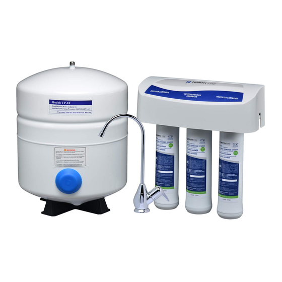
Reverse osmosis drinking water system
Hide thumbs
Also See for NSRO42C4:
- Installation and operation manual (28 pages) ,
- Installation and operation manual (28 pages)
Table of Contents
Advertisement
NSRO42C4
How to Install, operate and
maintain your Reverse Osmosis
Drinking Water System
If you have any questions or concerns when
installing, operating or maintaining your reverse
osmosis system, call our toll free number:
1-800-972-0135
Monday- Friday, 7 AM - 6 PM CST
(in Canada please call
www.northstarconditioning.com
or visit
When you call, please be prepared to provide
the model, date code and serial number of your
product, found on the rating decal, located
inside the cover.
System tested and certified by NSF International
against NSF/ANSI Standards 42 & 58.
See performance data sheet for details.
Designed, Engineered &
Assembled in the U.S.A.
1-800-796-6784
)
Manufactured and warranted by
Ecodyne Water Systems LLC
1890 Woodlane Drive
Woodbury, MN 55125
7313242 (Rev. M 7/1/13)
Advertisement
Table of Contents

Related Manuals for North Star NSRO42C4


Summary of Contents for North Star NSRO42C4
- Page 1 System tested and certified by NSF International against NSF/ANSI Standards 42 & 58. See performance data sheet for details. Manufactured and warranted by Ecodyne Water Systems LLC Designed, Engineered & 1890 Woodlane Drive Assembled in the U.S.A. Woodbury, MN 55125...
-
Page 2: Table Of Contents
TABLE OF CONTENTS Page Warranty ................. . 3 Specifications &... -
Page 3: Warranty
Warranty ONE YEAR LIMITED WARRANTY ON REVERSE OSMOSIS DRINKING WATER SYSTEM (Except filter cartridges and R.O. membrane) Warrantor: North Star Water Conditioning, 1890 Woodlane Drive, Woodbury, MN 55125 Warrantor guarantees, to the original owner, that the Reverse Osmosis Drinking Water System, when installed and maintained in accordance with the instructions, will be free from defects in materials and workmanship for a period of one (1) year from the date of purchase. -
Page 4: Specifications & Dimensions
Specifications & Dimensions Supply water pressure limits ..........40-100 psi (280-689 kPa) Supply water temperature limits . -
Page 5: Unpack And Check Shipment
Unpack and Check Your Carton INSPECT SHIPMENT NOTE: Codes in the state of Massachusetts require installation by a licensed plumber and do not per- Your Reverse Osmosis Drinking Water System is mit the use of saddle valves. shipped complete in one carton. Remove all items from If you live in the state of Massachusetts, review your shipping carton. -
Page 6: Plan Your Installation
Plan Your Installation PLAN YOUR INSTALLATION TOOLS NEEDED Read through the entire manual before beginning your installation. Follow all steps exactly. Reading this manual will also help you get all the benefits from your system. Your Reverse Osmosis Drinking Water System can be installed under a sink or in a remote location. - Page 7 Plan Your Installation All install parts included in package. Drain Adapter for Reverse Tee Feed Osmosis Adaptor Waste Water Cold Water Supply Reverse COLD Osmosis Assembly Storage Tank Sink Drain P-Trap Shutoff Valve Typical Under Sink Installation FIG. 4 Outside Faucet Outside Faucet (Hard Water) (Hard Water)
-
Page 8: Overview & Site Preparation
Overview and Site Preparation OVERVIEW Read through the entire manual before beginning your installation. There are seven steps to installing your Drinking Water system. They are as follows: STEP A - Install Cold Water Supply fitting STEP B - Install Drain Adapter STEP C - Install Reverse Osmosis Assembly STEP D - Install Storage Tank STEP E - Install Reverse Osmosis Faucet... -
Page 9: Installation Instructions
Step A - Install Supply Water Fitting Check and comply with local plumbing codes as you plan, then install a cold feed (supply) water fitting. Refer to the Specifications page for supply water requirements. The fit- ting must provide a leak-tight connection to the RO 1/4" tub- ing. -
Page 10: Step B - Install Reverse Osmosis Drain
Step B - Install RO Drain Under Sink INTRODUCTION Single trap Double Trap A suitable drain point is needed for the drain water from the Reverse Osmosis Filter. You have two options to choose from: Drain • Install the Drain Adapter included with your unit Adapter See Fig 8, Fig. - Page 11 Step B - Install RO Drain In Remote Location Outside Faucet (Hard Water) Outside Faucet BLUE Tubing (Hard Water) to Reverse Osmosis Faucet Soft, Cold Water Soft, Hot GREEN Tubing Soft water Water to Reverse to Reverse Shutoff Osmosis System Osmosis Valve System...
-
Page 12: Step C - Install Reverse Osmosis Filter Assembly
Step C: Install RO Filter Assembly INSTALL REVERSE OSMOSIS FILTER Hanger ASSEMBLY Washer (2) Screw (2) The Reverse Osmosis Filter Assembly is mounted on hanger washers. See Fig 13. The hanger washers allow you to lift the fil- ter assembly from the washers without any hardware removal. -
Page 13: Step D - Install Storage Tank
Step D - Install Storage Tank The fitting on the supply tank may need to be tightened 7-8 full turns to get a good seal. Do not overtighten. Tubing Connector INSTALL STORAGE TANK Tank Nipple 1. Apply of thread sealing tape (2 wraps clockwise) to the threads on the nipple at the top of the tank. - Page 14 Step E: Install RO Faucet SELECT LOCATION OF REVERSE OSMOSIS FAUCET MOUNTING HOLE You will need to select the location of the Reverse Osmosis Faucet. You have three options to choose from: • Use the existing sink top hole for the spray hose or soap dispenser (Must be 1-1/4”...
-
Page 15: Step E - Install Reverse Osmosis Faucet
Step E: Install RO Faucet (cont.) INSTALL REVERSE OSMOSIS FAUCET 1. Locate and organize your RO faucet install parts. Refer to Fig. 16. 2. Snap the o-ring into the groove on the bottom of the ring and slide the monitor ring onto the faucet stud. The monitor ring LED wire must be routed through the sink or counter- top hole and through the spacer, if used. -
Page 16: Step F - Connect Tubes
Step F - Connect Tubes HOW TO CUT AND CONNECT THE TUBES Push-in Fitting Your Reverse Osmosis system includes push-in fittings Foam Plug for quick tubing connection. Review the following instructions before connecting the tubes in the next step. Failure to follow these instructions may lead to future leaks. - Page 17 Step F - Connect Tubes (cont.) NOTE: Tubing lengths should allow for the removal of the assembly from the hanger washers for servicing. If tubing lengths are shortened for neater appear- ance, it may be necessary to keep the assembly on the hanger washers for service.
-
Page 18: Step G - Sanitize, Pressure Test & Purge System
Step G - Sanitize, Test and Purge System SANITIZE THE SYSTEM Sanitizing is recommended immediately after installa- tion of the Reverse Osmosis system. It’s also recom- mended after servicing inner parts. It is important that the person installing or servicing the system have clean hands while handling inner parts of the system. - Page 19 Step G - Sanitize, Test and Purge System (cont.) PRESSURE TEST THE SYSTEM Reverse Osmosis NOTE: Complete the sanitizing procedures on the Kitchen Faucet preceding page before pressure testing. Faucet To pressure test the system, complete the following steps. 1. Open the water supply valve to the Reverse Osmosis system.
-
Page 20: How Your Reverse Osmosis System Works
How Your RO Water System Works INTRODUCTION: Your Reverse Osmosis (RO) Drinking Water System uses your household water Battery PWA Board pressure to force water through three filters. Minerals and impurities are filtered out. Delicious tasting drink- ing water goes to the storage tank-ready for your use. Minerals and impurities are sent down the drain. - Page 21 How Your RO Water System Works PRODUCT WATER FAUCET Air Gap PRODUCT WATER Gravity Drain DRAIN WATER Drain Flow AUTOMATIC Check Control SHUTOFF Valve WATER GREEN BLUE PRODUCT PREFILTER POSTFITLER WATER STORAGE MEMBRANE YELLOW FIG. 28 Reverse Osmosis Water Flow Schematic Water Flow Description 1.
-
Page 22: Maintenance
Maintenance PREFILTER/POSTFILTER MAINTENANCE NOTE: It is recommended to replace the battery, prefilter and postfilter cartridges at least every 6 months of product water use. Replace more often if Cover they begin to plug with sediment. The prefilter and postfilter are replaceable sediment cartridges with activated carbon in their composition. - Page 23 Maintenance FLOW CONTROL The flow control is required for proper operation of the Flow Control Reverse Osmosis system. See Fig. 30. The flow con- Insert trol, located inside the push-in elbow fitting on the drain Push-in port of the system housing, keeps water flowing through Elbow Fitting the membrane at the required rate.
-
Page 24: Troubleshooting
Troubleshooting Problem: Chlorine taste and/or odor in the RO product water. Cause: The level of chlorine in your water supply Correction: If the water supply contains more than 2.0 ppm of chlorine, addition- exceeds maximum limits, and has al filtering of the water supply to the Reverse Osmosis is needed. destroyed the Reverse Osmosis mem- Contact your local water supplier. - Page 25 Troubleshooting Problem: Water leaking from faucet airgap hole. Cause: Drain side of faucet airgap (3/8” black tub- Correction: Inspect and eliminate restriction or plug. Check that drain line is ing) plugged, restricted or incorrectly con- routed properly. Refer to installation instructions for proper drain nected to drain point.
-
Page 26: Exploded View & Parts List
Exploded View 1/4” red tubing... -
Page 27: Parts List
Parts List Part No. Description Part No. Description Automatic Shutoff Kit (incl. Key No. 3, Rep’l Manifold Assembly – 7333145 7296521 4 of Key No. 2 & 6 of Key No. 1) (includes Key Nos. 1-8 & 11-14) Mounting Hardware Kit Screw (6 req’d) –... - Page 28 - PARTS RETURN TAGS - If you have a defective part or assembly under warranty, please fill in a parts return tag. Cut out the tag and include it with the defective part when you return it to the place where you purchased the unit.
Need help?
Do you have a question about the NSRO42C4 and is the answer not in the manual?
Questions and answers
WATER PRESSURE DECREASES RAPIDLY
A rapid water pressure decrease in the North Star NSRO42C4 Reverse Osmosis system can be caused by the normal operation of the system, where water pressure from the RO faucet is less than a standard faucet. Additionally, slow water flow during system purging or a full storage tank causing the drain flow to stop can also affect pressure.
This answer is automatically generated