Table of Contents
Advertisement
Advertisement
Table of Contents

Related Manuals for Daewoo DWF-270G


Summary of Contents for Daewoo DWF-270G
-
Page 1: Service Manual
SERVICE MANUAL Automatic Washing Machine Model:DWF-270G Caution: In this Manual, some parts can be changed for improving,their performance without notice in the parts list. So, if you need the latest parts information, please refer to the Service Information Center (http://www.weili.com.cn). -
Page 2: Table Of Contents
Contents 1. SPECIFICATIONS........................2 2. STRUCTURE OF THE WASHING MACHINE................3 3. DIRECTIONS FOR INSTALLATION AND USE................4 INSTALLATION OF THE UNDER BASE COVER ..................4 HOW TO INSTALL ON AN INCLINED PLACE .....................4 HOW TO CONNECT THE INLET HOSE ......................5 HOW TO CLEAN ................................. -
Page 3: Specifications
1. SPECIFICATIONS DWF-270G ITEM POWER SOURCE AVAILABLE IN ALL LOCAL AC VOLTAGE AND CYCLE 340W 50Hz POWER CONSUMPTION 340W 60Hz 27.8Kg NON-PUMP MACHINE WEIGHT 28.8Kg PUMP DIMENSION (WXHXD) 545 X 906 X 555 FULL AUTOMATIC 8 COURSE WASHING COURSE (NORMAL,HEAVY,SPEEDY,GENTLE,TUB SELF-CLEAN,... -
Page 4: Structure Of The Washing Machine
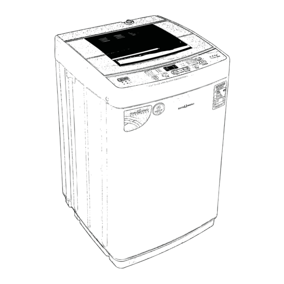
2. STRUCTURE OF THE WASHING MACHINE The parts and features of your washer are illustrated on this page. Become familiar with all parts and features before using your washer. NOTE The drawing in this book may vary from your washer model. They are designed to show the different features ©... -
Page 5: Directions For Installation And Use
3. DIRECTIONS FOR INSTALLATION AND USE INSTALLING PLACE Install the washer on a horizontal solid floor. If the washer is installed on an unsuitable floor, it could make considerable noise and vibration. Never install in these places The place where it would be exposed to direct sunlight. -
Page 6: How To Connect The Inlet Hose
HOW TO CONNECT THE INLET HOSE Confirm the water faucet Water faucet,suitable Water faucet,not suitable Outlet end surface >10mm It is required that the front end shall be longer than 10cm. The outlet end surface of the faucet shall be flat and smooth. If not please file it to avoid leakage. Connection between the water inlet hose jointer and the water faucet 1.Press the lower end of the lock lever and push down the slider. -
Page 7: How To Clean
HOW TO CLEAN CLEANING THE LINT FILTER Pull the Filter frame Turn the lint filter Return the filter as it was, and upward. inside out, wash to insert the filter frame into the the lint off with water. slot. Filter Frame Lint Filter CLEANING THE WATER INLET FILTER Clean the filter when water leaks from the water inlet. -
Page 8: Feature And Technical Explanation
4. FEATURE AND TECHNICAL EXPLANATION FEATURE OF THE WASHING MACHINE The first applying Radical Technology in the world..go beyond washing, sterilize your clothes and deodorize a bad smell. Quiet washing through the innovational low-noise design. The adoption of the water currents to adjust the unbalanced load. Transparency display window. -
Page 9: Automatic Draining Time Adjustment
AUTOMATIC DRAINNING TIME ADJUSTMENT This system adjusts the draining time automatically according to the draining condition. Good draining The washer begins spin process after drainage. Draining Bad draining Draininig time is prolonged. condition No draining Program is stopped and gives the alarm. FUNCTIONAL PRINCIPLE The micom can remember the time from the begining of drain to reset point when the pressure switch reaches to”OFF”point... -
Page 10: Directions For Disassembly And Adjustment
5. DIRECTIONS FOR DISASSEMBLY AND ADJUSTMENT Warning BEFORE ATTEMPTING TO SERVICE OR ADJUST ANY PART OF THE WASHING MACHINE, DISCONNECT THE POWER CORD FROM THE ELECTRIC OUTLET. KEY POINTS IN DISASSEMBLY 1) GENERAL ATTENTION Be sure to pull off the power plug in disassembly or maintenance. Use stipulated crimp terminals in connecting the wires between the conducting wires as far as possible, and fix with suitable tools, and insulate with insulation tape completely. -
Page 11: Gear Mechanism Ass'y Replacement
GEAR MECHANISM ASS’Y REPLACEMENT Raise the control panel seat on the outer cabinet. Loosen the pulsator mounting screw and remove the Loosen four screws mounting outer tub cover and pulsator. remove outer tub cover from the tub ass's. Remove the four screws by screw drive. Remove the tub ass’y. -
Page 12: Drain Motor And Valve Replacement
DRAIN MOTOR AND VALVE REPLACEMENT (NON PUMP MODEL) Lay the front of the washer on the floor. Take out the wire of drain motor from the braket. Loosen two special screw of drain motor. Separate the drain motor from the base. Turn the valve by using screw driver as shown in pic- Remove the valve lid from the valve drain ass’y. -
Page 13: Trouble Shooting Guide
6. TROUBLE SHOOTING GUIDE TEST PROGRAM (TEST WITHOUT WATER) Push and hold the "program" and "cold/warm/hot water" buttons, then push down the "power" button to enter test program. Push the "process", The program will switch as follow: Test A Test B Test C Test name Test content... -
Page 14: Concerning No Rotation In Washing
CONCERNING NO ROTATION IN WASHING Start the test without water .enter no-water washing. Please check the transmission system carefully. Check the action of the motor. Exist Measure the voltage of the two If the motor overheat protector acts. ends of the motor. Not exist Please check the reason. -
Page 15: Concerning No Draining
CONCERNING NO DRAINING Set rinse or spin. Start the machine. Act normally Check the drain system like the drain valve ect. Check if the drain puller acts. Exist Measure the voltage of the two Replace the drain puller. ends of the drain puller Not exist Exist Measure the voltage of the two ends of... -
Page 16: Concerning Too Much Noise In Washing
CONCERNING TOO MUCH NOISE IN WASHING Replace the motor. If the noise of the motor is too much. Fasten the motor. If the motor fastened tightly. Replace the retarder. If the inner gear of the retarder is engaged well. Adjust the belt. If the belt is too tight or loose. -
Page 17: Concerning Time-Out In Brake
CONCERNING TIME-OUT IN BRAKE If the brake moment of the retarder Adjust the brake moment. is smaller than 4N.m If the resetting spring of the retarder Adjust the resetting spring. is too soft If the gap between the connecting arm Adjust the rubber bushing. -
Page 18: Trouble-Shooting Table
TROUBLE-SHOOTING TABLE Phenomenan The reason How to settle Is the drain hose put down? Put down the drain hose. The draining does not work, or the speed of draining is too slow ,The numeral tube Is the drain hose blocked by foreign Open and close the top lid once. -
Page 19: Usage Of The Operation Buttons
7.USAGE OF THE OPERATION BUTTONS Indicator mode and meaning Digital tube The indicator is off,indicating that the program During operating of program,it displays or mode is not selected the remained time(minute) During the preset program,it displays the The indicator is flashing,indicating the running remained reserve time(hour) program In abnormal cases,it displays the symbol... - Page 20 "Power on/off"button “Water temp"button One or more program is available among Push the button once to switch on Push the button once you can select the following:normal,heavy,speedy,gentle the power “cold water”,”warm water” or “hot tub self-clean,air dry,water saving,fine When the power is on,push the water”...
-
Page 21: Circuit Diagram
8. CIRCUIT DIAGRAM circuit diagram Computer sequencer CIRCUIT DIAGRAM... -
Page 22: Pcb Circuit Diagram
PCB circuit diagram CIRCUIT DIAGRAM... -
Page 23: Parts Diagram
9. PARTS DIAGRAM PARTS DIAGRAM... - Page 24 PARTS DIAGRAM...
- Page 25 PARTS DIAGRAM...
- Page 26 PARTS DIAGRAM...
- Page 27 PARTS DIAGRAM...
- Page 28 PARTS DIAGRAM...
- Page 29 PARTS DIAGRAM...
- Page 30 PARTS DIAGRAM...
- Page 31 PARTS DIAGRAM...
Need help?
Do you have a question about the DWF-270G and is the answer not in the manual?
Questions and answers