Sign In
Upload
Download
Table of Contents
Contents
Add to my manuals
Delete from my manuals
Share
URL of this page:
HTML Link:
Bookmark this page
Add
Manual will be automatically added to "My Manuals"
Print this page
×
Bookmark added
×
Added to my manuals
Manuals
Brands
HP Manuals
Laptop
OmniBook 300
Service manual
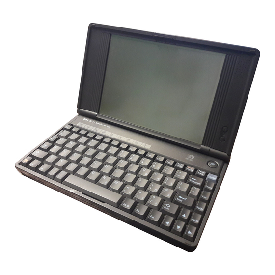
HP OmniBook 300 Service Manual
Hide thumbs
1
2
3
Table Of Contents
4
5
6
7
8
9
10
11
12
13
14
15
16
17
18
19
20
21
22
23
24
25
26
27
28
29
30
31
32
33
34
35
36
37
38
39
40
41
42
43
44
45
46
47
48
49
50
51
52
53
54
55
56
57
58
59
60
61
62
63
64
65
66
67
68
69
70
71
72
73
74
75
76
77
78
79
80
81
82
83
84
85
86
87
page
of
87
Go
/
87
Contents
Table of Contents
Troubleshooting
Bookmarks
Table of Contents
Table of Contents
Table of Figures
Introduction
Product Overview
Product Features
Omnibook 300, 425, and 430
Figure 1 - Omnibook 300, 425, and 430 Features
Omnibook 530
Figure 2 - Omnibook 530 Features
Product Comparisons
Omnibook 530
Product at a Glance
Troubleshooting
Omnibook Self-Test
Loop Back Connectors
Figure 3 - Serial Loop Back Connector
Figure 4 - Parallel Loop Back Connector
Troubleshooting Flowchart
Main Troubleshooting Flowchart
Power Source Problems
Boot-Up Problems
Display Problems
Hard Disk Problems
Memory Problems
Power Management Problems
Pop-Out Mouse Problems
Floppy Drive Problems
Parallel Port Problems
Serial Port Problems
PCMCIA Problems
IR Port Problems
Hardware Repair
Battery (End User Replaceable)
Memory (End User Replaceable)
Figure 5 - Omnibook Memory Modules
Figure 6 - Removing the Memory Module
Hard Disk Drive/Flash Card and System ROM (End User Replaceable)
Figure 7 - Removing Card Slot Tray
Mouse (End User Replaceable)
Figure 8 - Removing the Mouse
Small Parts (End User Replaceable)
Battery Door
Battery Door Latch
Blank Modem Door
Memory Door
I/O Door
Rubber Feet
PCMCIA Card Tray
Display (HP Authorized Service Providers Only)
Figure 9 - Outer Bottom Case Components
Figure 10 - Backplane Standoffs
Figure 11 - Bottom Case Tabs
Figure 12 - Bottom Case Prying Locations
Figure 13 - I/O Port Prying Location
Figure 14 - Disconnecting Display Cable
Figure 15 - Keyboard Flex Cables
Figure 16 - Display Grounding Eyelets
Figure 17 - Display Cable Probe Position
Figure 18 - Reconnecting Display Cable
Figure 19 - I/O Port Eyelets (All Present)
Figure 20 - I/O Port Eyelets (Two Matched Sets)
Figure 21 - I/O Port Eyelets (Only One Matched Set)
Figure 22 - I/O Port Eyelets (no Eyelet in Position One)
Keyboard (HP Authorized Service Providers Only)
Logic PCA Board (HP Authorized Service Providers Only)
Figure 23 - Logic Board PCA Removal
Paw Carrier (Paw Active) (HP Authorized Service Providers Only)
Figure 24 - Paw Carrier Removal
Other Components (HP Authorized Service Providers Only)
Appendix A - Technical and Resource Specifications
Mass Storage Specifications
Card Services and Socket Services Version Matrix
Memory Map
Upper Memory Block Space
DOS Conventional Memory
Appendix B - Power on Self Test Codes
Beep Codes
Display Codes
Appendix C - Password Policy
Advertisement
Quick Links
1
Table of Contents
2
Omnibook 300, 425, and 430
Download this manual
Service Manual
HP OmniBook 300, 425, 430, 530
Table of
Contents
Previous
Page
Next
Page
1
2
3
4
5
Advertisement
Table of Contents
Troubleshooting
Troubleshooting
16
Troubleshooting Flowchart
19
Main Troubleshooting Flowchart
20
Need help?
Do you have a question about the OmniBook 300 and is the answer not in the manual?
Ask a question
Questions and answers
Related Manuals for HP OmniBook 300
Laptop HP OMNIBOOK 3000 User Handbook Manual
Hewlett-packard laptop user manual (59 pages)
Laptop HP OMNIBOOK OmniBook 3000 Evaluator Manual
Corporate evaluator’s guide (108 pages)
Laptop HP OmniBook 2000 User Manual
Hardware diagnostics (44 pages)
Laptop HP OmniBook 3000 Reference Manual
Hp omnibook 3000: reference guide (133 pages)
Laptop HP OMNIBOOK 2100 Service Manual
(107 pages)
Laptop HP OmniBook 3000 - Notebook PC Manual
Hp omnibook 3000 pc corporate evaluator's guide - not orderable (108 pages)
Laptop HP OmniBook 3000 Service Manual
Hp omnibook 3000 (86 pages)
Laptop HP OmniBook 3100 Service Manual
(98 pages)
Laptop HP OmniBook 2100 Service Manual
(20 pages)
Laptop HP OmniBook 2100 - Notebook PC Using Manual
Hp omnibook 2100 - recent hp omnibook information windows 95 & windows nt bios ver 1. xx (9 pages)
Laptop HP OmniBook 2100 User Manual
Hp omnibook 2100: user guide (53 pages)
Laptop HP OmniBook 2100 Supplementary Manual
Operating the hp notebook pc with a windows 2000 upgrade (4 pages)
Laptop HP OmniBook 2100 Reference Manual
Hp omnibook 2100: reference guide (150 pages)
Laptop HP OmniBook 6000 Service Manual
Hewlett-packard laptop pc service manual (96 pages)
Laptop HP 6000 Service Manual
Hp omnibook 6000/6100 (114 pages)
Laptop HP DesignJet 500 Service Manual
Hewlett-packard omnibook service manual (112 pages)
This manual is also suitable for:
Omnibook 425
Omnibook 430
Omnibook 530
Table of Contents
Print
Rename the bookmark
Delete bookmark?
Delete from my manuals?
Login
Sign In
OR
Sign in with Facebook
Sign in with Google
Upload manual
Upload from disk
Upload from URL


Need help?
Do you have a question about the OmniBook 300 and is the answer not in the manual?
Questions and answers