Advertisement
Quick Links
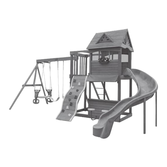
STONEYBROOK LODGE PLAY SYSTEM – F23100
INSTALLATION AND OPERATING INSTRUCTIONS
18' 8" (5.7 m)
10 - 14 Hrs
Two person
assembly
3403100
WARNING
often and give them to any future owner of this play system. Manufacturer contact information provided below.
OBSTACLE FREE SAFETY ZONE - 32'3" x 28' (9.8 x 8.5 m) area requires Protective Surfacing. See page 3.
MAXIMUM VERTICAL FALL HEIGHT - 7'6" ft. (2.3 m)
CAPACITY - 12 Users Maximum, Ages 3 to 10; Weight Limit 110 lbs. (49.9 kg) per child.
RESIDENTIAL HOME USE ONLY. Not intended for public areas such as schools, churches, nurseries,
day cares or parks
Solowave Design
375 Sligo Rd. West, PO Box 10
Mount Forest, ON Canada N0G 2L1
General Inquiries:
8:00am - 4:30pm EST
Toll Free: 1-877-966-3738
support@solowavedesign.com
To reduce the risk of serious injury or death, you must read and
follow these instructions. Keep and refer to these instructions
Table of Contents
Warnings and Safe Play Instructions . . . . . . . . . . pg. 2
Protective Surfacing Guidelines . . . . . . . . . . . . . . pg. 3
Instructions for Proper Maintenance . . . . . . . . . . pg. 4
About Our Wood – Limited Warranty . . . . . . . . . . pg. 5
Keys to Assembly Success . . . . . . . . . . . . . . . . . . pg. 6
Part ID . . . . . . . . . . . . . . . . . . . . . . . . . . . . . . . . . . pg. 7
Installation of I.D./Warning Plaque . . . . . . . . Final Step
Rev 12/29/2010
Advertisement

Related Manuals for Big Backyard F23100


Summary of Contents for Big Backyard F23100
- Page 1 STONEYBROOK LODGE PLAY SYSTEM – F23100 INSTALLATION AND OPERATING INSTRUCTIONS WARNING To reduce the risk of serious injury or death, you must read and follow these instructions. Keep and refer to these instructions often and give them to any future owner of this play system. Manufacturer contact information provided below.
- Page 6 Square Assembly...
- Page 7 Part Identification (Reduced Part Size) A1 - B13 (2) Mid Wall Board 1 x 6 x 48-1/2" Nominal Size Actual Size 1½" x 5 " ⅜ 2" x 6" 3631422 Box 1 " x 3 " ⅜ ⅜ 2" x 4" (1) Sunburst 5/4 x 5 x 13"...
- Page 8 Part Identification (Reduced Part Size) B14 - B30 (2) Lower Diagonal 2 x 3 x 37" Nominal Size Actual Size 3640369 Box 2 1½" x 5 " ⅜ 2" x 6" " x 3 " ⅜ ⅜ 2" x 4" (1) Ladder Bottom 5/4 x 4 x 20"...
- Page 9 Part Identification (Reduced Part Size) C1 - C27 (1) CE Gap Board 1 x 6 x 38-3/4" 3630840 Box 3 (1) Front Beam 2 x 6 x 94" 3631248 Box 3 (1) Back Beam 2 x 6 x 94" 3631249 Box 3 (24) Cedar Roofing 3/8 x 3-1/2 x 47-1/2"...
- Page 10 Hardware Identification (Actual Size) (2) Hex Bolt 1/4 x 2" 9277220 1/4" Lock Washer - 1/4" Flat Washer - 1/4" T-Nut (8) Hex Bolt 1/4 x 2 1/2" 9277222 1/4" Lock Washer - 1/4" Flat Washer - 1/4" T-Nut (12) Hex Bolt 1/4 x 4" 9277240 1/4"...
- Page 11 Hardware Identification (Actual Size) 9277352 (4) Hex Bolt 5/16 x 5 1/2" 2 - 5/16" Flat Washer, 5/16" Lock Nut 9277320 (2) Hex Bolt 5/16 x 2" 2-5/16" Flat Washer, 1- 5/16" Lock Nut 9277230 (4) Hex Bolt 1/4 x 3" 1/4"...
- Page 12 1X 3320188 Rocks (11pk) 3X 9201500 3-Burgundy 4-Green 4-Yellow Spiral Wave Bracket 1X 3200202 Glider Hanger (2pk) 1X 3320356 Big Backyard I.D Plaque w hardware 1X 3200142 -Green 1X 3320190 WW Mount Strap (2pk) 1X 3750100 Stonybrook Lodge Stool Seat Set (2pk)
- Page 13 PRODUCT NUMBER: F23100 CARTON I.D. STAMP: __ __ __ __ __ 14459 ___ (Box 1) CARTON I.D. STAMP: __ __ __ __ __ 14459 ___ (Box 2) CARTON I.D. STAMP: __ __ __ __ __ 14459 ___ (Box 3) CARTON I.D. STAMP: __ __ __ __ __ 14459 ___ (Box 4) CARTON I.D.
- Page 14 Step 1: Attach Wiggle Wall Bottom Board A: Place 2 (B29) Wiggle Joists side by side so they match each other and are 19-7/8” apart from the outside edges. (fig. 1.1) B: Attach (A6) Wiggle Bottom to the bottom of each (B29) Wiggle Joist using 4 (S2) #8 x 1-1/2” Wood Screws. The ends of (A6) Wiggle Bottom are flush to the sides of each (B29) Wiggle Joist and the bottom edge of (A6) Wiggle Bottom is flush to the ends of (B29) Wiggle Joist as shown in (fig.
- Page 15 Step 2: Layout Top of Wiggle Wall and Attach Rocks A: At the top of the (B29) Wiggle Joists place 1 (A5) Wiggle Board C then follow by 1 (A3) Wiggle Board A, 2 (A4) Wiggle Board B, 1 (A3) Wiggle Board A and then 1 (A4) Wiggle Board B as shown in (fig. 2.2). Rock holes should be staggered.
- Page 16 Step 3: Attach Top Wall Caps A: Attach 1 - Wiggle Wall Cap Left to the left side of the Wiggle Boards as shown in fig. 3.1. B: The tab inside the cap should fit between the Wiggle Boards so a slight gap will form. (fig. 3.2) C: Make sure the cap end is flush to the top of (B29) Wiggle Joist and then attach Wiggle Wall Cap Left to the (B29) Wiggle Joist with 5 (S5) #8 x 1/2”...
- Page 17 Step 4: Fasten Wiggle Boards A: Make sure distance from outside of each (B29) Wiggle Joists measures 19-7/8” (fig. 4.1) and then attach (A5) Wiggle Board C to each (B29) Wiggle Joist using 4 (S2) #8 x 1-1/2” Wood Screws. (fig. 4.2) B: Reconfirm the distance from outside of each (B29) Wiggle Joist measures 19-7/8”...
- Page 18 Step 5: Layout Bottom of Wiggle Wall and Attach Rocks A: Starting directly below the last (A4) Wiggle Board B, place another (A4), followed by 1 (A3) Wiggle Board A, 2 (A4) Wiggle Board B, 1 (A3) Wiggle Board A and then the last (A4) Wiggle Board B. Rock holes should be staggered as shown in fig.
- Page 19 Step 6: Attach Bottom Wall Caps & Remaining Wiggle Boards A: Attach 1 - Wiggle Wall Cap Left to the left side of the Wiggle Boards as shown in fig. 6.1. B: The tab inside the cap should fit between the Wiggle Boards so a slight gap will form. (fig. 6.2) C: Make sure the cap end is tight to the bottom of the previously attached Wiggle Wall Cap - Left and then attach the bottom Wiggle Wall Cap - Left to the (B29) Wiggle Joists with 5 (S5) #8 x 1/2”...
- Page 20 Step 7: Dormer Assembly Fig. 7.2 Fig. 7.3 Fig. 7.1 Wall angle bracket Dormer Roof Dormer Roof with Hardware Set - Right Set - Left A: Attach 1 Dormer Roof Set Right to 1 Dormer Roof Set Left with 1 Wall Angle Bracket with the hardware provided at the inside peak as shown in (fig.
- Page 21 Step 8: Swing Beam Assembly Fig. 8.2 Hex Bolt Assembly Lock T- Nut Warning: For your childs safety, Washer orientate the swing hangers as shown to ensure your swing will have proper swing motion when Flat He x Washer Bolt installed.
- Page 22 Step 9: Swing End Assembly Hex Bolt Assembly Lock T- Nut Washer Flat He x Washer Bolt A: Attach 2 (C27) SW Posts to (C26) SW Upright using 2 (G4) 5/16 x 4” Hex Bolts (with lock washer, flat washer and t-nut).
- Page 23 (H8) 1/4 x 4-1/4” Hex Bolt (with lock washer, flat washer and t-nut). Hex Bolt is to be installed on the (C3) Back Beam side and t-nut is on the (C2) Front Beam. (fig. 10.1 & 10.2) B: Place the Big Backyard Plaque over the t-nut on the (C2) Front beam and attach using the hardware provided with the plaque. (fig. 10.2)
- Page 24 Step 11: Access Ladder Assembly Fig. 11.1 A: Insert 4 (A15) 1-1/8 x 18-5/8” Dowels into both (B27) Left Access and (B28) Right Access as shown in fig. 11.1. Fig. 11.2 Make sure shoulder Make sure shoulder Make sure shoulder is against Post before Make sure shoulder drilling pilot holes...
- Page 25 Step 12: Post Assembly A: Place 1 (C13) Post beside 1 (C14) Lower Post making sure the 3 holes in (C13) Post are at the top of the boards and facing the front as shown in fig. 12.1. B: To align holes properly, insert a bolt through the bottom holes of (C13) Post and (C14) Lower Post as shown in fig.
- Page 26 Step 13: Swing Wall Assembly Hex Bolt Assembly Lock T- Nut Washer Flat He x Washer Bolt A: Attach (B18) Ground SW Side to 2 Post Assemblies with 4 (H4) 1/4 x 4” Hex Bolts (with lock washer, flat washer and t-nut) making sure 1 bolt is installed in each (C13) Post and (C14) Lower Post as shown in fig.
- Page 27 Step 13: Swing Wall Assembly cont. Predrill Pilot Holes for Lag Screw Hex Bolt Assembly Note: Pre-drill all holes using a Lock Predrill 1/8” T- Nut Washer Screw pilot hole 1/8” drill bit before installing the lag screws. Flat Use factory drilled Flat He x Washer...
- Page 28 Step 14: Slide Wall Assembly Hex Bolt Assembly Lock T- Nut Washer Flat He x Washer Bolt A: Attach (B17) Ground SL Side to the remaining 2 Post Assemblies with 4 (H4) 1/4 x 4” Hex Bolts (with lock washer, flat washer and t-nut) making sure 1 bolt is installed in each (C13) Post and (C14) Lower Post as shown in fig.
- Page 29 Step 15: Front and Back Frame Assembly Hex Bolt Assembly Lock T- Nut Washer Flat He x Washer Bolt Keep all bolts in this step loose until a later step. A: Attach 1 (B20) Floor Front Back to the inside of each Post Assembly on both the Swing Wall and Slide Wall Sides using 1 (H11) 1/4 x 2-3/4”...
- Page 30 Step 16: Attach Mid Posts Hex Bolt Assembly Lock T- Nut Washer Flat He x Washer Bolt A: On the front of the assembly measure 39-3/4” from the inside of a Post Assembly on the Slide Wall side (fig. 16.2) and attach 1 (C15) Mid Post to the (B20) Floor Front Back with 1 (H11) 1/4 x 2-3/4” Hex Bolt (with lock washer, flat washer and t-nut).
- Page 31 Step 17: Floor Frame Assembly 2" Hex Bolt Assembly Lock T- Nut Washer Flat He x Washer Bolt A: Remove the bottom bolt in (C24) Wall Mount. Do not discard this bolt you will re-install it after the (B19) Floor Joist is attached.
- Page 32 Step 18: Attach Floor Boards A: In between both (B2) CE Gap Board and (C1) CE Gap Board place 20 (B2) CE Gap Boards making sure they are evenly spaced. Attach to (B19) Floor Joist and both (B20) Floor Front Back using 5 (S2) #8 x 1-1/2” Wood Screws per board.
- Page 33 Step 19: Top Frame Assembly Hex Bolt Assembly Lock T- Nut Washer Flat He x Washer Bolt A: Attach 1 (C18) Top Back Front to each (C13) Post on the front of the assembly with 2 (H3) 1/4 x 2-1/2” Hex Bolts (with lock washer, flat washer and t-nut) per side.
- Page 34 Step 20: Attach SL Roof Support A: On the Slide Wall side attach 1 (C20) SL Roof Support to each (C13) Post with 7 (S2) #8 x 1-1/2” Wood Screws per board. The (C20) SL Roof Support should be tight against the gap boards and flush to the outside edge of (C13) Posts.
- Page 35 Step 21: Attach Floor Gap A: On the Slide Wall Side in between (C15) Mid Post and (C13) Post, both front and back side, attach 1 (C21) Floor Gap to each (B20) Floor Front Back with 4 (S3) #8 x 2-1/2: Wood Screws per board. (fig. 21.1). Make sure both (C21) Floor Gaps are flush to the top of the floor boards.
- Page 36 Step 22: Window Wall Assembly These directions are for both the front and back of the assembly. Fig. 22.1 A: On the Slide Wall side on both (C13) Posts attach 1 (B3) Wall Trim per post, tight to the bottom of (C18) Top Back Front and flush to the outside edge of (C13) Post with 4 (S2) #8 x 1-1/2”...
- Page 37 Step 23: Attach Window Mesh and Window Sill These directions are for both the front and back of the assembly. A: From the inside of the assembly, centre 1 Window Mesh against (C18) Top Back Front making sure it covers the opening between (C18) Top Back Front and (B9) Siding and there is an overhang on each side.
- Page 38 2" 8" 8" 8" 8" 2" Step 23: Attach Window Mesh and Window Sill cont. These directions are for both the front and back of the assembly. B: Loosen bolts in (C18) Top Front Back, tuck in the Window Mesh and then retighten bolts. (fig. 23.2) C: On the outside of the assembly, tight to the top of (B9) Siding, attach 1 (C19) Window Sill to (C13) Post and (C15) Mid Post with 4 (S2) #8 x 1-1/2”...
- Page 39 Step 24: Attach Window Braces and Divider These directions are for both the front and back of the assembly. A: Tight to the top of (C18) Top Back Front, attach 1 (C19) Window Sill, 1-3/8” from outside edge of (C17) Roof Block, to (C16) Mid Roof Block and (C17) Roof Block using 4 (S2) #8 x 1-1/2”...
- Page 40 Step 24: Attch Window Braces and Divider cont. These directions are for both the front and back of the assembly. C: From the outside of the assembly, attach (B9) Siding to each (B22) Window Brace and to (C21) Floor Gap with 2 (S0) #8 x 7/8”...
- Page 41 Step 25: Attach Pickets A: Between (C13) Posts and (C24) Wall Mount on the Swing Wall side attach 3 (B24) Pickets, with bevelled edges to the top and facing out, to (C10) SW Top and (C11) SW Floor with 2 (S15) #8 x 1-3/4” Wood Screws per board.
- Page 42 Step 26: Attach Roof Side Hex Bolt Assembly Lock T- Nut Washer Flat He x Washer Bolt A: To each (C17) Roof Block on the Slide Wall side attach 1 (A12) Roof Side with 2 (H6) 1/4 x 4-3/4” Hex Bolts (with lock washer, flat washer and t-nut).
- Page 43 Step 27: Roof Frame Assembly A: Connect 2 (B25) Roof Supports together at the peak using 1 (S4) #8 x 3” Wood Screw. Repeat this to create 2 Roof Support Assemblies. Make sure the supports are tight to each other. (fig. 27.1) B: Connect 2 (B26) Roof Joists together at the peak using 1 (S4) #8 x 3”...
- Page 44 Step 28: Attach Roof End & Roofing A: Attach 10 more (C4) Cedar Roofings per side to both Roof Support Assemblies and Roof Joist Assembly with 3 (S0) #8 x 7/8” Truss Screws per (C4) Cedar Roofing. Be sure that one (C4) Cedar Roofing overlaps the other, leaving no gaps.
- Page 45 Step 29: Attach Roof to Fort Hex Bolt Assembly Lock T- Nut Washer Flat He x Washer Bolt A: With at least 2 helpers lift roof onto fort at Slide Wall side of the fort. The Roof Support Assembly without the (C23) Roof Ends should rest flush to the bottom of (A12) Roof Side.
- Page 46 Step 30: Attach Gable Boards and Tarp A: From the inside of the Roof Assembly, on the Mid Post side, attach (C6) Gable Block B to both (B25) Roof Supports with 4 (S2) #8 x 1-1/2” Wood Screws. This board should fit as tight to the peak as possible. (fig. 30.1 &...
- Page 47 Step 30: Attach Gable Boards and Tarp cont. C: With the assistance from a helper, from the inside of the Roof Assembly attach (B6) Centre Gable Board to the peak of the Roof Support Assembly; centre on (A2) Sunburst and (A12) Roof Side with 3 (S2) #8 x 1-1/2”...
- Page 48 Step 31: Mid Wall Assembly A: Attach 1 (C22) Wall Brace flush to edge of each (C15) Mid Post with 2 (S4) #8 x 3” Wood Screws. (fig. 31.1 & 31.2) B: Attach 1 (A1) Mid Wall Board to each (C22) Wall Brace, leaving a 5/8” gap between (A1) Mid Wall Board and (C15) Mid Post;...
- Page 49 Step 32: Attach Ground Stakes MOVE FORT TO FINAL LOCATION. FINAL LOCATION MUST BE ON LEVEL GROUND A: Drive 2 (A14) Ground Stakes 10-1/2” into the ground, at each (B14) Lower Diagonal as shown in fig. 32.1. Attach using 2 (S3) #8 x 2-1/2” Wood Screws per ground stake. (fig. 32.2) Warning! To prevent tipping and avoid potential injury, stakes must be driven 10-1/2”...
- Page 50 Step 33: Attach Swing Assembly to Fort Hex Bolt Assembly Lock T- Nut Washer Flat He x Washer Bolt A: Attach Swing Assembly from Step 10 to (C24) Wall Mount with 1 (G5) 5/16 x 4-1/2” Hex Bolt (with lock washer, flat washer and t-nut) and 1 (GL8) 5/16 x 2”...
- Page 51 Step 34: Attach Wiggle Wall to Fort Predrill Pilot Holes for Lag Screw Predrill 1/8” Pre-drill all pilot holes using a 1/8” drill bit before Screw pilot hole installing the lag screws. Flat Use factory drilled Washer hole as a guide A: Place Rock Wall Assembly from Step 6 against fort on the Swing Wall side between (C13) Post and (C15) Mid Post making sure it is flush to the top of the floor boards.
- Page 52 Step 35: Attach Access Ladder to Fort Hex Bolt Assembly Lock T- Nut Washer Flat He x Washer Bolt A: Place Access Ladder from Step 11 on fort at Swing Wall side on opposite side from Wiggle Wall as shown in fig.
- Page 53 Step 35: Attach Access Ladder to Fort cont. C: Drive 2 (A14) Ground Stakes 10-1/2” into the ground at (B27) Left Access and (B29) Wiggle Joist on the outside of the assembly and attach with 2 (S3) #8 x 2-1/2” Wood Screws per ground stake. (fig. 35.1 & 35.4) Warning! To prevent tipping and avoid potential injury, stakes must be driven 10-1/2”...
- Page 54 Step 36: Assemble Spiral Wave Slide A: Assemble the top, middle and bottom sections using the tongue and groove as a guide. Push together until snaps engage. (fig. 36.1 & 36.2) B: Complete subassembly by securing sections with 2 (S8) #12 x 3/4” Pan Screws per section in the middle holes and 2 (S6) #12 x 1”...
- Page 55 Step 37: Assemble Slide Supports A: Attach 1 (A13) SW Block to each (A8) SL Upright and (A9) Short Upright using 2 (S3) #8 x 2-1/2” Wood Screws per block. (fig. 37.1) B: Attach (A10) SL Support to (A8) SL Upright with 2 (S3) #8 x 2-1/2” Wood Screws. (fig. 37.1) Fig.
- Page 56 Step 37: Assemble Slide Supports cont. Predrill Pilot Holes for Lag Screw Pre-drill all pilot holes using a 1/8” drill bit before Predrill 1/8” Screw pilot hole installing the lag screws. Flat Use factory drilled Washer hole as a guide Warning! Digging can be dangerous if you do not check first for underground wiring, cables or gas lines.
- Page 57 Step 38: Attach Slide to Fort and Supports Pre-drill all pilot holes using a 1/8” drill bit before installing pan screws. A: Place Slide in the centre between (C13) Posts on the Slide Wall side opening. (fig. 38.1) Parts removed for clarity Fig.
- Page 58 Step 38: Attach Slide to Fort and Supports cont. C: Attach the bottom of the slide Mid Section to (A10) SL Support with 1 Spiral Wave Bracket with 2 (S6) #12 x 1” Pan Screws as shown in fig. 38.6. D: Place (A9) Short Upright in hole #2, align and attach to the slide with 1 Spiral Wave Bracket with 2 (S6) #12 x 1”...
- Page 59 Step 39: Attach Dormer Roof A: On the front side of the fort, pre-drill 2 pilot holes 1” from both sides of (B26) Roof Joist from the inside of the fort on centre of the 5th (C4) Cedar Roofing from the top. (fig. 39.3) B: With a helper attach (C7) Dormer Cleat to the outside of the pre-drilled (C4) Cedar Roofing using 2 (S6) #12 x 1”...
- Page 60 Step 40: Attach Flower Box A: In the centre and top of (C19) Window Sill attach the Flower Box using the hardware provided. (fig. 40.1 & 40.2) Fig. 40.1 Fig. 40.2 Screws provided Flower box Other Parts 1 x Flower Box (with included hardware)
- Page 61 FOR CUSTOMERS WHO PURCHASED THE DELUXE LOWER CLUBHOUSE ADD-ON, USE THOSE INSTRUCTIONS STARTING HERE DISREGARD THE REST OF THE STONEYBROOK LODGE INSTRUCTIONS.
- Page 62 Step 41: Cafe Canopy Assembly A: Feed all canopy frames through the pockets of the canopy. (fig. 41.1) B: Place the frames together so the U-Frame is inside, then the Z-Frame and lastly the P-Frame on the outside and then attach with 1 (S19) #12 x 1/2” Pan Bolt (with #12 lock nut) per side. (fig. 41.2 & 41.3) Frame Z Frame P Fig.
- Page 63 Step 42: Cafe Wall Assembly A: On the (C13) Post below the Cafe Canopy attach 1 (B4) Lower Trim flush to the edge of the post and tight to the top of (B16) Ground Front Back with 3 (S2) #8 x 1-1/2” Wood Screws. (fig. 42.1) Fig.
- Page 64 Step 42: Cafe Wall Assembly cont. B: Starting tight to the top of (B16) Ground Front Back and tight to the side of (B4) Lower Trim attach 1 (B9) Siding to (C13) Post and (C15) Mid Post with 2 (S0) #8 x 7/8” Truss Screws. (fig. 42.2) C: Attach 5 more (B9) Siding to (C13) Post and (C15) Mid Post with 2 (S0) #8 x 7/8”...
- Page 65 Step 43: Table Top Assembly A: Place (B21) Table Support flush to the notched out extension of (A11) Table Top as shown in fig. 43.2 and attach using 5 (S7) #12 x 2” Pan Screws. Notice the sizing of the notches and their placement. B: Place Table Top Assembly tight to the top of (B9) Siding and the notches in (A11) are tight against (C13) Post and (C15) Mid Post.
- Page 66 Step 43: Table Top Assembly cont. Centre over pilot Fig. 43.4 holes in (B9) Siding C: From inside of fort, tight to the bottom of (A11) Table Top and centred over the pilot holes in (B9) Siding, attach both (B1) Cedar Walls to (B21) Table Support with 2 (S2) #8 x 1-1/2”...
- Page 67 Step 44: Stool Seat Assembly A: Using the hardware provided with the Stool Seat Assembly attach 1 Seat to 1 Seat Support and then create a second seat as in fig. 44.1. B: Keeping the Cross Brace tight to the Seat Assemblies, fasten the Cross Brace to each of the Seat Assemblies using the hardware provided.
- Page 68 Step 45: Assemble Glider A: Attach 1 Glider End to the Glider Seat using 1 (Z) 5/16 x 6” Hex Bolt (with 2 flat washers and 1 lock nut). Repeat for the second Glider End. (fig. 45.1) B: Install 2 Glider Rope with Chains into each Glider End using 2 - 5/16” Flat Washers and 1 Lock Nut per rope. (fig.
- Page 69 Step 46: Assemble Glider Assembly & Attach Swings If Bolt protrudes Warning! Check entire play centre for beyond T-Nut bolts protruding beyond T-Nuts. Use extra washers to eliminate this condition. Use an extra Flat W asher A: Connect the assembled Glider Swing to the Glider Hangers previously installed. (fig. 46.1) B: Attach 2 Belt Swings to the Bolt-Thru Swing Hangers.
- Page 70 Final Step: Attach I.D. Plaque ATTACH THIS WARNING & I.D. PLAQUE TO A PROMINENT LOCATION ON YOUR PLAY EQUIPMENT! (Fort or Swing Post) This provides warnings concerning safety and important contact information. A Tracking Number is provided to allow you to get critical information or order replacement parts for this specific model Attach with screws provided to a location...
- Page 71 NOTES...
- Page 72 MAIL TO: Fill out your registration card online at Solowave Design www.bigbackyard.com/ownerslounge 375 Sligo Road W. Mount Forest, Ontario, Canada Big Backyard would like to say Thank You for N0G 2L1 your time and feedback. Attention: Customer Service REVISION: 12/01/09...
Need help?
Do you have a question about the F23100 and is the answer not in the manual?
Questions and answers