Table of Contents
Advertisement
Advertisement
Table of Contents

Related Manuals for First Degree Fluid FR-E216

Summary of Contents for First Degree Fluid FR-E216
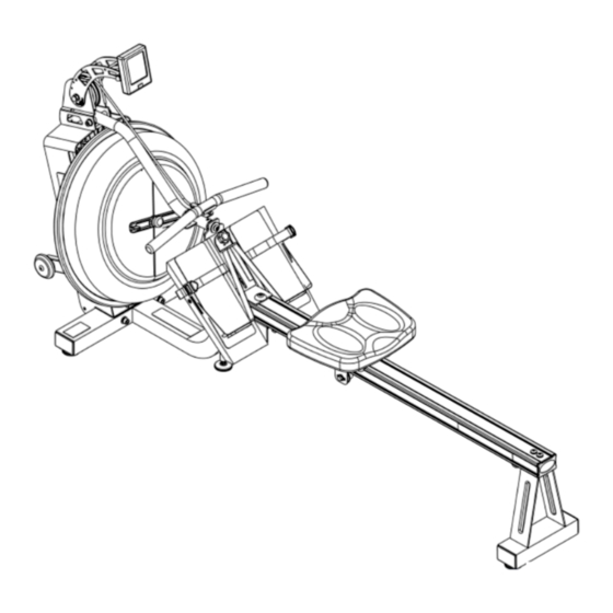
- Page 1 Owners Manual FR-E216...
-
Page 2: Table Of Contents
Contents Training with the E-216 1. As with any piece of fitness equipment, consult a physician 1. Contents of E-216 Pack. before beginning your E-216 Rower exercise program. 2. E-216 assembly instructions. 2. Follow instructions provided in this manual for correct foot position and basic rowing techniques. - Page 3 1. Upper mainframe and tank 10. 2X AA batteries 19. Vertical seat rail bolt support bracket 28. M10X90mm bolt (lower to upper frame) 2. Lower mainframe 11. 8X Chlorine tablets 20. Rear end cap 29. M10X80mm S-bend bolt 3. Seat Rail 12.
-
Page 4: E-216 Assembly Instructions
E-216 Assembly Instructions Step 3. Attach lower frame to upper frame starting with middle M10x70mm bolt and spring washer. Do not tighten Step 1. Remove contents from box, and lay upper frame (tank assembly) on its back. Note: Use protected surface to prevent scratching Perspex cover. - Page 5 Once the lower frame is se- curely attached, continue steps 5-9 of the assembly from this position. M10x70mm bolt, Plastic dome cap, and Vertical seat rail support bracket Footplate Seat Rail Step 5: Insert the seat rail into the foot- Plastic dome cap M10x 70mm bolt plate until the front of the seat rail just...
- Page 6 Step 6. Install completed footplate/seat rail Seat Rail assembly onto the main frame as shown, us- ing M10X140mm bolt, M10 Nylock nut and 2x M10 washers. Insert the 140mm footplate bolt with a stan- dard M10 washer through the mainframe, Hold seat rail/Footplate footplate and seat rail as shown left.
- Page 7 Rear Leg Step 9. Attach the rear seat rail leg using 2x M8X60mm bolts, M10 washers and internal support bracket. Insert rubber seat rail Step 7. Install the rower seat. (Make sure seat indentation is end cap (not facing rearward as pictured) shown).
-
Page 8: Caution
Carefully lower the rower to its nor- mal operating position to complete assembly with S-bend installation and frame tensioning bolt. Step 10. Install rear of S-bend onto the upper frame using M10x80mmbolt, M10Nylock and 2xM10washers. Step 11. Attach the S-bend to the foot- plate as shown. -
Page 9: Caution
Tank Filling and Water Treatment Fill tank as shown left. Use the right 1. Filling requires a large bucket (not supplied) and the Fluid plug only for fill- Rower siphon (included). Filling will take approximately 7.6 ing. liters of water. Fill with adjuster 2. -
Page 10: How To Row/Operational Instructions
How to row. 1. Begin the stroke comfortably forward and push strongly back with your legs while keeping your arms and back straight. 2. Begin to pull your arms back as they pass over your knees and continue the stroke through to completion rocking slightly back over your pelvis. -
Page 11: Operational Instructions
Operational Instructions: Operational Instructions Heel support Adjustment: The E-216 has a unique and easy to use Heel Support Ad- juster (Pat. Pend.). Simply loosen the footplate knob and slide the Adjuster up or down to required position. This Caution should place the ball of your foot directly under the horizontal Foot Straps. -
Page 12: The E-216 Computer
Computer Instructions The E-216 Computer: TIME: Auto start elapsed time. E-216 500M TIME: Time to row 500 meters, updated at the completion each stroke. PULSE: Requires optional receiver and chest strap. SPM: Strokes per minute updated each stroke. WATTS: Indication of watts at resistance level16. CAL HOUR: Updated each stroke. -
Page 13: Long Term Water Treatment/Basic Operation
For replacement tablets, con- of Dyneema make it extremely useful in harsh environments, such tact your local First Degree Fitness distributor. as sailing, climbing, fishing lines, body armor, etc. It is quite literally stronger than steel. The 6mm Dyneema rope used on the E-216 is Water treatment schedules for the E-216 will vary according rated in excess of 1,000kg. - Page 14 Note that a light “fuzz” instructions provided in the is perfectly normal for “Changing the Dyneema rope” Dyneema rope and will not section of in the service section of affect performance or longev- the First Degree Fitness website at ity in any way. www.firstdegreefitness.com...
-
Page 15: Troubleshooting Guide
Troubleshooting Guide Fault Probable Cause Solution Water changes color or becomes Rower is in direct sunlight or has not Change rower location to reduce direct exposure to cloudy. had water treatment. sunlight. Add water treatment and blue dye or change tank water as directed in the water treatment section of this manual. - Page 16 Replacing the E-216 bungee shock cord Step 1. Remove the Perspex Step 2. Move the rowing handle Step 3. Unwrap the bungee cover from rear of upper from the S-bend handle catch to cord from all of the bungee frame. Disconnect sensor a point where it is resting on top pulleys.
- Page 17 Replacing the E-216 bungee shock cord Step 4. Next, remove the magnetic ring. To loosen the rear mainshaft bolt holding the magnetic ring in place, it is neces- sary to keep the mainshaft and impeller assembly from turning with the bolt. Open the right rear tank plug, and insert a wrench wrapped in a lint free cloth (to protect the electroplating finish on the blades) to catch the impeller blade and allow the rear mainshaft bolt to be loosened as shown below right with a 6mm Allen key.
- Page 18 Replacing the E-216 bungee shock cord Step 5. After removing the magnetic ring, the Step 6. Once the bungee cord is in position, make bungee cord will be accessible. Pull through the two wraps on the rope/bungee pulley in a clockwise rope/bungee pulley and remove.
- Page 19 Replacing the E-216 bungee shock cord Bungee wrapping in order: 1. Rope/bungee pulley to upper rear right bungee pulley. 2. Upper rear right to lower rear right and left rear pulleys. 3. Lower left rear to upper left rear pulley. 4.
- Page 20 Replacing the E-216 bungee shock cord Reattach the magnetic ring. Tighten securely. Finally, reattach the sensor lead and replace the Per- spex rear cover. Finish the bungee rewrap by tying off the bungee. You may elect to not use a tie wrap as the metal tab is designed as a stand alone at- tachment point.
-
Page 21: Parts List
Parts List/Exploded Diagram: 73009 D25-C-Clip 73910 Magnetic Ring Item Part # Description 73019 PVC Cover 70200 Lower Frame 10170 Washer M4 70700 Foot Plate 10070 Screw M4x10 70410 Tensioning Bolt 73005 M3x8 Screw 60700 Seat Assembly 73900 Sensor Assembly 60601 Heel Adjuster Knob External Plate 63501 Rower Handle... - Page 23 Item Part Number Description QTY Item Part Number Description 70102 Left Main Frame 10084 Bungee Pulley Lower Tank Bracket 73104 73411 Pulley Shaft Bolt 73105 Upper Tank Bracket-Left 10086 C Clip RTW-35 Upper PVC Cover Bracket 70111 73008 M12*70 bolt Bungee Hook 70113 73003...
-
Page 24: Warranty
Metal Frame – 5 Year Limited Warranty First Degree Fitness will repair or replace the metal Main Frame of the Rower should it fail due to any defect in materials or workmanship within 5 years of the original purchase. Warranty does not apply to frame coating.
Need help?
Do you have a question about the Fluid FR-E216 and is the answer not in the manual?
Questions and answers