Table of Contents
Advertisement
Quick Links
Advertisement
Table of Contents

Summary of Contents for Yoko Technology 4CH MJPEG DVR
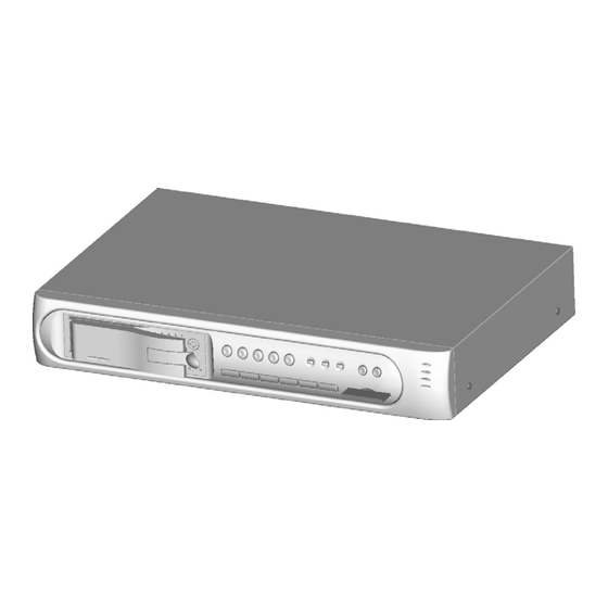
- Page 1 4CH MJPEG DVR U S E R M A N U A L...
-
Page 2: Table Of Contents
INDEX 1. SAFETY PRECAUTIONS ..............3 2. INTRODUCTION ................. 4 2.1 P ............. 4 RODUCT NTRODUCTION 2.2 A ................4 PPLICATION 3. FEATURES ................... 5 4. PACKING LIST ..................6 5. INSTALLATION ................... 7 5.1 C ..........7 ONNECTORS ON THE ANEL 6. - Page 3 9.1 N DVR S ............... 38 ETWORK ETUP 9.2 C DVR ............ 39 ONNECTING ETWORK 9.3 M ................44 ISPLAY 9.3.1 L ................. 44 ISPLAY 9.3.7 Q ..............47 UALITY ETTING 9.3.8 R ............. 48 ESOLUTION ETTING 9.3.9 A ..............48 DVANCE ETTINGS 9.4.
-
Page 4: Safety Precautions
1. SAFETY PRECAUTIONS WARNING: Alert the user to the presence of un-insulated “dangerous voltage”. CAUTION: Alert the user the presence of important operating and maintenance (Servicing) instructions in the literature accompanying the appliance. The power cord is the main power connection. Therefore, constantly plug and unplug of the power cord might result in malfunction of the product. -
Page 5: Introduction
2. INTRODUCTION 2.1 Product Introduction World leading technology not only perfect for office safety, personnel home security, public environments, industry surveillance, school, and so on. Quick and simple installation, the best choice for your own ultimate protection. The sate-of-art 4-channel digital recording system, equipped with advanced embedded CPU operating system, powerful MJPEG compression technology. -
Page 6: Features
3. FEATURES Auto video input detection Auto detects video input (NTSC/ PAL) and supports combine use of color and b/w cameras. Supports high quality digital video recording Adopts M-JPEG compression technology (NTSC: 30fps/ PAL: 25fps). Video Size Video Resolution • NTSC: 640x 224 •... -
Page 7: Packing List
4. PACKING LIST Check to make sure all of the items shown below are included in your product package. If something is missing, contact your dealer as soon as possible. (1) DVR (digital video recorder) (2) Power adapter (3) Power Cord (Plug type differs depending on area) -
Page 8: Installation
5. INSTALLATION 5.1 Connectors on the Rear Panel Please setup the connection by following the illustration shown below (network is an optional function):... -
Page 9: Name And Function Of Each Part
6. NAME and FUNCTION of EACH PART 6.1 Front Panel Buttons and Controls 1. Removable HDD Box 2. Front Panel Button Definition : Press this button under monitoring or quad mode to show quad (2) QUAD display. : Press this button under monitoring or record mode to show (3) CH 1 CH 1 in full-screen. - Page 10 (13) PLAY LED : LED lights while playing playback. (14) MENU LED : LED lights when entering setup menu. (15) STOP LED : LED lights when entering stop mode. (16) REC : Press this button under monitoring mode to start recording. (17) STOP : Press this button under playback to return to start monitoring.
-
Page 11: Rear Panel Buttons And Controls
6.2 Rear Panel Buttons and Controls (1) RJ45: Internet connection terminal (optional). (2) Video Input [VIDEO IN]: Connect to cameras. (3) DC 12V (4A) [Power Input terminal]: power socket. (4) S-Video Output [S-VIDEO OUT]: Connect to the monitor. (5) Video Output [VIDEO OUT]: Connect to the monitor. (6) Video Loop [VIDEO LOOP]. -
Page 12: Operating Procedure
7. OPERATING PROCEDURE 7.1 Power On Each time after power on, DVR will auto-detect its peripherals (self-testing, warm-up, auto detects the hard disk and starts CF-card testing, and etc.) The system will detect the video input and judge whether the video system is NTSC or PAL. -
Page 13: Record Display
7.3 Record Display Note:CH1: No block figure next to CH1 indicates that it is not recording. EACH: Record Type QUAD: Record Type (T): TIMER RECORD (A): ALARM RECORD (M): MIX RECORD ( ): Currently under recording. VIDEO LOSS: Video input unable to be detected. CAMERA1: Name for CH 1. -
Page 14: Playback Display
7.4 Playback Display TIME SEARCH HARD DRIVE: MASTER 03/11/27 18:20:42 - 03/11/27 19:32:32 >01 TIME 2003/11/27 18:20:42 02 TIME 2003/11/27 16:43:56 03 TIME 2003/11/27 15:07:11 <,> ) MOVE (ENTER)CHANGE (PLAY)PLAY (MENU) EXIT (FF)SELECT EVENT OR TIME >01 TIME Total 7 >07 1. -
Page 15: Note
7.5 Note! 1. “Auto Sequence” function operates only during recording or under live status (Dwell Time: 5 seconds). Sequencing will bypass a channel with video loss if programmed accordingly (Example: Video Loss occurs on CH3, sequencing order: CH1 CH2 CH4 QUAD). 2. -
Page 16: System Setup
8. SYSTEM SETUP 8.1 Menu (3) > SYSTEM SETUP CAMERA SETUP RECORD SETUP BUZZER SETUP EVENT LIST CF CARD SETTING HARD DRIVE SETUP (4) PRESS (< >), THEN (ENTER) PRESS (MENU) TO EXIT (1) MAIN MENU: Item subject (First menu layer does not have a subject). (2) Menu Layer Indication: The device consists of four menu layers. -
Page 17: System Setup
8.2 System Setup SYSTEM SETUP > TIME SET PASSWORD SET LOARD DEFAULT VERSION V1.0 PRESS(< >), THEN (ENTER) PRESS (MENU) TO EXIT 1. Cursor (>) position indicates the current function selected. 2. Press button to move the cursor. 3. Press ENTER button to proceed. 4. -
Page 18: Time Set
8.2.1 TIME SET TIME 2005/01/11 17 23 06 PRESS (< >), THEN (ENTER) PRESS (MENU) TO EXIT 1. Cursor (^) position indicates the current time and date selected. 2. Use button to move the cursor. 3. Use ENTER button to setup time and date. 4. -
Page 19: Password Set
8.2.2 PASSWORD SET PASSWORD SETUP > PASSWORD CHANGE MENU PASSWORD STOP REC PASSWORD PRESS (< >), THEN (ENTER) PRESS (MENU) TO EXIT 1. Cursor (>) position indicates the current function selected. 2. Use button to move the cursor to the desired item . 3. -
Page 20: Password Change
8.2.2.1 PASSWORD CHANGE CURRENT PASSWORD _ _ _ _ _ _ PASSWORD _ _ _ _ _ _ CONFIRM PASSWORD _ _ _ _ _ _ PRESS (MENU) TO EXIT 1. Press ENTER button to show the display above. 2. Enter the current password (CURRENT PASSWORD). 3. -
Page 21: Load Default
8.2.3 LOAD DEFAULT PRESS (ENTER) TO RESET PRESS (MENU) TO EXIT 1. Press ENTER button to show the display above. 2. Press ENTER button the message ALL SETTING DATA IS INITIALIZED will be displayed by flashing 3 times, and returns to default value. When reset procedure has been completed, the message DVR RESET COMPLETED TURN OFF AND ON THE DVR will be displayed, please restart the DVR. -
Page 22: Camera Setup
8.3 Camera Setup CAMERA SETUP > CAMERA ENABLE 1234 CAMERA TITLE ---- CAMERA SETTING CH1 TITLE CAMERA1 CH2 TITLE CAMERA2 CH3 TITLE CAMERA3 CH4 TITLE CAMERA4 PRESS (< >), THEN (ENTER) PRESS (MENU) TO EXIT 1. Cursor (>) position indicates the current function selected. 2. - Page 23 CH1 TITLE CAMERA1 12345678 “V” indicates the position of the cursor. Press button to move the cursor, and press ENTER button to change the title (maximum 8 characters). 8. All channel titles are setup the same way. Once the user formats the hard disk drive, the camera title returns to its default setting (CAMERA1/ CAMERA2/ CAMERA3/ CAMERA4).
-
Page 24: Camera Setting
8.3.1 CAMERA SETTING CAMERA SEUP > CAMERA SELECT RECORD ENABLE MOTION DETECTION MOTION SENSITIVITY CONTRAST BRIGHTNESS PRESS (< >), THEN (ENTER) PRESS (MENU) TO EXIT 1. Cursor (>) position indicates the current function selected. 2. Press button to move the cursor to the desired item. 3. -
Page 25: Record Setup
8.4 Record Setup RECORD SETUP > RECORD TYPE EACH VIDEO QUALITY NORMAL TIME RECORD FRAMERATE MOTION RECORD FRAMERATE SENSOR RECORD FRAMERATE ALARM REC TIME RECORD MODE PRESS (< >), THEN (ENTER) PRESS (MENU) TO EXIT 1. Cursor (>) position indicates the current function selected. 2. -
Page 26: Record Mode
10. SENSOR RECORD FRAMERATE: Press ENTER button to setup different recording speed, when a sensor device has been triggered (this setup is only active when the recording speed under schedule record mode is setup to “M”(Mix) or “A” (Alarm)). NTSC:30,15,10,7,5,4,3,2,1fps. PAL :25,12,8,6,4,3,2,1fps. -
Page 27: Buzzer Setup
4. Use MENU button to exit “SECHDULE RECORD MODE” selection. 5. T: Time, indicates continuous record. 6. M: TIME+MOTION+SENSOR. (1) When motion has been detected, it will be recorded by “Motion Record Speed”. (2) When sensor has been triggered, it will be recorded by “Sensor Record Speed”. - Page 28 2. Press button to move the cursor to the desired item (time). 3. Press ENTER button to proceed. 4. Press MENU button to exit “BUZZER SETUP” selection. 5. “BUZZER SETUP is situated on the second menu layer. Under this menu layer user may setup “ALARM ALERT”, “...
-
Page 29: Sensor Type
8.5.1 SENSOR TYPE: SENSOR SETUP > CHANNEL-1 NOT INSTALLED CHANNEL-2 NOT INSTALLED CHANNEL-3 NOT INSTALLED CHANNEL-4 NOT INSTALLED PRESS (< >), THEN (ENTER) PRESS (MENU) TO EXIT 1. Cursor (>) position indicates the current selected position. 2. Press button to move the cursor to the desired item (CH1~CH4). 3. -
Page 30: Event List
8.6 Event List EVENT LIST > TIME SEARCH EVENT SEARCH PRESS (< >), THEN (ENTER) PRESS (MENU) TO EXIT 1. Cursor ( ) position indicates the current function selected. > 2. Press button to move the cursor to the desired item. 3. -
Page 31: Time Search
8.6.1 TIME SEARCH TIME SEARCH 05/01/13 19 27 16 BEGIN TIME 05/01/13 19 27 16 END TIME 05/01/15 15 00 06 PRESS (< >), THEN (ENTER) PRESS (MENU) TO EXIT 1. TIME SEARCH: Displays system recording time (begin and end). 2. -
Page 32: Event Search
8.6.2 EVENT SEARCH EVENT SEARCH BEGIN 05/01/15 15 00 01 05/01/15 15 00 06 > 01 ALARM 2005/01/15 15 00 01 02 MIX 2005/01/15 14 00 01 03 TIME 2005/01/15 13 00 01 04 ALARM 2005/01/15 12 00 01 PRESS (< >), THEN (ENTER) PRESS (MENU) TO EXIT 1. -
Page 33: Cf Card Setup
8.7 CF Card Setup CF CARD SETUP > COPY FORMAT/ERASE TOTAL CAPACITY 512MB REMAINING CAPACITY 100MB PRESS (< >), THEN (ENTER) PRESS (MENU) TO EXIT 1. Cursor ( ) position indicates the current function selected. > 2. Press button to select the desired item. 3. -
Page 34: Select Time
8.7.1 SELECT TIME SELECT TIME > DAY 05/01/15 15 00 01 BEGIN TIME 15 00 06 END TIME COPY PRESS (< >), THEN (ENTER) PRESS (MENU) TO EXIT 1. SELECT TIME: Displays the newest event date, begin and end time. 2. -
Page 35: Copy
8.7.1.1 COPY (1) SELECT DATA 10MB (2) ESTIMATED TIME 2 Minute (3) START COPY (4) CAPACITY IS NOT ENOUGH (5) 10% COPIED (6) PRESS (ENTER) TO COPY (7) PRESS (MENU) TO EXIT 1 Data capacity. 2 Estimated time to complete data copy. 3 Request to confirm copy. -
Page 36: Format/ Erase
8.7.2 FORMAT/ ERASE PASSWORD INPUT ------ 1. When proceeding “FORMAT/ ERASE” function, the above display will be shown. 2. When password entered is correct, the screen will display the message “PASSWORD CORRECT”, “CF CARD FORMATED” (flashes 3 times), indicates CF Card format is successful. 3. -
Page 37: Hard Drive Setup
8.8 Hard Drive Setup HARD DRIVE SETUP > DISK FULL OVERWRITE HDD SIZE 120103MB HDD USED 13321MB HDD FORMAT PRESS (< >), THEN (ENTER) PRESS (MENU) TO EXIT 1. Cursor ( ) position indicates the current function selected. > 2. Press button to select the desired item. -
Page 38: Hdd Format
8.8.1 HDD FORMAT: PASSWORD INPUT ------ 1. When proceeding “HDD FORMAT” function, the above display will be shown. 2. When password entered is correct, the screen will display the message “HDD FORMATTED” (flashes 3 times), indicates hard disk format is successful. 3. -
Page 39: Remote Control (Optional)
9. REMOTE CONTROL (Optional) 9.1 Network DVR Setup Before installing the Network DVR, you need to first setup an IP Address, connect it to the ADSL Modem or LAN Hub, and use IPEdit.exe to test the DVR. Note: Before using PPPoE and DDNS connection method, one must first setup an IP Address (using IPEDIT.exe). -
Page 40: Connecting Network Dvr
9.1.2 Online without DHCP Server 1. Use IPEdit.exe to find the installed Network DVR. 2. The Internet DVR without IP allocated by DHCP will have a default IP Address of 169.254.1.13. 3. Select this Internet DVR on Camera List Window. 4. -
Page 41: Online Using Intranet Or Fixed Ip
9.2.1 Online using Intranet or Fixed IP Setup similar to “9.1 Network DVR Setup” . 9.2.2 Online using ADSL (PPPoE) Router Setup similar to “9.4.3.3 Connect to ADSL by PPPoE mode”. 9.2.3 Online using DDNS Server The DDNS service provides the dynamic IP to users to gain access to resources connected to the Internet via a cable or DSL connection. -
Page 42: Install Activex
9.2.4.1 Install ActiveX Before entering remote connection, please install ActiveX and check your browser setup by following the procedures below: a. Open Internet Explorer under “Tools”, select “Internet Options”. Tools Internet Options b. Select “Security”, and then press “Custom Level”. Security ->... - Page 43 Start-up ActiveX Control...
- Page 44 The graphic below will be shown when first time installing ActiveX Mode. Please, select “Yes” to accept installation. Download ActiveX Control Live view will be displayed when installation is successful. Live display under ActiveX mode...
-
Page 45: Main Display
9.3 Main Display Remote control DVR - Main Menu Live Display DVR Control Button Video Setup Configuration: Enter detail setup Recording: Displays recording setup menu (for video recording). Snapshot: Pop-up window displays live images, right mouse click to save. Note! To view complete interface, PC resolution must be adjusted to 1024*768. 9.3.1 Live Display View/ Make changes on image display Rotate/ Make changes on image direction... - Page 46 9.3.2 View Two types of display method: a. Resizable: Adjustable image size. b. Actual size: The actual image size. 9.3.3 Rotate Four types of rotate settings: a. Rotate 0: Default state b. Rotate 180: Rotate the image by 180 degrees. c.
-
Page 47: Save As Jpeg
9.3.4 Image Recording Image Recording Setup Display: Save as JPEG: Save as picture file Save as AVI: Save as AVI animation file Save as JPEG: No Limit: Unrestricted image storage (continuous). Number: Image storage according to “number”. Save interval: Image storage according to “1/10 second” (e.g.: Enter “10”, then 1 frame is stored per second. -
Page 48: Quality Setting
9.3.5 Save Current Picture Select to save live images. 9.3.6 DVR Control Setup Supports DVR remote control function (Please refer to 6-1 Front Panel Buttons and Controls, on page 8). 9.3.7 Quality Setting Network DVR provides 5 image quality settings. The user can select the quality setting from the “Quality”... -
Page 49: Resolution Setting
9.3.8 Resolution Setting Network DVR provides six resolution settings. The user can select the quality setting from the “Resolution” list box. 176x144 160x120 320x240 352x288 640x480 704x576 Note! The device supports auto video system detection (NTSC/ PAL). 9.3.9 Advance Settings Network DVR provides the advanced settings for the following: Brightness Contrast... -
Page 50: User Setting
Reboot DVR: The system need 20 seconds to reboot the DVR (Rebooting does not effect the recording function). FirmWare update (Please refer to 6.7). ReStore Factory Default 9.4.2 User Setting User Authorization Setting Add User or Change Password Delete User Account Current Users User Setting Display 9.4.2.1 User Authorization Setting... -
Page 51: New User/ Change Password
9.4.2.2 New user/ Change Password Enter a new user name and password information to create a new user account, or enter an existing user account, then set a new password to replace the old password, and select “OK” to create the account or change password. After selecting “OK” button, the “Current User List”... -
Page 52: Dhcp
9.4.3.2 DHCP The “DHCP” is automatically set as the default network setting of the Network DVR. When a Network DVR is connected into the LAN, it will issue DHCP packets to request an IP address that is dynamically assigned by the DHCP server. If it is unable to get a DHCP address on a limited tries, the Network DVR will assign a default IP address such as “169.254.1.13”. -
Page 53: Ddns Setting
1. Power off Network DVR. 2. Connect Network DVR directly to the ADSL modem (using RJ-45 Ethernet port). 3. Power-up Network DVR. 4. Network DVR start dialing. 5. Once connected, mail the IP address information to the preset e-mail address. 6. - Page 54 To setup follow the steps below: 1. Register at DDNS Server: http://www.dyndns.org. 2. Apply domain name. 3. Click the “Enable” button. Enter “UserName” and “Password” with “DomainName”. DDNS Setting After registering the domain name, please enter the information supplied by the administrator to the Network DVR DDNS Account Setting.
-
Page 55: Firmware Update
9.4.5 Firmware Update When new firmware (bin file) is supplied, you may update the new version firmware (bin file) to your PC by following the procedures below: Select the Firmware to be Updated Uploading the Selected Firmware Press “Upload” button to display the message below, and follow the instruction to make the necessary setup. - Page 56 Press “here” button (1) to update Firmware. Press “here” button (2) to delete the file. The message below displays the writing progress of the firmware update. When Firmware update is completed, it will show 100%, and a message “Click here to reboot DVR browser”...
-
Page 57: Cf Card/ Hdd Player Software Description
10. CF Card/ HDD Player Software Description PC Player Software System Requirement OS (Operating System) Windows 2000/ XP or later. Use your PC to install DirectX (version DirectX 7.0 or above). Hardware Requirement CPU 1.0 GHz or higher. RAM 256 Mbyte or higher. 1. - Page 58 3. Software Playback Interface Description A. User Interface Play System System Status Figure 1 When the system detects stored materials (HDD or CF card), the above graphic (Figure 1) will be shown. User may operate the function buttons to make necessary playback adjustment or store recordings onto the PC.
- Page 59 No Recording Materials Stored Recording Material Stored Fast Rewind Step Back One Frame Rewind Pause Playback Forward Step Forward One Frame Fast Forward Quad split screen display CH1 Full Screen Display CH2 Full Screen Display CH3 Full Screen Display CH4 Full Screen Display Click this button to capture images as BMP file, graphic shown by “Figure 2”...
- Page 60 Figure 2 Figure 3...
- Page 61 Figure 4 Figure 5...
- Page 62 B. Parameter Setup To setup the parameter, click “Parameter Setup” button to show the graphic display below (Figure 6): Figure 6...
-
Page 63: Troubleshooting
11. TROUBLESHOOTING Question Answer Why can’t the device read the hard Please reinstall the hard disk, make sure that it disk? is properly connected, and reboot the device. Why can’t the device read the CF Please reinsert the CF card, make sure that it card? is properly connected and reboot the device. -
Page 64: Specifications
12. SPECIFICATIONS Format NTSC/EIA or PAL/CCIR Compression Modified M-JPEG Video Input 4CH, BNC Output 1 x BNC, 1 x S-Video Resolution 720 x 480 (NTSC), 720 x 576 (PAL) Frame Rate Max. 120/100 fps (NTSC/PAL) Display Division Single, Quad, Sequence Resolution Max. - Page 65 MEMO...
Need help?
Do you have a question about the 4CH MJPEG DVR and is the answer not in the manual?
Questions and answers