Table of Contents
Advertisement
Quick Links
Advertisement
Table of Contents

Summary of Contents for JSC Elektromotus Emus
- Page 1 User’s manual Revision 1 In this user‘s manual you will find a list of characteristics, setup and installation steps and recommendations for the EMUS Battery Management System. This document should be read before setting up your EMUS BMS. JSC Elektromotus, 2011...
-
Page 2: Table Of Contents
Installation & setup ..................... 6 Connect 12V power source ................6 Connect the USB ....................6 Start the EMUS BMS Control Panel ..............7 Configure cell count and type ................8 Install Cell Modules ..................9 Connecting Charging and Battery low indication .......... 13 Connecting sound buzzer ................ -
Page 3: Introduction
Display Module (optional add-on). Control Unit also has a USB interface for firmware updates, configuration, which is used to connect it to a PC to configure the BMS via special EMUS BMS Control Panel software. -
Page 4: Standard Package Contents
EMUS BMS User‘s manual EMUS BMS Control Unit also has a connection to Current Sensor Module (optional add-on) which enables the EMUS BMS to act as a State Of Charge (SOC) meter allowing user to monitor remaining battery charge and plan a trip or operation. - Page 5 USB-configurable: free EMUS BMS Control Panel application for Windows • OS is supplied to update the firmware of the EMUS BMS, configure it, read statistical data and observe each cell in real time. One-wire digital interface between Cell Modules: the minimum of wires •...
-
Page 6: Specifications
EMUS BMS User‘s manual Specifications Parameter Value 8 – 20 V Control Unit supply voltage 4 – 1300 V Battery pack voltage 2 – 255 pcs. Series cell count 2 – 5 V Cell operating voltage 1.5 A Cell balancing current... -
Page 7: Installation & Setup
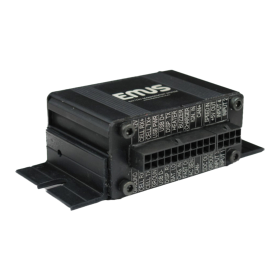
Connect 12V power source The EMUS BMS Control Unit needs 12 Volts DC power from vehicle's auxiliary battery or other 12V source. Connect 12V battery's negative (-) tab to “GROUND” and battery’s positive (+) tab to “+12V” wires of the 22-pin connector on EMUS BMS Control Unit. -
Page 8: Start The Emus Bms Control Panel
EMUS BMS User‘s manual Start the EMUS BMS Control Panel EMUS BMS Control Panel software application can be found on USB Flash drive supplied with the EMUS BMS or downloaded from our website www.elektromotus.eu. When started, application will initiate a connection to the EMUS BMS. -
Page 9: Configure Cell Count And Type
The connection of the cells will be covered in the next chapter, but before that we will configure the number of cells for EMUS BMS that it would expect to see on the battery after installation. The Number of Cells is configured by selecting Configuration page and Cells tab. -
Page 10: Install Cell Modules
EMUS BMS User‘s manual Install Cell Modules There are 4 types of EMUS BMS Cell Modules to allow nice and tidy installation on the battery pack: Bottom, types A and B, Top. The type of the module is printed on the module itself. Bottom cell module is dedicated to be installed on the cell which has negative (-) terminal of the whole battery pack. - Page 11 4) Washer 5) Spring washer 6) Bolt This applies both for EMUS BMS Cell Module itself (negative (-) contact) and it‘s red wire (positive (+) contact). WARNING: Please pay special attention to the cell and module’s polarity! Cell Module must be bolted onto cell's negative (-) terminal and module’s wire must be bolted onto positive (+) terminal of the cell.
- Page 12 EMUS BMS User‘s manual Bottom and Top Cell Modules have additional connections that go to EMUS BMS Control Unit: Bottom Cell Module's “RX+” and “RX-” signals should be connected via twisted pair to Control Unit's “CELL RX+” and “CELL RX-” wires correspondingly. It is...
- Page 13 Modules are installed and connected, the EMUS BMS Control Unit should be able to detect the cells. The EMUS BMS Control Panel's Cells status tab should show correct number of cells of the stack and their parameters in the graphs.
-
Page 14: Connecting Charging And Battery Low Indication
6W 12V lamps. LEDs can also be used but they must be connected with corresponding value resistor in series. Lamp's one terminal or LED's “-” side must be connected to EMUS BMS Control Unit's output. Other lamp's terminal or LED's “+” side must be connected to +12V external power source. -
Page 15: Connecting Ignition And Fast Charge Input Switches
Connecting non-CAN charger Non-CAN charger does not have the benefits of CAN charger but may also be used with EMUS BMS. There are two signals provisioned for such charger connection: “AC SENSE” and “CHARGER”. “AC SENSE” is the input which senses the charger connection to AC mains power source. -
Page 16: Connecting Can Charger
Once the CAN charger is properly connected to Control Unit via CAN bus it may be verified by plugging it into AC mains. EMUS BMS Control Unit will detect the powered-up charger via CAN bus and start a charging process which can be checked by Charging Indication lamp, graphical display or via EMUS BMS Control Panel application on PC. -
Page 17: Connection Of Ipaq As Display Unit
When all battery cells and EMUS BMS Cell Modules are installed, user must initiate a temperature calibration command. To do so, connect the EMUS BMS Control Unit to PC’s USB port, start the EMUS BMS Control Panel application and navigate to Configuration page, Cells tab. There you will find a Calibrate Temperature button and empty field next to it. -
Page 18: Cell Voltage Configuration
Status page, Cells tab, Temperatures graph. Cell voltage configuration EMUS BMS is designed to work with wide range of battery cells with operating voltages in between 2 and 5 V, including LiPO, Li-Ion, LiFePO4 and others. Different cell types operate at different voltages and these parameters must be set for proper operation of EMUS BMS. - Page 19 To be on the safe side, set a value of, say, 2°C, to give it a little margin of error. EMUS BMS will turn on the battery heater (if one exists) and wait until cell temperatures reaches the value set, before charging the pack.
-
Page 20: Configuring The Charger
EMUS BMS User‘s manual Configuring the charger To configure timing of the EMUS BMS, connect the EMUS BMS Control Unit to PC’s USB port, start the EMUS BMS Control Panel application and navigate to Configuration page, Charger tab. Charger Type dropbox selects a type of charger: with or without CAN interface. -
Page 21: Configuring The Timing
Configuring the timing To configure timing of the EMUS BMS, connect the EMUS BMS Control Unit to PC’s USB port, start the EMUS BMS Control Panel application and navigate to Configuration page, Timing tab. - Page 22 EMUS BMS User‘s manual Maximum Pre-Charge Duration specifies the amount of time for the EMUS BMS to try to pre-charge cells up to Minimum Allowed Voltage, (specified in Cells tab) if the battery pack is over-discharged. If this phase takes longer than a couple of hours it may indicate a Cell Module malfunction of a bad cell.
-
Page 23: Firmware Updates
Once a new firmware image (*.img) file is downloaded, save it on your desktop. To update the EMUS BMS, connect the EMUS BMS Control Unit to PC’s USB port, start the EMUS BMS Control Panel application and navigate to Update page. - Page 24 EMUS BMS User‘s manual File information appears in Software section. If versions of the file and firmware running in the EMUS BMS Control Unit are the same, it is up to date and does not need an update. To start the update, click on Start update button and wait until update process completes and successful firmware update is confirmed.
Need help?
Do you have a question about the Emus and is the answer not in the manual?
Questions and answers