
Subscribe to Our Youtube Channel
Related Manuals for DEC RAID Array 3000 storage subsystem

Summary of Contents for DEC RAID Array 3000 storage subsystem
- Page 1 RAID Array 3000 Storage Subsystem Hardware User’s Guide EK–SMCPO–UG. A01 Digital Equipment Corporation Maynard, Massachusetts...
- Page 2 Equipment Corporation. Possession, use or copying of the software described in this publication is authorized only pursuant to a valid written license from Digital Equipment Corporation or an authorized sublicensor. Digital Equipment Corporation makes no representation that the use of its products in...
-
Page 3: Table Of Contents
Contents Revision Record ....................ix About This Guide ...................xi Product Overview Product Description................1–1 Pedestal Features...................1–4 Pedestal Cabinet..................1–4 Pedestal Components ................1–6 1.4.1 StorageWorks Building Blocks (SBBs)..........1–6 1.4.2 RAID Array Controller ..............1–6 Pedestal Power Supplies ..............1–7 1.4.3 Uninterruptable Power Supply ............1–7 1.4.4 Environmental Monitor Unit (EMU)..........1–8 1.4.5 UltraSCSI Bus ...................1–9 1.4.6... - Page 4 RAID Array 3000 Storage Subsystem RAID Array Controller (continued) 2.6.5 RAID 5.................... 2–16 2.6.6 JBOD ....................2–18 System Parameters................2–18 Redundant Operation ................2–20 2.8.1 Initialization ..................2–20 2.8.2 Message Passing................2–20 2.8.3 Failover................... 2–20 Environmental ..................2–21 2.9.1 Backup Power Management ............2–21 2.9.2...
- Page 5 Contents Expansion Pedestal Option Product Description................4–1 Expansion Pedestal Cabinet..............4–2 Expansion Pedestal Components ............4–4 Reconfiguring Base Pedestal UltraSCSI Bus .........4–5 Second Controller Option Introduction...................5–1 Installation Procedure................5–2 Figures 1–1 RAID Array 3000 Pedestal Enclosure (Drives Optional) .......1–2 1–2 Pedestal Front Panel Major Components ..........1–5 1–3 Pedestal Rear Panel Power Supplies ............1–5 1–4...
- Page 6 RAID Array 3000 Storage Subsystem Figures (continued) 3–8 Remove Screw and Panel..............3–14 3–9 Location of SCSI Bus Configuration Switch ........3–15 3–10 Configuration Switch ................3–15 3–11 Remove Controller................3–16 3–12 Release Locking Clips ................ 3–17 3–13 Remove Installed Memory Modules............ 3–17 3–14...
- Page 7 Contents Tables 1–1 RAID Array 3000 Part Numbers and Model Descriptions......1–3 1–2 Pedestal Specifications................1–12 1–3 Pedestal Physical and Power Specifications......... 1–13 2–1 Controller Specifications...............2–4 2–2 LED/Reset Switch Interface ..............2–6 2–3 RAID Levels Supported ..............2–10 2–4 Pedestal RAID Set Restrictions ............2–10 2–5 RAID 0+1 Example................
-
Page 9: Revision Record
The following revision history lists all revisions of this publication and their effective dates. The publication part number is included in the Revision Level column, with the last entry denoting the latest revision. This publication supports the StorageWorks RAID Array 3000 Storage Subsystem. Revision Level Date Summary of Changes EK–SMCPO–UG. -
Page 11: About This Guide
Chapter 1: Product Overview Product Overview provides an overview and a physical hardware description of the single pedestal RAID Array 3000 storage subsystem. It includes the major features, a brief description of the major components, and the specifications for the pedestal. - Page 12 RAID Array 3000 Pedestal Enclosure Chapter 4: Expansion Pedestal Option Expansion Pedestal Option describes the major features and characteristics of the pedestal expansion kit option. It also explains how to reconfigure the SCSI bus in the base pedestal to accommodate the added storage capability of the expansion pedestal.
- Page 13 About This Guide Conventions ( continued Table 3 Nomenclature Convention RAID Advisory Board Description RAID Array 3000 Usage RAID 0 STRIPset RAID 1 MIRRORset RAID 0+1 STRIPED MIRRORset RAID 4 STRIPED with a Fixed parity drive RAID 5 STRIPED with a Floating parity drive Support and Services Who to contact in the Americas Information and Product Questions:...
- Page 14 RAID Array 3000 Pedestal Enclosure Who to contact in Europe Information and Product Questions: Contact the DIGITAL Distributor or reseller Installation Support and Installation: Contact the DIGITAL Distributor or reseller from whom the Storage Solution was purchased. For Warranty Service See the Warranty Card packaged with the product.
-
Page 15: Product Overview
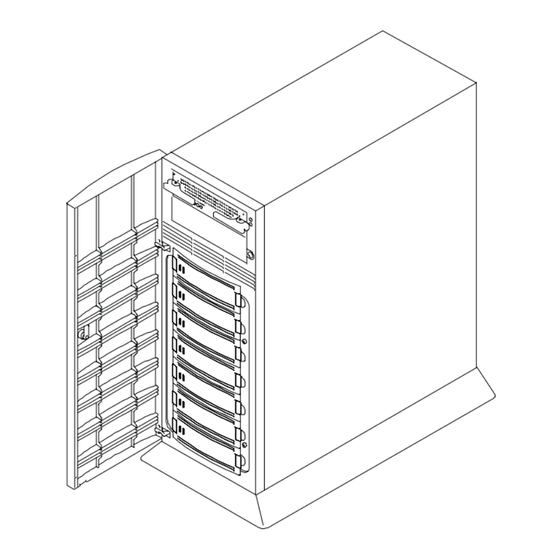
Product Overview This chapter provides an overall description of the RAID Array 3000 storage subsystem and its components. A list of technical and environmental specifications is located at the end of the chapter. NOTE This guide is the Hardware User’s Guide. For con- figuration information, refer to the Getting Started RAID Array 3000 for Windows NT –... - Page 16 RAID Array 3000 Storage Subsystem The RAID Array 3000 pedestal enclosure and its associated options are listed and described in Table 1–1. Figure 1–1 shows the pedestal with a full comple- ment of drives (optional) for completeness. Figure 1–1 RAID Array 3000 Pedestal Enclosure (Drives Optional)
-
Page 17: Raid Array 3000 Part Numbers And Model Descriptions
Chapter 1. Product Overview Table 1–1 Pedestal RAID Array 3000 Part Numbers and Model Descriptions DIGITAL Part No. Item Description DS-SWXRA-GA RA3000 pedestal subsystem with one controller, 120 V. Includes: Seven-slot pedestal for wide UltraSCSI SBBs, one HSZ22 two-channel controller with 16 MB cache, Environmental Monitor Unit (EMU), two 204 watt power supplies with fans, five meter host SCSI cable (BN37A), BN38E-OB adapter, one 120- volt Un-interruptable power supply (UPS), and North American... -
Page 18: Pedestal Features
RAID Array 3000 Storage Subsystem Pedestal Features The major features of the pedestal are: • Two differential 16-bit UltraSCSI host buses • Seven 3½-inch disk drive SBB slots • One dual-channel RAID array controller • Second controller option for redundancy •... -
Page 19: Pedestal Front Panel Major Components
Chapter 1. Product Overview Figure 1–2 Pedestal Front Panel Major Components Figure 1–3 Pedestal Rear Panel Power Supplies EK–SMCPO–UG. A01 1–5... -
Page 20: Pedestal Components
RAID Array 3000 Storage Subsystem Pedestal Components The major components in the pedestal subsystem include: • Dual-channel RAID array controller • Two 16-bit single-ended split SCSI buses • Environmental Monitor Unit (EMU) • Two universal 50/60 Hz, 120 or 240 Vac power supplies •... -
Page 21: Pedestal Power Supplies
Chapter 1. Product Overview • Per LUN write cache/write back selection • Configuration/Maintenance via RS-232 or host SCSI channel using SWCC (StorageWorks Command Console) • Update of firmware via host channel 1.4.3 Pedestal Power Supplies The pedestal has two interchangeable, air-cooled, AC power supply modules lo- cated at the rear of the unit. -
Page 22: Environmental Monitor Unit (Emu)
RAID Array 3000 Storage Subsystem 1.4.5 Environmental Monitor Unit (EMU) The EMU is an internal circuit board that monitors the operation of the pedestal. The EMU monitors power supply voltages, fans, temperatures which are reported to the user, and controls (turns on and off) the audible alarm and status LED on the front panel. -
Page 23: Ultrascsi Bus
Chapter 1. Product Overview Figure 1–5 Pedestal Rear Panel Components Exte rna l H ost #0 H o st #1 Fa ult U PS C on tro lle r (Top) C on tro ller (B ottom ) 3 0 00 -2 3A 1.4.6 UltraSCSI Buses The pedestal contains two, 16-bit, single-ended, wide UltraSCSI buses (factory- configured as a split bus) that connects the controller(s) to the disk drives. - Page 24 RAID Array 3000 Storage Subsystem Figure 1–6 UltraSCSI Bus Port and Default SCSI ID Assignments ID 8 ID 9 ID 10 ID 11 ID 8 D evice ID 9 P ort 0 D evice P ort 1 ID 10 Top C o ntroller...
-
Page 25: Ultrascsi Bus Configuration Switch
Chapter 1. Product Overview Figure 1–7 UltraSCSI Bus Configuration Switch 3000 -3 8 Figure 1–8 Slot Locations and SCSI ID Addresses C ontroller S LO T 0 ID = 8 S LO T 1 D evic e P ort 0 S LO T 2 S LO T 3 S LO T 4... -
Page 26: Specifications
RAID Array 3000 Storage Subsystem 1.5 Specifications Table 1–2 Pedestal Technical Specifications Technical Specifications Item Description Cabinet Pedestal with seven (7) disk SBB slots Expansion pedestal with an additional 7 slots Controller HSZ22 Controller cache 16 MB standard Upgrades to 128 MB for a two controller pair... -
Page 27: Pedestal Physical And Power Specifications
Chapter 1. Product Overview Table 1–3 Pedestal Physical and Power Specifications Physical Specifications Item Dimension Height 564 mm Width 254 mm Depth 494 mm Rear Clearance (air exhaust) 305 mm Front Clearance (door opening) 305 mm Weight (no devices) 19.5 kg Power Specifications Item Rating... -
Page 29: Raid Array Controller
RAID Array Controller This chapter describes the major features and characteristics of the RAID array control- ler in the RAID Array 3000 subsystem. The number of devices supported by the control- ler may be limited by the enclosure. Controller Overview The RAID Array controller provides high performance, high-availability access to SCSI disk array subsystems along a UltraSCSI/Wide SCSI bus. -
Page 30: Controller Features
RAID Array 3000 Pedestal Enclosure There are two configurations for redundant pairs of controllers: Active/Active Failover mode and Active/Passive Failover mode. In Active/Active Failover, each controller in the redundant pair has one active SCSI host port and one pas- sive SCSI host port. Redundancy Groups (Virtual LUNS) can be mapped only to one active host port and are not accessible from the passive port or the other controller (i.e. -
Page 31: Units Created From Storagesets, Partitions, And Disk Drives
Chapter 2. RAID Array Controller From the pedestal’s perspective, the controller receives the I/O requests from the host and directs them to the devices in the pedestal. Since the controller proc- esses all the I/O requests, it eliminates the host-based processing that is typically associated with reading and writing data to multiple storage devices. -
Page 32: Controller Specifications
RAID Array 3000 Pedestal Enclosure • Stripesets (RAID 0) combine disk drives in serial to increase transfer or re- quests rates • Mirrorsets (RAID 1) combine disk drives in parallel to provide a highly reli- able storage unit • RAID 4 provides striping with a fixed parity drive •... - Page 33 Chapter 2. RAID Array Controller Table 2–1 Controller Specifications (Continued) Item Specifications Disk Warm Spare (not spinning) Yes, global warm spare Redundant Power Supplies Redundant Controllers Controller Failover Yes, automatic Controller Hot Spare Yes (Active-Passive mode) Controller Hot Swap Cluster Support Yes, Single (SCSI) bus cluster Maximum number of units presented to host...
-
Page 34: Controller Reset And Led Indicators
RAID Array 3000 Pedestal Enclosure Controller Reset and LED Indicators Figure 2–3 illustrates the front panel of the controller. All LEDs are numbered from left to right. The reset button (LED 0) flashes green about once every sec- ond (heartbeat) to indicate that the controller is operating normally. LEDs 1 through 4-display host and disk channel activity (amber). -
Page 35: Flexible Raid Set Configuration
Chapter 2. RAID Array Controller Figure 2–3 Controller Front Panel Flexible RAID Set Configuration In addition to its flexible hardware design, the controller’s firmware offers the user the flexibility to configure RAID sets in several different ways: • RAID sets can comprise drives from any drive channel and SCSI ID. •... -
Page 36: Performance Enhancements
RAID Array 3000 Pedestal Enclosure • Each RAID set can be partitioned into smaller redundancy groups. • The controller’s host LUN Mapping feature makes it possible to map RAID sets differently to each host port. You make the same redundancy group ap- pear on different LUNs to different hosts, or make a redundancy group visi- ble to one host but not to another. - Page 37 Chapter 2. RAID Array Controller The controller uses several techniques to streamline write operations and signifi- cantly improve performance. All the techniques use the controller’s on-board cache, which can contain up to 64 MB of memory in the form of standard 72-pin, 60-nanosecond SIMMs.
-
Page 38: Raid Levels Supported
RAID Array 3000 Pedestal Enclosure RAID Levels Supported The RAID Array 3000 controller supports the following RAID levels: Table 2–3 RAID Levels Supported RAID Level Description Striping without parity Mirroring Striping and mirroring Striping with fixed parity drive Striping with floating parity drive JBOD “Just a Bunch of Drives”... -
Page 39: Raid 0
Chapter 2. RAID Array Controller 2.6.1 RAID 0 RAID 0 breaks up data into smaller chunks and writes each chunk to a different drive in the array. The size of each chunk is determined by the controller’s chunk size parameter, which you set in the course of creating a RAID set. The advantage of RAID 0 is its high bandwidth. -
Page 40: Raid 0 Write
RAID Array 3000 Pedestal Enclosure Figure 2–4 RAID 0 Write 2–12 EK–SMCPO–UG. A01... -
Page 41: Raid 1
Chapter 2. RAID Array Controller 2.6.2 RAID 1 RAID 1 (also known as mirroring or shadowing) takes data sent by the host and duplicates it on all the drives in an array. The result is a high degree of data availability, since you can lose all but one drive in the array and still have full access to your data. -
Page 42: Raid 0+1 Example
RAID Array 3000 Pedestal Enclosure Figure 2–6 Diagram of RAID 0+1 Write In the event of a drive failure, a RAID 0+1 array will enter degraded mode and continue to operate by substituting the failed drive with its mirror. When the controller creates a RAID 0+1 set, it first sorts the drives by channel number and SCSI ID. -
Page 43: Diagram Of A Raid 4 Write
Chapter 2. RAID Array Controller 2.6.4 RAID 4 RAID 4 breaks up host data into chunks, calculates parity by performing an ex- clusive-or on the chunks, and then writes the chunks to all but one drive in the array and the parity data to the last drive. When the host requests data from the disk drives, the controller retrieves the chunks containing the addressed data, re- constitutes the data from the chunks, and passes the data to the host. -
Page 44: Raid 5
RAID Array 3000 Pedestal Enclosure In the event of a single drive failure, a RAID 4 array will continue to operate in degraded mode. If the failed drive is a data drive, writes will continue as normal, except no data will be written to the failed drive. Reads will reconstruct the data on the failed drive by performing an exclusive-or operation on the remaining data in the stripe and the parity for that stripe. -
Page 45: Diagram Of A Raid 5 Write
Chapter 2. RAID Array Controller Figure 2–8 Diagram of a RAID 5 Write RAID 5 handles drive failures in the same manner as RAID 4, except the parity is different for each stripe. The controller either uses the parity information on a stripe to reconstruct its data or simply reads the data as normal, depending on the location of the stripe’s parity drive. -
Page 46: Jbod
RAID Array 3000 Pedestal Enclosure CAUTION RAID 5 can withstand a single failure and handle I/O activity without interruption in degraded mode until the failed drive is rebuilt. If a second drive fails while the RAID set is in degraded mode, the entire RAID set will fail. -
Page 47: System Parameters
Chapter 2. RAID Array Controller Table 2–6 System Parameters Parameter Description Password Checking Enables or disables password checking. When password checking is enabled, the controller will limit access to certain options unless the correct password is supplied. Rebuild Rate Determines how much of the controller’s processing power is to be used during rebuild operations. -
Page 48: Redundant Operation
RAID Array 3000 Pedestal Enclosure Redundant Operation When operating in a redundant configuration, the two controllers are linked such that, in case of a failure, the surviving controller can access the other controller’s cache memory and complete all operations that were in progress when the failure occurred. -
Page 49: Environmental
Chapter 2. RAID Array Controller While downloading the data, the controller responds to I/O by disconnecting (if allowed) and waiting approximately three seconds before reconnecting and pre- senting a BUSY status. The delay is to prevent host operating systems from seeing too many errors and fencing off the controller. -
Page 50: Voltage Monitoring
RAID Array 3000 Pedestal Enclosure WARNING • Slow Alarm • Normal I/O SEVERE • UltraSCSI Alarm • Flushes Cache • Enters Write-Through Mode OFFLINE • UltraSCSI Alarm • Flushes Cache • No New I/O Allowed 2.9.2 Voltage Monitoring 2.9.2.1 System Voltage The controller monitors the incoming system voltage levels and ensures they are satisfactory for controller operation. -
Page 51: Acceptable Termination Voltage Levels
Chapter 2. RAID Array Controller 2.9.2.2 Termination Voltage The controller monitors the incoming termination voltage levels and ensures they are satisfactory for controller operation. The acceptable voltage levels are shown in Table 2–9. Table 2–9 Acceptable Termination Voltage Levels State Range Action Normal... -
Page 52: Temperature Monitoring
RAID Array 3000 Pedestal Enclosure 2.9.3 Temperature Monitoring 2.9.3.1 External Temperature The controller monitors the external operating temperature and ensures they are satisfactory for controller operation. The acceptable temperature levels are shown in the following table. Table 2–11 Acceptable External Temperature Voltage Levels State Temperature Action... -
Page 53: Maintenance
Maintenance This chapter describes how to interpret the status of the LEDs on the pedestal and use them as a troubleshooting aid during a pedestal malfunction. Both the pedestal LEDs and the LEDs on the major components are covered. The chapter also describes how to replace a Field Replaceable Unit (FRU) and how to reconfigure the SCSI bus. -
Page 54: Pedestal Status And Power Leds
RAID Array 3000 Pedestal Enclosure Pedestal Status and power LEDs The pedestal is equipped with two front panel LEDs (see Figure 3–1) that moni- tor the following error conditions: • A power supply fan that is not operating • An over-temperature condition •... -
Page 55: Controller Leds
Chapter 3. Maintenance Table 3–1 Disk Drive SBB Status LEDs Activity LED Fault LED Indication Drive is operating properly. Drive is inactive and operating normally. There is no fault. Fault status: drive is defective. Recommend that you replace the device. Fault status: drive is inactive and not spinning. -
Page 56: Emu Error Reporting
RAID Array 3000 Pedestal Enclosure EMU Error Reporting The primary function of the EMU is to detect and report conditions that can cause the pedestal to malfunction and to report malfunctions. To accomplish this the EMU constantly monitors the following pedestal signals: •... -
Page 57: Replacing Components (Fru's)
Chapter 3. Maintenance Replacing Components (FRU's) This section describes how to replace an FRU in the RAID Array 3000 pedestal. The information is divided into the following subsections: • Removing the pedestal door • Replacing an SBB • Replacing a power supply •... -
Page 58: Replacing An Sbb
RAID Array 3000 Pedestal Enclosure 3.6.2 Replacing an SBB There are two methods for replacing a disk drive SBB with an identical SBB: • Hot swap – This method requires that the SCSI controller support removing and installing SBBs while the bus is active. Hot swap is supported by the RAID Array 3000 controller •... -
Page 59: Replacing A Power Supply
Chapter 3. Maintenance Figure 3–4 Replacing an SBB 3.6.3 Replacing a Power Supply You can replace a power supply without affecting pedestal operation using the following procedure: CAUTION When you remove a power supply, the airflow through the SBBs is interrupted. Always install the replacement power supply as quickly as possible to prevent overheating. -
Page 60: Replacing A Power Supply
RAID Array 3000 Pedestal Enclosure Figure 3–5 Replacing a Power Supply 3–8 EK–SMCPO–UG. A01... -
Page 61: Replacing The Raid Array Controller
Chapter 3. Maintenance 3.6.4 Replacing the RAID Array Controller Perform the following procedure to replace the RAID Array controller (see Fig- ure 3–6): 1. Grip the two locking latches on the front panel of the controller and pull them forward until the controller disengages from its mounting slot. 2. -
Page 62: Replacing The Emu Board
RAID Array 3000 Pedestal Enclosure 3.6.5 Replacing the EMU Board WARNING Only qualified service personnel should replace the EMU . Dangerous voltages are exposed when the pedestal side panel is removed. Always power off the pedestal and remove the power cords be- fore replacing the EMU. - Page 63 Chapter 3. Maintenance Figure 3–7 Remove Nuts from UPS and External Fault Connectors 3 0 00 -4 9 10. Align the connectors on the replacement EMU with the connector holes on the rear panel and replace the mounting studs to secure the board (do not over-tighten).
-
Page 64: Replacing The Ups
RAID Array 3000 Pedestal Enclosure 3.6.14 Replacing the UPS Proceed as follows to replace the UPS: 1. Ensure the UPS power switch is set to off. 2. Disconnect the pedestal power cord from the UPS. 3. Disconnect the UPS power cord from the wall outlet. 4. -
Page 65: Reconfiguring The Scsi Bus
Chapter 3. Maintenance Table 3–2 SCSI Bus Length and External Cables Rate Bus Length Longest DIGITAL Cable Speed MT/s MB/s Meters Feet Number Meters Feet Fast BN21K-23 BN21L-23 The SCSI bus in your pedestal is factory-configured as a split bus. One bus is designated bus D0 and the other as bus D1. - Page 66 RAID Array 3000 Pedestal Enclosure The SCSI bus configuration switch selects the eight (0 – 7) SCSI bus configura- tions in the pedestal. Each bus configuration determines the slot device addresses (0 – 6) for both 8-bit and 16-bit devices. The pedestal is configured at the factory for split-bus operation (configuration switch set to “6”).
-
Page 67: Remove Screw And Panel
Chapter 3. Maintenance NOTE To decrease the configuration number: Press the upper switch to step the address down one ad- dress at a time (decrement) until the desired con- figuration number is displayed. To increase the configuration number: Press the lower switch to step the address up one address at a time (increment) until the desired configuration number is displayed. -
Page 68: Location Of Scsi Bus Configuration Switch
RAID Array 3000 Pedestal Enclosure Figure 3–9 Location of SCSI Bus Configuration Switch 3 00 0 -3 8 Figure 3–10 Configuration Switch NOTE Reconfiguring the bus also involves cable and bus terminator changes. Chapter 4 of this guide de- scribes in detail how to reconfigure the bus. 3–16 EK–SMCPO–UG. -
Page 69: Replacing The Controller Memory Cache Modules
Chapter 3. Maintenance Replacing the Controller Memory Cache Modules The two memory cache modules in the RAID controller are replaced by remov- ing the controller from the pedestal to gain access to the modules. Then, place the controller on a flat working surface and proceed as follows: CAUTION To prevent an electrical discharge from damaging the SIMMs, always wear an ESD wrist strap con-... -
Page 70: Release Locking Clips
RAID Array 3000 Pedestal Enclosure Figure 3–12 Release Locking Clips Figure 3–13 Remove Installed SIMM Modules CAUTION Ensure the “side 1” side of the two replacement SIMMs is facing toward you when installing the modules in the following step. 3–18 EK–SMCPO–UG. -
Page 71: Install Replacement Modules
Chapter 3. Maintenance 5. Installed the two replacement memory modules by aligning the module and con- nector pins (check alignment guide in center of module) and gently pivot the mod- ule the main controller board until it snaps into place (see Figures 3–14 and 3–15). 6. -
Page 72: Pivot Module Down To Secure
RAID Array 3000 Pedestal Enclosure Figure 3–15 Pivot Module Down to Secure 3–20 EK–SMCPO–UG. A01... -
Page 73: Expansion Pedestal Option
Expansion Pedestal Option This chapter describes the major features of the Expansion Pedestal Option and how to connect the option to your RAID Array 3000-storage subsystem. Product Description The StorageWorks pedestal expansion option (Figure 4–1) is designed to expand the storage capacity of the RAID Array 3000 subsystem. When connected to the RAID Array 3000 base pedestal, the expansion option contains the basic compo- nents required to create a dual-pedestal storage array with a 16-bit, single-ended Ultra-SCSI bus. -
Page 74: Expansion Pedestal Cabinet
RAID Array 3000 Expansion Pedestal Expansion Pedestal Cabinet The expansion pedestal cabinet is a modular free-standing storage cabinet that is completely self contained with dual fan-cooled power supplies, an internal Ul- traSCSI single-ended extender module, and an internal EMU circuit board. The cabinet dimensions are the same as the subsystem base pedestal which houses the controller and is normally installed within one meter of the base cabinet to facili- tate the cable connections between the two units. -
Page 75: Expansion Pedestal Slot Locations And Id Addresses
Chapter 4. Expansion Pedestal Option Figure 4–2 Expansion Pedestal Slot Locations and ID Addresses ID = 8 S L O T 0 S L O T 1 S L O T 2 S L O T 3 S L O T 4 S L O T 5 S L O T 6 ID = 1 4... -
Page 76: Expansion Pedestal Components
RAID Array 3000 Expansion Pedestal Figure 4–3 Rear Panel Power Supplies Expansion Pedestal Components The expansion pedestal contains a 16-bit, wide/differential UltraSCSI bus, an Environmental Monitor Unit (EMU), a SCSI bus extender module, and two uni- versal 50/60 Hz, 100 – 240 Vac fan-cooled power supplies. The single-ended UltraSCSI bus is factory-configured as one continuous bus that runs along the backplane between the disk drive connectors and the internal ca- bles. -
Page 77: Reconfiguring Base Pedestal Ultrascsi Bus
Chapter 4. Expansion Pedestal Option The EMU (Figure 4–4) is an internal circuit board, which monitors the operation of the pedestal. The EMU monitors power supply voltages, fans, temperatures that are reported to the user, and controls (turns on and off) the audible alarm and status LED on the front panel of the pedestal. - Page 78 RAID Array 3000 Expansion Pedestal The RAID Array 3000 base pedestal is factory-configured for split-bus operation. You must reconfigure the bus in the base subsystem from split-bus to a “through- bus” configuration prior to connecting the expansion cabinet to the base subsys- tem.
-
Page 79: Remove Side Cover From Base Pedestal
Chapter 4. Expansion Pedestal Option Figure 4–5 Remove Side Cover from Base Pedestal 8. Remove the bus terminator from backplane connector J11 (Figure 4–6). Figure 4–6 Remove SCSI Bus Terminator R e m o v e Te rm in ato r 3000-40 9. -
Page 80: Disconnect Scsi Cable
RAID Array 3000 Expansion Pedestal Figure 4–7 Disconnect SCSI Cable R em ove SC S I C a ble 3000- 41 10. Connect jumper cable 17-04166-03 between the backplane connector J11 and the backplane connector J16 (see Figure 4–8). Figure 4–8 Connect SCSI Jumper C onnect Jum pe r C able 3000- 42 4–8... -
Page 81: Remove Connector Knockout Plate
Chapter 4. Expansion Pedestal Option 11. Remove the “knock-out” plate located above the D1 OUT label on the rear panel of the base pedestal (see Figure 4–9). Figure 4–9 Remove Connector Knockout Plate R em ove Kn ockou t from D 1 O ut 3 0 0 0 -4 5 12. -
Page 82: Connect Scsi Cable
RAID Array 3000 Expansion Pedestal Figure 4–10 Connect SCSI Cable C o n n e c t S C S I C a b le 30 00 -43 13. Set the bus configuration switch to “7” (see Figures 4–11 and 4–12). Figure 4–13 shows the reconfigured SCSI bus addresses of the expanded subsystem. -
Page 83: Configuration Switch
Chapter 4. Expansion Pedestal Option Figure 4–12 Configuration Switch Figure 4–13 Reconfigured SCSI Bus Addresses EK–SMCPO–UG. A01 4–11... -
Page 84: Connect Scsi Cable Between Pedestals
RAID Array 3000 Expansion Pedestal 14. Reinstall the side panel on the base pedestal. 15. Connect the HD68-to-HD68 SCSI cable from the D1 OUT connector on the base pedestal to the D1 IN connector on the rear of the expansion pedestal as shown in Figure 4–14. -
Page 85: Power Cable Connections
Chapter 4. Expansion Pedestal Option Figure 4–15 Power Cable Connections U P S B as e P e d e stal C on n ec to r P o w er Ex pa nsio n P e de sta l P o w e r P o w e r U PS... -
Page 86: Transfer Drives From Base To Expansion Pedestal
RAID Array 3000 Expansion Pedestal Figure 4–16 Transfer Drives from Base to Expansion Pedestal ID = 8 ID = 8 ID = 9 ID = 9 ID = 10 ID = 10 ID = 11 ID = 11 ID = 8 ID = 12 ID = 9 ID = 13... -
Page 87: Second Controller Option
Second Controller Option This chapter describes how to install a second RAID controller in the pedestal. The sec- ond controller provides a fail/safe feature to protect your data in case of a primary con- troller malfunction. The redundant controller is installed directly below the primary (top) controller. -
Page 88: Installation Procedure
RAID Array 3000 Pedestal Enclosure Figure 5–1 Second Controller Slot Location S econ d C ontrolle r S lot 3000-48 Installation Procedure CAUTION To prevent an electrical discharge from damaging the SIMMs, always wear an ESD wrist strap con- nected to a suitable ground when handling the memory modules. -
Page 89: Insert Module Into Simm Connector
Chapter 5. Second Controller Option 5. Perform an inventory of the items in the second controller kit. The kit should contain the following: • RAID Array 3000 controller • memory SIMMs • Model label • Warranty Card 6. Install two of the SIMM modules into the second controller (make sure all modules are of the same type) by aligning the connector pins and inserting the modules into the SIMM module connectors as shown in Figure 5–2. -
Page 90: Pivot Module Down To Seat
RAID Array 3000 Pedestal Enclosure Figure 5–3 Pivot Module Down to Seat 8. Remove the existing controller (see Figure 5–4) and install the third module into the empty SIMM connector using the same procedure described in step Figure 5–4 Remove Controller from Top Slot 5–4 EK–SMCPO–UG. - Page 91 Chapter 5. Second Controller Option 9. Replace the existing controller into the top controller slot in the pedestal and seat it into place by pushing forward on the side quick-disconnect handles. Make sure the guides on each side of the controller align with the guides in the slot.
- Page 93 Manual Order Number: EK–SMCPO–UG. A01 RAID Array 3000 Storage Subsystem Hardware User's Guide Digital is committed to providing the best possible products and services. Since our manuals are important components of our products, we value your comments, corrections, and suggestions for improvements.
Need help?
Do you have a question about the RAID Array 3000 storage subsystem and is the answer not in the manual?
Questions and answers