Table of Contents
Advertisement
Advertisement
Table of Contents

Subscribe to Our Youtube Channel
Related Manuals for Nexus NX Start Pack 4

Summary of Contents for Nexus NX Start Pack 4
- Page 1 NX Start Pack 4 Installation and Operation Manual English...
- Page 2 English Start pack 4...
- Page 3 English Start pack 4 Edition: April 2007...
-
Page 4: Table Of Contents
Correct location of transducer ..................11 2.4.2 Installing the through hull fittings .................13 Electrical Installation .......................14 Connection to other Nexus systems..................15 Pairing procedure of wind transducer ...................15 Re-initialization of the wind transducer.................16 Maintenance!..........................16 Change transducer or WSI-box / Release the pairng ............16 First start ..........................18... - Page 5 12.8.3 Velocity Made Good (VMG) ..................30 12.8.4 Boat speed........................30 12.8.5 Start up mode ......................30 12.9 More functions in a Nexus Network...................31 12.9.1 Count down display .....................31 12.9.2 Geographic Wind direction (TWD)................31 Calibration setting up the Sea Data instrument ..............32 13.1 Calibration of speed C10....................32...
-
Page 6: Part Specification
Connection back cover Silicon paste tube Plastic cable strap Inter-connection cable, 0,3 m (1 ft ) Nexus Network cable, 8 m (26 ft) Cable protectors, 0,25 mm (0.1 inch) Cable protectors, 0,75 mm (0.3 inch) 3m red power cable 3m black power cable... - Page 7 English Start pack 4 NX Sea Data - Instrument - Installation and Operation Manual English...
-
Page 8: Installation
English Start pack 4 Installation • The installation includes 6 major steps: 1. Read the installation and operation manual. 2. Plan where to install the WSI-box, transducers and instruments. 3. Run the cables. 4. Install the WSI-box, transducers and instruments. 5. -
Page 9: Installing The Instrument
Run the Nexus Network cable from the WSI- box to the instrument. • If you want to cut the Nexus Network cable to length, disconnect 4-pole jack plug and cut the cable. Peel off about 35 mm (1.4") of the cable insulation. -
Page 10: Installing The Wsi-Box
Drill the 3 screw holes using a 2.8 mm (0.11") drill. Mount the WSI-box using the 3 mounting screws. Apply silicon paste on the screw terminal. Connect the 8 m Nexus Network cable supplied with cable protectors to the WSI-box on pins 13, 14, 15, and 16. -
Page 11: Mounting The Wind Transducer Step By Step
English Start pack 4 2.3.4 Mounting the wind transducer step by step 1. Mark the mounting holes using 2. Drill the three mounting holes using a 3,2mm drill the bracket as an template 3. Mount the bracket with the three 4. -
Page 12: Installing The Log And Depth Transducers
English Start pack 4 Installing the Log and depth transducers 2.4.1 Correct location of transducer Generally the transducers should be placed as far forward as possible along the waterline length and close to the centreline. The depth transducer can be mounted on the opposite side from the speed transducer. If the transducers are mounted on the center line of the boat, the depth transducer should be mounted about 40cm in front of the speed transducer. - Page 13 English Start pack 4 Sailboats with a fin keel must have the transducer located at least 25 cm but not more than 75 cm in front of the keel. It should be placed no more than 10 cm off the centreline. On sailboats with a pronounced “V”...
-
Page 14: Installing The Through Hull Fittings
English Start pack 4 2.4.2 Installing the through hull fittings Use a 43 mm (1 11/16”) hole cutter to cut through the hull. (See section 3 for correct location). Apply the polyurethane sealing compound on the outer flange of the through-hull fitting and tighten the nut on the inside by hand. -
Page 15: Electrical Installation
English Start pack 4 Electrical Installation... -
Page 16: Connection To Other Nexus Systems
Mount the connection back cover with the screw. Connection to other Nexus systems A NX system is fully compatible with other Nexus Network system such as NX2. If you want to connect the NX system to a NX2 system, you have to move the connection of the log and depth transducers to the WSI box. -
Page 17: Re-Initialization Of The Wind Transducer
Start pack 4 If the batter lid is open, you may see the LED. The built in LED will flash 2 times then lit for 2s, before it is turned off. Your Nexus system is now ready for use. If the pairing of some reason did not work, the LED will flash a third time. - Page 18 English Start pack 4 Press the PLUS button until the text C15 is showed Note the value for C15. Press SET (short) and enter the value 99.9 using MINUS, PLUS and PAGE. Press SET. The WSI-boxen has now released the pairing and you can now enter the value you noted under point 3 again Press PAGE followed by SET to exit the setting mode B From a NX Wind instrument...
-
Page 19: First Start
This will give the instrument a logical ID number that belongs to your specific Nexus Network. Press SET, on each installed instrument, one at the time. Always wait for the text ‘Init OK’... -
Page 20: How To Use The Push-Buttons Of The Sea Data
English Start pack 4 How to use the push-buttons of the Sea Data MAIN PAGE MAIN FUNCTION FUNCTION CLEAR MINUS PAGE PLUS Clear trip log, Move to the next Change main Move to the Set or edit alarm cancel alarms sub-function. -
Page 21: Instrument Backlight
English Start pack 4 Instrument backlight The back light may be switched on at the Sea Data or wind instrument. 1. Press and hold PAGE 2 sec 2. Select backlight level with PLUS 3. Set the light level with SET Function overview of the Sea Data The functions in the Sea Data instrument are divided into 2 pages: SPEED and DEPTH. -
Page 22: Speed Functions
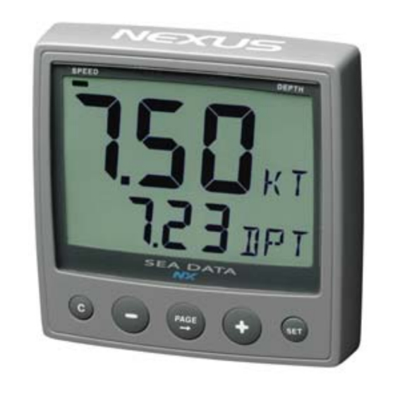
English Start pack 4 10 SPEED functions The Sea Data instruments SPEED page is indicated by the LCD marker at top of the display. You can easily combine this main function with any sub function (See 9). SPEED main-function Boat speed through the water Unit available in knots (KT), km/h (Kh) or miles/h (Mh) SPEED sub-functions Both water speed and water temperature is measured from the... -
Page 23: Maximum Speed (Max)
English Start pack 4 MAXIMUM SPEED (MAX) Maximum speed since power on, or from reset of start timer To reset, press CLEAR DEPTH (unit/DPT) Depth reading can be set to show distance from the water surface or from the keel. Unit in meters (m), feet (FT) or fathoms (FA) The text alternates between the selected (unit) and (DPT). -
Page 24: Depth Functions
English Start pack 4 11 DEPTH functions DEPTH main-function The actual depth between the boats keel or the water surface. Units in meters (m), feet (FT) or fathoms (FA) Preference is set by the user. DEPTH sub-functions LIGHT CONTROL Set light level for all instruments, LOW, MID, MAX or OFF. SHALLOW ALARM (SHA) Aaudible and visual alarm is activated if the actual depth becomes less than the pre-set value. -
Page 25: Apparent Wind Angle (Twa)
English Start pack 4 11.1.2 APPARENT WIND ANGLE (TWA) Displays the apparent wind angle. 11.1.3 TRUE WIND SPEED TWS This function requires a log transducer. Displayed in m/s (m/s), knots (KTS) or Beaufort (BF). (See 12.5, C52).The text alternates between (TWS) and the selected (unit) 11.1.4 APPARENT WIND SPEED (AWS) Units displayed in m/s (m/s), knots (KTS) or Beaufort (BF), (see... -
Page 26: Silencing An Alarm
English Start pack 4 11.5 Silencing an alarm To silence a triggered alarm that sounds and flashes, press ANY button. The sound is silenced and the flashing stops. The alarm is only triggered again if the selected depth value is exceeded (shallower or deeper) by 2 m (6 feet). -
Page 27: Customise Your Display
English Start pack 4 12 Customise your display All sub-functions are organised in a list under the main-function. The first location in the sub-function list is an empty display. You can have your favourite sub-function moved in the same sub-function list, or copied and locked to any other page. 12.1 Move and lock a sub-function Example: In SPEED page, move and lock the sub-function depth (DPT) to the top of the sub-function list. -
Page 28: How To Use The Push Buttons Of The Wind Instrument
English Start pack 4 12.5 How to use the push buttons of the Wind instrument MAIN APPARENT FUNCTION WIND ANGLE INFOTEXT TRUE WIND ANGLE SUB- FUNCTION CLEAR MINUS PAGE PLUS A press on A press on A press on A press on PLUS A press on SET CLEAR, clear MINUS moves to... -
Page 29: Main Function
The text [APP = apparent] or [TRU = true] is displayed when PAGE is pressed. For closed hauled function, se setting C20. TWD 360 When a compass or GPS is connected to the Nexus Network, the text TWD 360 display shows True Wind Direction (geographical). To select Compass, See 14.1.7... - Page 30 English Start pack 4 WIND...
-
Page 31: Sub-Functions
The water speed information from the log transducer needed. speed information can be taken from the log transducer or from Nexus Network. VMG = 0.0 knots when the true Wind angle is perpendicular to the boat. 12.8.4 Boat speed The text [BSP] (Boat Speed) and its value is displayed below. -
Page 32: More Functions In A Nexus Network
English Start pack 4 12.9 More functions in a Nexus Network When connected in the Nexus Network, the following additional functions will be added: Count down display (race timer) TWD (True Wind Direction) Use GPS as reference for TWS, TWA and TWD instead of water speed. -
Page 33: Calibration Setting Up The Sea Data Instrument
Start pack 4 13 Calibration setting up the Sea Data instrument To get the most out of your Nexus instrument, it is important to carefully calibrate the instrument. The calibration values are stored in a memory and will keep the values even if the instrument is un powered for more than 1o years. -
Page 34: Damping Of Speed, C13 (Sea)
English Start pack 4 If you suspect a current in the water, drive the boat in both directions and divide trip counter distance by 2. 13.1.4 Damping of Speed, C13 (SEA) Damping of indicated boat speed through the water. Controls the response time of speed changes. -
Page 35: Adjustment Of Temp Reading,C17 (0°C Tmp)
English Start pack 4 13.1.8 Adjustment of Temp reading,C17 (0°C TMP) Value to adjust the temperature. To add, use underlining character ( _ ) ahead of the digit ( _1 TMP). To subtract, use minus character ( - ) ahead of the digit (-1 TMP). 13.1.9 Unit for Air Pressure, C18 (Unit hPA) Future function. -
Page 36: Calibration And Setup Of The Wind Instrument
Start pack 4 14 Calibration and setup of the Wind instrument To get the most out of your Nexus instrument, it is important to carefully calibrate the instrument. The calibration values are stored in a non volatile memory. To access calibration page, press and hold SET more than 2 seconds. -
Page 37: Calibration Of Log Transducer, C15
If the Wind is installed with WSI-box or NX2 Server where the log is already calibrated, no further calibration is needed. Calibration value for speed and distance (1.00 - 1.99) Check calibration in your Nexus log and enter the same value. 14.1.6 Reference for Speed, water or GPS, C16 Select speed reference. -
Page 38: Where Is The Wind Tx Connected, C18
English Start pack 4 Note! [COG] as reference will only operate properly when the boat is doing speed over ground. If COG is used and the boat is lying still, the TWD will show random readings. 14.1.8 Where is the wind Tx connected, [On] = Set to On if a Wind transducer is connected at the Wind instrument with a cable. -
Page 39: Wind Settings, C50
English Start pack 4 14.2 Wind Settings, C50 To return to normal PAGE, press SET when the text C50 [rET] is displayed. C51 not used! 14.2.1 Unit for Wind speed, C52 Unit for Wind speed [KTS] for (KnoTS), [M/S] for (Metres/S) and [BF] for (Beaufort). - Page 40 English Start pack 4...
-
Page 41: Maintenance And Fault Finding
All connected instrument and trancducers , including their software version numbers. • Server software version number. • Nexus Network data bus ID numbers for each instrument (displayed at power up). 15.2.1 General fault finding In most cases, the reason for faults in electronic equipment is the installation or poor connections. -
Page 42: Fault - Action
For more information, see manual for WSI box or NX2 Server. 15.2.3 Error messages The following error messages can appear on the display: ERROR 2 Nexus Network is missing, check colour coded connections ERROR 3 No data received within a given time. ERROR 10 Range error caused by bad format e.g. -
Page 43: Specifications
English Start pack 4 16 Specifications 16.1 Technical specifications Sea Data Dimensions: Sea data instrument: 113 x 113 x23 mm (4.3x4.3 inch). Instrument cable: 8 m (26 ft). Power supply: 12V DC (10-16V). The instruments are polarity protected Power consumption at 12V: Sea Data instrument: 0,08W with maximum lighting 0,8W. - Page 44 English Start pack 4 CE approval The products conforms to the EMC requirements for immunity and emission according to EN 50 08-1.
-
Page 45: Waranty
English Start pack 4 17 Waranty... - Page 46 English Start pack 4...
- Page 47 English Start pack 4...
- Page 48 English Start pack 4 Copyright ©: Nexus Marine AB Kuskvägen 4, 191 62 Sollentuna, Sweden Tel: +46 -(0) 8 – 506 939 00. Fax: +46 -(0) 8 -506 939 01 www.nexusmarine.se...
Need help?
Do you have a question about the NX Start Pack 4 and is the answer not in the manual?
Questions and answers