Table of Contents
Advertisement
Quick Links
Pub. 43004-013E
G A I - T R O N I C S ® C O R P O R A T I O N
A H U B B E L L C O M P A N Y
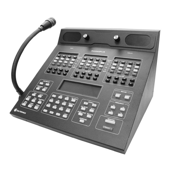
CommandPLUS Series
Desktop Console
Installation and Service Manual
GAI-Tronics Corporation P.O. Box 1060, Reading, PA 19607-1060 USA
610-777-1374
800-492-1212
Fax: 610-796-5954
V
.
-
.
ISIT WWW
GAI
TRONICS
COM FOR PRODUCT LITERATURE AND MANUALS
Advertisement
Table of Contents

Summary of Contents for GAI-Tronics CommandPLUS Series
- Page 1 G A I - T R O N I C S ® C O R P O R A T I O N A H U B B E L L C O M P A N Y CommandPLUS Series Desktop Console Installation and Service Manual GAI-Tronics Corporation P.O. Box 1060, Reading, PA 19607-1060 USA 610-777-1374 800-492-1212 Fax: 610-796-5954 ISIT WWW...
- Page 2 Buyer hereby agrees to indemnify, defend and hold GAI-Tronics harmless from and against any and all third party claims arising, in any manner, out of: (a) Buyer’s neglect of the equipment; (b) Buyer’s use of technicians not authorized by GAI-Tronics to service the equipment; or (c) Buyer’s improper use or modification of the equipment or failure to follow the operational and maintenance procedures provided with the equipment.
-
Page 3: Table Of Contents
Table of Contents FOREWORD ............................... 1 .............................. 2 COPE OF ANUAL ..............................2 OMENCLATURE ......................... 2 RDERING EPLACEMENT ARTS ............................2 ERVICE AND EPAIR CMOS I .................. 3 ANDLING OF NTEGRATED IRCUIT EVICES PLUS S ................4 EATURES OF THE OMMAND ERIES ESKTOP... - Page 4 Table of Contents CommandPLUS Series Desktop Console Installation and Service Manual Setting the Clock ............................29 Setting the Display Viewing Angle ....................... 29 Setting the Display Brightness ........................30 ............................30 ERVICE IAGNOSTICS Keyboard Diagnostics..........................31 Keyboard Test ................................31 LED Test ..................................31 Audio Diagnostic ............................
-
Page 5: Foreword
0.3). For earlier products, the REN is separately shown on the label. If this equipment [GAI-Tronics telephone] causes harm to the telephone network, the telephone company will notify you in advance that temporary discontinuance of service may be required. But if advance notice isn’t practical, the telephone company will notify the customer as soon as possible. -
Page 6: Scope Of Manual
Console. Service diagrams and printed circuit board details are a part of this service manual. The Command PLUS Series Desktop Console Operator’s Manual, 43004-016, is another publication related to the operation of the CommandPLUS Series Console. Both manuals are available on our website at www.gai-tronics.com. -
Page 7: Safe Handling Of Cmos Integrated Circuit Devices
CommandPLUS Series Desktop Console Installation and Service Manual Foreword Safe Handling of CMOS Integrated Circuit Devices Many of the integrated circuit devices used in communications equipment are of the Complementary Metal Oxide Semiconductor (CMOS) type. Because of their high open circuit impedance, CMOS integrated circuits are vulnerable to damage from static charges. -
Page 8: Features Of The Commandplus Series Desktop Console
Foreword CommandPLUS Series Desktop Console Installation and Service Manual Features of the CommandPLUS Series Desktop Console • Enhanced multi-tasking operation • Available in 4, 8, and 12-channel control. 4 and 8-channel consoles are field expandable. • Accommodates a minimum of 10 consoles per system •... -
Page 9: Model Chart
CommandPLUS Series Desktop Console Installation and Service Manual Foreword Model Chart The following is a list of the CommandPLUS Series Desktop Console models: Model Description ICP9004A CommandPLUS Series 4-Channel Desktop Console (expandable) ICP9008A CommandPLUS 8-Channel Desktop Console (expandable) ICP9012A CommandPLUS 12-Channel Desktop Console... - Page 10 Foreword CommandPLUS Series Desktop Console Installation and Service Manual The following field installation kits are available for installation in the CommandPLUS Series Desktop Console: Description XCP0010A DC Control Kit XCP0020A 16-Frequency Capable Kit (existing installation upgrade) XCP0030A 25-Pair Telco Interface Kit XCP0040A 4-Channel E&M Signaling Kit (requires CP0050 or XCP0050A)
-
Page 11: Specifications
F3 Transmit: 1350 Hz F4 Transmit: 1250 Hz Monitor: 2050 Hz Function tones are selectable via GAI-Tronics’ CARD Suite Software Application Transmit Audio Condenser microphone................ Selectable, digital steps 1 through 5 Microphone sensitivity ........... Reference 165 mV, selectable, digital steps 1 through 5 Audio out to phone line .............. - Page 12 Foreword CommandPLUS Series Desktop Console Installation and Service Manual FCC Information FCC Registration Number ..................US: ADGOT01B46053 Ringer Equivalence Number (REN)......................1 Network connection (USOC)......................RJ11 IC Information (Canada) IC Certification Number ......................8226048 A Ringer Equivalence Number (REN)......................1 Connecting method ........................
-
Page 13: Description
The CommandPLUS Series Desktop Console is a multi-channel console compatible with conventional radio systems. It uses tone remote control to interact with the base stations, but dc remote control and E&M control are available as options. The CommandPLUS Series Console allows control of up to 12 individual base stations. -
Page 14: Dc Remote Control
Description CommandPLUS Series Desktop Console Installation and Service Manual DC Remote Control DC control is a method of remote radio control. This scheme uses dc currents of differing magnitudes and polarities to command the radio to perform various tasks. The dc control currents are directly impressed upon the audio wire line connections between the console and base stations. -
Page 15: Installation
Installation General Considerations The CommandPLUS Series Desktop Console can be placed on any flat level surface (desk top) that provides the operator with full visibility of all front panel controls and indicators. Mechanical Receipt Inspection The CommandPLUS Series Desktop Console is shipped in a cardboard container with inserts. Thoroughly inspect it as soon as possible after delivery. -
Page 16: Line Connections
Installation CommandPLUS Series Desktop Console Installation and Service Manual Line Connections Line Considerations - Private Circuit If leased lines from your local telephone company are used between the console and a tone remote adapter or base station, the telephone company (Local Exchange Carrier) may request a Facility Interface Code (FIC). -
Page 17: Line Level Settings
CommandPLUS Series Desktop Console Installation and Service Manual Installation Line Level Settings The CommandPLUS Desktop Console allows the installer to adjust level settings through the on-screen diagnostics. These procedures assume that the base stations have been properly adjusted. Line Input (Receive Audio) Level Adjustment The line input level adjustment allows the receive audio of each channel to be compensated for line loses between the base station and console, ensuring optimum audio performance of the console. -
Page 18: Types Of Base Station Control
In this configuration, a single two-wire line is used to carry the control tones or dc control currents (as applicable per channel) and the transmitter audio, from the CommandPLUS Series Console to the base station. This same 2-wire line is used to return the receive audio back to the console from the base station. -
Page 19: Installation
All of the electrical connections to the console are made at the rear panel. Power to the console is furnished through a 5-pin, DIN connector, P5. The Figure 2 shows the rear view of the CommandPLUS Series Desktop Console and the locations of the various connectors. -
Page 20: Ground Cable
USOC, RJ21X Telephone Connector. Power Supply (3308-00124-00) The CommandPLUS Series Desktop Console uses an external power supply provided with the unit. This is a self-contained unit that can be positioned on the desk with the console or located at some other convenient spot. -
Page 21: Accessories
CommandPLUS Series Desktop Console Installation and Service Manual Installation Accessories XGM003A Gooseneck Microphone/ XDM003A Desk Microphone These heavy-duty microphones connect directly to the RCA connector labeled on the rear of the console. The console-adapted gooseneck microphone mounts to the right or left side of the console. If right-hand mounting is required, relocate the base mounting bracket to its other slot. -
Page 22: Xcp0140A Headset Interface Box
Installation CommandPLUS Series Desktop Console Installation and Service Manual XCP0140A Headset Interface Box The interface box allows the use of several headset accessories, such as the Startset II, Supra headband-style monaural headset, and Supra headband-style noise-canceling headset. The headset jack is assembled for mounting on the right-hand side of the console. -
Page 23: Headset/Handset Connection
CommandPLUS Series Desktop Console Installation and Service Manual Installation Headset/Handset Connection An 8-pin modular connector is provided on the rear of the console for connection of the XCP0500A Handset Assembly or XDM002A Low-End Desktop Microphone. (Use of the XDM002A Microphone for console operation is not recommended.) For proper operation, jumpers must be properly installed. -
Page 24: Xfs002A Footswitch
Installation CommandPLUS Series Desktop Console Installation and Service Manual XFS002A Footswitch This accessory, which provides both hands-free PTT and monitor functions, is provided with a cable fitted with a keyed connector containing three contacts. This connector mates with P7 on the back of the console. -
Page 25: System Jumper Table
(parallel or single console). Refer to Figure 5. The CommandPLUS Series Desktop Console is shipped with all line termination resistors in place. For parallel operation of multiple consoles, the last console on any particular line should have its 2W or 4W termination jumpers in place and any intermediate console should have the line termination jumpers removed. - Page 26 Installation CommandPLUS Series Desktop Console Installation and Service Manual The Figure 5 shows the positions on the upper portion of the CSD slave board. Figure 5. 2-Wire/4-Wire Jumper Configuration 09/07...
-
Page 27: Card Suite Programming Software
Connections The GAI-Tronics equipment must be connected to your personal computer with the programming cable, part number XAC0170A, before the programming software can be used. To make this connection, attach the cable to the COM1 or COM2 connector on the computer. - Page 28 CARD Suite Software CommandPLUS Series Desktop Console Installation and Service Manual 09/07...
-
Page 29: Console Diagnostics
Console Diagnostics Entering the Diagnostic Mode The CommandPLUS Series Console contains several internal diagnostics designed to assist in the installation and servicing of the unit. The opening menu for these diagnostics is accessed by pressing the LOCK + MODE key combination. -
Page 30: User Parameters Menu
Console Diagnostics CommandPLUS Series Desktop Console Installation and Service Manual User Parameters Menu The User Parameters menu is shown below. USER PARAMETERS 1) SIDE TONE VOLUME ADJUST 2) MIC SELECTION/SENSITIVITY 3) PRINTER ERROR <1-3> SELECT <MODE> TO EXIT MAY-12-07 12:22:19PM Figure 7. -
Page 31: Microphone Selection And Sensitivity
CommandPLUS Series Desktop Console Installation and Service Manual Console Diagnostics Microphone Selection and Sensitivity There are three available microphone ports available on the CommandPLUS. These are the internal port, desk/handset/headset port, and the gooseneck port. By default, the console is shipped with the internal port selected. -
Page 32: Printer Error Messages
Console Diagnostics CommandPLUS Series Desktop Console Installation and Service Manual Printer Error Messages The console supports the use of a serial printer to log decoded ANI information as well as access to diagnostics and other diagnostic data. If the printer is enabled through the CARD Suite software and the console detects an error, PRINTER ERROR is displayed on the lower right-hand side of the console display unless the printer error message is disabled. -
Page 33: Setting The Clock
CommandPLUS Series Desktop Console Installation and Service Manual Console Diagnostics Setting the Clock The clock can be adjusted by selecting the Set Clock and Date menu. When selected, the following display is shown. SET CLOCK/DATE HH:MM:SS PM MM-DD-YY <SCROLL> TO SELECT <MODE>... -
Page 34: Setting The Display Brightness
Console Diagnostics CommandPLUS Series Desktop Console Installation and Service Manual Setting the Display Brightness The brightness of the console’s display can be optimized for the particular location. For example, in a dim environment, the display is more easily read when it is set for a high brightness level. -
Page 35: Keyboard Diagnostics
2 to execute the LED test. Keyboard diagnostics allows the testing of all buttons and LEDs on the front panel of the CommandPLUS Series Desktop Console. These diagnostics are useful in servicing the unit should a problem occur. Press the key at any time to exit these diagnostics. -
Page 36: Audio Diagnostic
Console Diagnostics CommandPLUS Series Desktop Console Installation and Service Manual Audio Diagnostic When 2 is pressed from the Service Diagnostics Menu, you are prompted to enter a number from 1 through 5 in order to select a particular audio/communication test. These tests are described below. -
Page 37: Internal Diagnostics
CommandPLUS Series Desktop Console Installation and Service Manual Console Diagnostics Internal Diagnostics When 3 is selected from the Service Diagnostics Menu, you are prompted to enter a number from 1 through 7 to select the desired test. This test allows the optional supervisory board to be tested. The Supervisory test 1 –... -
Page 38: Start-Up Display
Boot-Up Error Code Definitions The following error codes are displayed automatically upon boot-up: Master– 00 If anything other than 00 is displayed for the master error, contact GAI-Tronics field service. Slave– 00 00 00 00 = OK 01 = Slave not present... -
Page 39: Features And Options
The normal transmit function tone follows the coded/clear function tone. 1. Up to three Console Interface Units (CIUs) can be connected to the CommandPLUS Series Desktop Console. Table 11. CIU Pin Connection... -
Page 40: Printer Interface
Features and Options CommandPLUS Series Desktop Console Installation and Service Manual Table 12. Accessory I/O – DB15 Male Connector Pin No. Pin Function Asserted State Encode control IN 4 Indicates that receive audio on CIU 4 is coded Encode control IN 3... -
Page 41: Logging Recorder Output Module
CommandPLUS Series Desktop Console Installation and Service Manual Features and Options Table 13. Connect to: CommandPLUS Description DB25 DB9 (PC) (Printer) Ground TX Data RX Data Logging Recorder Output Module This standard feature consists of an additional board that is installed in the CommandPLUS. This feature adds a logging recorder output that provides a line-level sum of the transmit mic audio, paging tones, receive audio, parallel console audio, and all signaling. -
Page 42: Dc Control Cp0010A/Xcp0010A
Features and Options CommandPLUS Series Desktop Console Installation and Service Manual DC Control CP0010A/XCP0010A This option provides standard dc control currents on a per channel basis. Its operation requires the installation of one option card for each dc-controlled channel. Installation/Relocation IMPORTANT: OBSERVE STATIC CONTROL PROCEDURES 1. - Page 43 CommandPLUS Series Desktop Console Installation and Service Manual Features and Options Figure 17. 5. Mount the XCP0010A DC Control Option CDC board to the appropriate slave board (1, 2, or 3) and channel (1, 2, 3, or 4 for each board). The CDC board must be mounted on the bottom side of the slave panel.
-
Page 44: 4-Channel E&M Control Cp0040A/Xcp0040A
The Supervisory Control option provides the ability to override parallel consoles on selected channel(s) to comply with FCC regulations. The unit mounts as a “bustle-back” on the rear panel of the console. Refer to the CommandPLUS Series Desktop Console Operator’s Manual for user instructions for the supervisory control. -
Page 45: Direct Enhanced Full Duplex Phone Interface Cp0070/Xcp0070A
Direct Enhanced Full Duplex Phone Interface CP0070/XCP0070A The Direct Enhanced Phone Interface option adds the Phone Patch and the Radio Patch features to the CommandPLUS Series Desktop Console. It provides single line telephone functionality to the console. Ring Detect Sensitivity Jumper J400 is provided to allow operation under a wide range of ring voltages. -
Page 46: 25-Pair Telco Interface Xcp0030A
The Telco Interface Kit adapts the DB25 rear panel connectors to a single 50-pin standard connector. The unit mounts on the rear panel of the CommandPLUS Series Desktop Console and plugs into the three DB25 connectors, P40 (a) (b) (c). The Model XCP0030A 25-Pair Telco Interface Kit includes the... - Page 47 CommandPLUS Series Desktop Console Installation and Service Manual Features and Options Supervisory Mounting 1. Disconnect the power from the CommandPLUS Series Desktop Console and remove all attached cables from the rear cover. 2. Mount the Telco Interface to the Supervisory unit on the rear of the console. Refer to Figure 19.
-
Page 48: Button/Elastomer Replacement (Xcp0110A)
Features and Options CommandPLUS Series Desktop Console Installation and Service Manual Table 16. Telco Interface Pin Connectors Pin Function (Pin #) Pin Function (Pin #) Pair # (Pin #) (for dc pos, neg) Pair # (Pin #) (for dc pos, neg) -
Page 49: Paging
Paging Types of Paging The CommandPLUS Series Desktop Console supports the following types of paging: DTMF, 2-Tone, Plectron 5/6-Tone, 1500, and 2805. The CARD Suite software application is used to set the parameters for these paging types. : In many applications below 800 MHz, the maximum allowable signaling time, as prescribed by FCC regulations, is 3 seconds and only signal once. -
Page 50: Group Call
Paging CommandPLUS Series Desktop Console Installation and Service Manual 4. The first digit of this number (6 in this example) corresponds to a number under the Group # heading on Table 18, and indicates which row of frequencies on Table 18 will be used for the A tone. In this example, the A tone number entered by the console operator is 4, which corresponds to 1251.4 Hz. - Page 51 CommandPLUS Series Desktop Console Installation and Service Manual Paging Table 17. Code Plans Important Note: The 1 digit indicates Chart A Group # Source for the A tone, and the 2 digit indicates Chart A Group # Source for B Tone.
- Page 52 Paging CommandPLUS Series Desktop Console Installation and Service Manual Table 18. Tone Group Frequency Chart The chart below cross-references the 2-Tone Paging Code to the frequency in Hz. Tone Group Group # 330.5 349.0 368.5 389.0 410.8 433.7 457.9 483.5 510.5...
-
Page 53: Plectron Paging
CommandPLUS Series Desktop Console Installation and Service Manual Paging Plectron Paging The Plectron paging feature requires a 4-digit prefix (capcode). Like 2-Tone paging, the capcode and code plan will determine at what frequency the paging tones will be transmitted. Plectron paging uses the Plectron Code Plan Chart (Table 19) and Plectron Tone Group/Frequency Chart (Table 20). - Page 54 Paging CommandPLUS Series Desktop Console Installation and Service Manual Table 20. Plectron Tone Group/Frequency Chart (in Hz) 3rd and 4th Digits Tone Group P1 Tone Group P2 1036 1082 1130 1180 1232 1287 1344 1403 1465 Tone Group P3 1530...
-
Page 55: 5/6-Tone Paging
CommandPLUS Series Desktop Console Installation and Service Manual Paging 5/6-Tone Paging The 5/6-tone paging type provides a method to page a series of tone bursts that can be customized based on the type of 5/6-tone paging and a 2-digit preamble. Motorola EIA 5/6-tone paging supports a programmable preamble frequency and dual addressing. - Page 56 Paging CommandPLUS Series Desktop Console Installation and Service Manual Table 22. 5/6 Tone Paging Tone Timing 5/6 Tone Type Extended Motorola BOS/ Modified 70ms Tone Bruchcal ZVEI CCIR CCIR CCIR Preamble (ms) Gap (ms) Address 1000 Tone (ms) Next 4 Tone...
-
Page 57: Troubleshooting
Troubleshooting Troubleshooting the CommandPLUS Series Desktop Console The following is a list of potential problems you may encounter and possible solutions. Problem Possible Solution There is low or no mic Check the setting of the mic and its level in the Mic Selection/Level Menu. -
Page 58: Replacement Parts List
Supervisor PCBA Replacement Kit XCP0050A ICP Lightning Protection Board CP-CLP Replacement Button/Elastomer Kit XCP0110A ICP Power Supply 3308-00124-00 ICP Power Supply with Battery Revert CP-BR-PS Internal Mic Assembly 13507-013 : For availability of all other parts, please contact the GAI-Tronics Service Department. 09/07... -
Page 59: Main Circuit Board
Main Circuit Board 09/07... - Page 60 Main Circuit Board CommandPLUS Series Desktop Console Installation and Service Manual Figure 20. ICP Main Board 69405-001...
-
Page 61: Definitions And Acronyms
Definitions and Acronyms Term Definition Carrier squelch The identifying number on the outside of the radio pager. It is related to the tone or Capcode digital code that gives the address and other information about this particular pager. Detection of a valid mobile signal is based on loss (squelch) of random channel noise. Carrier Squelch Continuous Tone Controlled Subaudible System - A means of grouping users of a... - Page 62 Notes: CommandPLUS Series Desktop Console Installation and Service Manual 08/07...
Need help?
Do you have a question about the CommandPLUS Series and is the answer not in the manual?
Questions and answers