Table of Contents
Advertisement
Quick Links
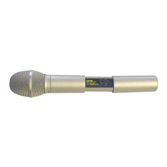
MTH300 QUICK USER GUIDE
MTH300 is a professional radio microphone especially design for broadcast/high quality
applications.
1. OPERATION
MTH300 is composed by 3 detachable parts:
1) MIC Head (available with cardioid/hypercardiod polar pattern).
2) MIC Body (the below part can be open to access "Display & Setup controls" area
(fig.1) and on the back the "Batteries holder & Infrared" area (fig. 2).
3) MIC Antenna, made with fibreglass reinforced housing and with a "Wireless power
switch" (fig. 3). "MIC Antenna" is fastened to body with 2 anvils and a micro-
connector.
1
:
Exchange head
unscrew it counter-clockwise
Fig. 1 Display & Setup controls
1.1
LED INDICATION (POWER SWITCH)
Led indication with bicolor led (red & green) on wireless power switch (fig. 3):
-
Wireless transmission status: green on/off)
-
Battery status: green steady, slowly blinking (< 25%), quickly blinking (<12%)
-
Modulation peek (if activated): red
-
Ptt status: red if active
1.2
BATTERIES
MTH300 is working with 2 AA alkaline or NiMH batteries (select correct type on setup controls).
Battery status can be checked on internal OLED display or looking to LED status on power
switch (see 1.1)
1.2.1 BATTERY SUBSTITUTION
Open MIC body: unscrew counter-clockwise the below cover to access batteries holder;
Take out below battery to release upper battery leverage;
nd
2
battery falls down and can be removed.
WISYCOM s.r.l. - Via Spin, 156 - I-36060 Romano d'Ezzelino (VI) - Italy - MTH300-eng-u03.doc
Tel. (Ph.). +39 0424 382605 - Fax +39 0424 382733 - http:// www.wisycom.com - e-mail: sales@wisycom.com
2
Fig. 2 Batteries holder and infrared
Open MIC Body:
Unscrew & slide down cover, to
acces internal setup controls and
batteries holder & infrared.
3
Wireless power switch
with programmable
LED indication
(green/red).
Fig. 3 Wireless
power switch
Advertisement
Table of Contents

Summary of Contents for WisyCom MTH300
- Page 1 Modulation peek (if activated): red Ptt status: red if active BATTERIES MTH300 is working with 2 AA alkaline or NiMH batteries (select correct type on setup controls). Battery status can be checked on internal OLED display or looking to LED status on power switch (see 1.1)
- Page 2 - RF active, top right label RF (if present RF is on) WISYCOM s.r.l. - Via Spin, 156 - I-36060 Romano d’Ezzelino (VI) - Italy - MTH300-eng-u03.doc Tel. (Ph.). +39 0424 382605 - Fax +39 0424 382733 - http:// www.wisycom.com - e-mail: sales@wisycom.com...
- Page 3 To unlock, long pressing (2 sec.) selector button again. WISYCOM s.r.l. - Via Spin, 156 - I-36060 Romano d’Ezzelino (VI) - Italy - MTH300-eng-u03.doc Tel. (Ph.). +39 0424 382605 - Fax +39 0424 382733 - http:// www.wisycom.com - e-mail: sales@wisycom.com...
- Page 4 WISYCOM s.r.l. - Via Spin, 156 - I-36060 Romano d’Ezzelino (VI) - Italy - MTH300-eng-u03.doc Tel. (Ph.). +39 0424 382605 - Fax +39 0424 382733 - http:// www.wisycom.com - e-mail: sales@wisycom.com...
Need help?
Do you have a question about the MTH300 and is the answer not in the manual?
Questions and answers