Table of Contents
Advertisement
Quick Links
Rev 1.56 June 2004
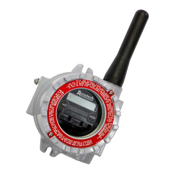
Base Radio
User Manual
_______ _____ ______ _____ _____ _____ _____ _____ ______ _____ _____ _____ _____ ______ _____ _____ _____ _____ _____ ______ _____ _____ _____ _____ _____ ___
A Division of Adaptive Instruments Corp.
577 Main Street
·
Hudson, MA 01749 U.S.A.
TEL: 800-879-6576
·
978-568-0500
FAX: 978-568-9085
Email: support@accutechinstruments.com
www.accutechinstruments.com
Advertisement
Table of Contents

Summary of Contents for Accutech WI-BR-I-XP
- Page 1 Rev 1.56 June 2004 Base Radio User Manual _______ _____ ______ _____ _____ _____ _____ _____ ______ _____ _____ _____ _____ ______ _____ _____ _____ _____ _____ ______ _____ _____ _____ _____ _____ ___ A Division of Adaptive Instruments Corp. 577 Main Street ·...
- Page 3 User Manual Base Radio Models WI-BR-I-XP, WI-BR-I-XP- MOD and WI-BR-I-XP-AO Versions 1.56 or later Important Information to the User • Changes or modifications not expressly approved by Adaptive Instruments, LLC may void the user’s authority to operate the equipment. •...
-
Page 5: Table Of Contents
Table of Contents Section 1: Introduction ____________________________________ 1 1.1: Using This Manual 1.2: About the Device 1.3: Unpacking 1.4: Software Compatibility Section 2: In a Hurry? ____________________________________ 3 Section 3: Installation _____________________________________ 4 3.1: Mechanical Installation 3.1.1: Base Radio Positioning 3.1.2: Base Radio Mounting 3.2: Electrical Installation 3.2.1: Electrical Specifications... - Page 6 Accutech Wireless Base Radio User Manual Table of Figures 3.1: General Layout ....................4 3.2: Overall Wiring Schematic ................. 5 3.3: Terminal Block Labels ..................5 3.4: Wiring Power to the Base Radio ............... 6 3.5: Wiring RS-485 to the Base Radio ..............6 3.6: Base Radio to RS-232 Converter Wiring Diagram ...........
-
Page 7: Section 1: Introduction
Introduction 1.1: USING THIS MANUAL This manual is designed to assist in installing, operating, and maintaining Accutech Model WI-BR-I-XP, WI-BR-I-XP-MOD and WI-BR-I-XP-AO Base Radios. The manual is broken into sections as follows: Section 2: In a Hurry? This section summarizes what must be done in order to get the device in- stalled, configured and in operation quickly. -
Page 8: About The Device
902MHz to 928MHz. These devices require no wires, permits or licenses, and are easily setup and installed right out of the box. The Accutech Base Radio may be used to communicate with many Field Units in various applications. You can use this device for long-term moni- toring in remote locations, for short-term data gathering on process condi- tions, or to quickly test the economic viability of a new installation. -
Page 9: Section 2: In A Hurry
Base Radio (WI-BR-I-XP-MOD only) (See Diagram below) Place terminating resistor in terminal only if Base Radio will be used as an End Unit (See side Diagram) Wire the Analog Output Loop (WI-BR-I-XP-AO only) (See Diagram) Caution If the Base Radio is not energized for more than 30 minutes, the Field Units should also be turned off to preserve battery life. -
Page 10: Section 3: Installation
3.1.1: Base Radio Positioning 3.1.2: Base Radio Mounting The Accutech Base Radio is a rugged device, but it will give much better service if installed with careful consideration as noted in this manual. It may be utilized in any service so long as care is exercised to prevent ex- posing the sensing elements to excess stress or temperature. -
Page 11: Electrical Installation
In this section wiring instructions are discussed for the various setup capa- 3.2: Electrical Installation bilities of the Base Radio. The subsections are as follows: 3.2.1: Electrical Specifications 3.2.2: Wiring Power to the Base Radio 3.2.3: Wiring RS-485 to the Base Radio 3.2.4: Wiring an RS-232 Converter to the Base Radio 3.2.5: Wiring the Analog Output Loop 3.2.6: Terminating the Base Radio... -
Page 12: 2: Wiring Power To The Base Radio
Accutech Wireless Base Radio User Manual The Accutech Base Radio is designed to use a 24 VDC power supply at a 3.2.2: Wiring Power to the Base minimum of 0.5 Amps. Accutech offers 110VAC/120VAC-15W DIN rail Radio mounted 24VDC converter for this purpose. For more information contact your Accutech Representative. -
Page 13: 5: Wiring The Analog Output Loop
Section 3: Installation This section only applies if you have purchased the Analog Output option. 3.2.5: Wiring the Analog Output Loop (WI-BR-XP-AO only) If you have purchased the Analog Output option for your Base Radio, then the Base Radio is able to output a 4-20mA signal loop via the “Loop” Ter- minal on the Base Radio. -
Page 14: Section 4: General Configuration
Section 4 Accutech Wireless Base Radio User Manual General Configuration This section discusses the generalities around configuring the Base Radio via the next and enter buttons. The subsections are as follows: 4.1: Base Radio Displayed Messages 4.1.1: The Read-Only Sequence 4.2: The Overall Configuration Menu Map... -
Page 15: Overall Configuration Menu Map
Base Radio Menu Map shown in Figure 4.5 to change it. If you forget your password you must call your Accutech Sales Represen- tative to have it reset. Figure 4.5: Menu Map to Password Setting Rev 1.56... -
Page 16: Section 5: Configuring The Rf Communications
Once you are in the RF Channel menu, you can increment it by pressing the NEXT button. When selecting this value, do not choose an RF Chan- nel that is currently being used by other Accutech Wireless Systems as this can cause communication problems. -
Page 17: Section 6: Configuring The Modbus Communications
This section applies only if you have ordered the Modbus communications option for the Base Radio. The Base Radio identification number should read WI-BR-I-XP-MOD. If you have not ordered this option please skip this section. The subsections are as follows: 6.1: Base Radio Setup... -
Page 18: 2: Modbus Device Id
Accutech Wireless Base Radio User Manual The Modbus Device ID allows a PLC or DCS to find the proper Base Ra- 6.1.2: Modbus Device ID Setting dio on a RS-485 Network. Because Modus needs a device ID for each Field Unit, they have been... -
Page 19: 3: Modbus Parity
Section 6: Configuring the Modbus Communications The Modbus Parity distinguishes which type of parity is used to validate 6.1.3: Modbus Parity Setting each packet of information on the RS-485 Network. The type of parity required is usually indicated by the user’s PLC. Selecting EVEN or ODD parity will automatically include one STOP bit per frame. -
Page 20: Modbus Communication Protocol
Accutech Wireless Base Radio User Manual The Base Radio connects to the Host (Master) system using Modbus over 6.2: Modbus Communication a serial RS-485 line. The Base Radio supports Modbus RTU transmission Protocol mode at baud rates of 9600, 19200, 38400, 57600, or 115200 baud with even, odd, or no parity and 8 data bits. -
Page 21: Modbus Commands
Section 6: Configuring the Modbus Communications The Base Radio responds to six Modbus commands including the Read 6.3: Modbus Commands Holding Registers (03), Diagnostic (08), Get Com Event Count (11), Get Com Event Log (12), Report Slave ID (17), and Read Device Identifica- tion (43). - Page 22 Accutech Wireless Base Radio User Manual 6.3.1.1.3: Base Radio On/Offline On the left are the values for the Online/Offline Status of Field Units 1-16 holding register in the Base Radio. The other online/offline status holding Field Unit Registers registers hold the status of the remaining Field Units with RF IDs 17 through 50.
- Page 23 Section 6: Configuring the Modbus Communications 6.3.1.2.1: Field Unit Device Type The following are possible values for the Device Type holding registers. Registers Note that the register is a 32-bit floating point value for Field Units. Value Device Type 0 Acoustic Monitor Field Unit 1 RTD Field Unit 2 Pressure Field Unit 3 Dual 0-10V Input Field Unit...
-
Page 24: 2: Command 08-Diagnostic
Accutech Wireless Base Radio User Manual This command provides a number of tests for checking the communica- 6.3.2: Command 08- Diagnostic tions between the Base Radio and the Host master device. Sub-function Code Field Unit Device Status 0 Return Query Data... -
Page 25: 4: Command 12-Get Com Event Log
This command returns a status word, communications event counter, mes- 6.3.4: Command 12- sage count, and a field of bytes from the communications event log. The Get Com Event Log status word and communications event counter are identical to those re- turned by Command 11 (Get Com Event Counter) above. -
Page 26: Section 7: Configuring The Analog Output Loop
Section 7 Accutech Wireless Base Radio User Manual Configuring the Analog Output Loop The following sections only apply if you have purchased the Analog Out- put option. If you have ordered the Analog Output (AO) option for the Base Radio... -
Page 27: Selecting The Failsafe Output
In the event of an RF or Sensor Error or long duration with no RF contact 7.2: the Failsafe Output Selecting between the Base Radio and any of the Field Units, the Base Radio will output a Failsafe signal on the analog output loop. The Failsafe has the option to be enabled/disabled and the option (if en- abled) to output “high”... -
Page 28: Section 8: Technical Specifications
The RF module in each field unit is individually tested and calibrated over the full temperature range to ensure reliable wireless operation Output Options • RS-485 digital communications (WI-BR-I-XP) with conversion to RS-232 or USB for interface with PC or server and Wireless Instrumentation Manager (WIM) (optional) • Single 4-20 mA analog (WI-BR-I-XP-AO) •... -
Page 29: Appendix A: Navigating The Menus
Appendix A Navigating the Menus Pressing either the NEXT or ENTER buttons located on the front of the Field Unit or Base Radio just below the Liquid Crystal Display (LCD) screen is all that is needed to navigate the respective menus. Pressing both of these buttons for one second will turn the unit on. -
Page 30: Appendix B: Base Radio Menu Map
Appendix B Accutech Wireless Base Radio User Manual Base Radio Menu Map Rev 1.56... - Page 32 Accutech customers include large national companies in the oil and gas, chemicals, pharmaceutical, food and beverage, primary materials processing, and energy industries. In addi- tion to the wireless product line, Accutech also offers a tradi- tional wired line of temperature, pressure and differential pressure instrumentation.
Need help?
Do you have a question about the WI-BR-I-XP and is the answer not in the manual?
Questions and answers