Advertisement
Installation Instructions
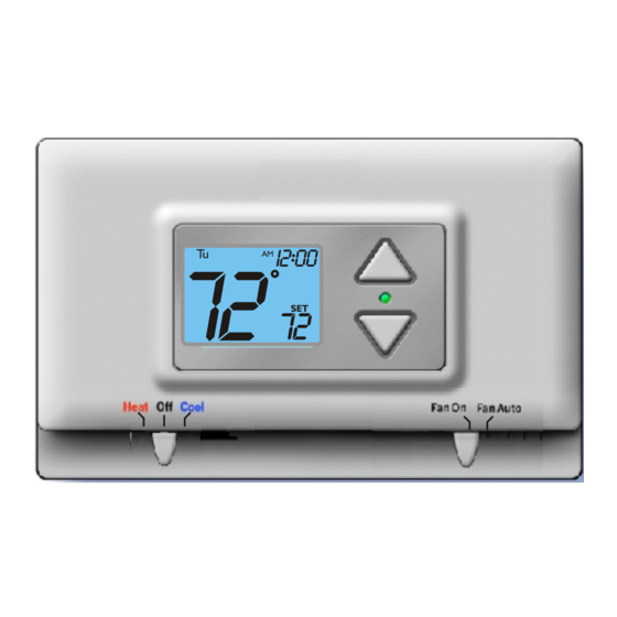
TSTATCCPQ501
Digital Thermostat
TSTATBBPQ501
P474-1035
NOTE: Read the entire instruciton manual before starting the installation.
HEAT
72
I2:00
Tu
AM
&
72
SET
COOL
5+2 DAY PROGRAMMABLE
1-STAGE HEAT, 1-STAGE COOL
Form: IM-TSTAT-22
Cancels: New
Printed in U.S.A.
Catalog No. 63TS-TA12
Advertisement
Table of Contents

Summary of Contents for Heat & Cool TSTATCCPQ501
-
Page 1: Installation Instructions
Installation Instructions TSTATCCPQ501 Digital Thermostat TSTATBBPQ501 P474-1035 NOTE: Read the entire instruciton manual before starting the installation. HEAT I2:00 & COOL 5+2 DAY PROGRAMMABLE 1-STAGE HEAT, 1-STAGE COOL Form: IM-TSTAT-22 Cancels: New Printed in U.S.A. Catalog No. 63TS-TA12... -
Page 2: Table Of Contents
Table Of Contents SAFETY WARNINGS PREPARATION REMOVE OLD THERMOSTAT INSTALLATION AND BATTERY REPLACEMENT WIRE CONNECTIONS JUMPER CONFIGURATION TEST OPERATION TROUBLESHOOTING Patents Pending 4/03 Page 1... -
Page 3: Safety Warnings
Safety Warnings Follow Installation Instructions carefully. CAUTION DISCONNECT POWER TO THE HEATER - AIR CONDITIONER BEFORE REMOVING THE OLD THERMOSTAT AND INSTALLING WARNING THE NEW THERMOSTAT. CAUTION The 2 Alkaline “AA” batteries must be replaced at least every 12 months to assure proper operation. The thermostat will display the Low Battery code (fig. -
Page 4: Preparation
Step #1 Preparation Proper installation of the thermostat will be accomplished by following these step Heat Off Cool Fan On FanA uto by step instructions. If you are unsure about any of these steps, call a qualified technician for assistance. These tools will be required: Heat Off Cool Fan On FanA uto... -
Page 5: Remove Old Thermostat
Step #2 Remove & Replace Old Thermostat Remove the cover of the old thermostat. If it does not come off easily check for Heat Off Cool Fan On FanA uto screws. Loosen the screws holding the thermostat base or subbase to the wall, and lift away. Heat Off Cool Fan On FanA uto Disconnect the wires from the old... -
Page 6: Installation And Battery Replacement
Step #3 Installation and Battery Replacement Open The New Thermostat The top of the thermostat housing has two (2) screw- driver slots to assist when separating. SCREWDRIVER SLOTS To pull the housing apart, insert a small blade screw- driver into the slot and rotate 90 . This will release the top housing snaps. - Page 7 Battery Replacement IF THE THERMOSTAT IS NOT SYSTEM POWERED REPLACE WITH ALKALINE BATTERIES AT LEAST ONCE EVERY YEAR, OR WHEN THE “LOW BATTERY” ICON APPEARS (pages 2,5). POSITION BATTERIES AS SHOWN USE “AA” SIZE USE “AA” SIZE ALKALINE BATTERIES ALKALINE BATTERIES Page 6...
-
Page 8: Wire Connections
Step #4 Wire Connections If the terminal designations on your old Heat Off Cool Fan On FanA uto thermostat do not match those on the new thermostat, refer to the chart below, or the wiring diagrams that follow. Install on the Wire from the old thermostat new thermostat... - Page 9 Sample Wiring Diagrams 4 Wire, 1 Stage Cooling, 1 Stage Residential Gas or Electric Heat *, Electric Cool, split systems & package Gas or Electric Heat units Common wire optional 4 Conductor 18 to 22 gauge unshielded cable from the thermostat to the equipment.
- Page 10 Sample Wiring Diagrams 4 Wire, 1 Stage Cooling, 1 Stage Heat-Heat Pump with O reversing valve*. Residential Heat Pumps, split systems & package units, with no auxiliary heat. Common wire optional 4 Conductor 18 to 22 gauge unshielded cable from the thermostat to the equipment.
- Page 11 Sample Wiring Diagrams 4 Wire, 1 Stage Cooling, 1 Stage Heat-Heat Pump with B reversing valve*. Residential Heat Pumps, split systems & package units, with no auxiliary heat. Common wire optional 4 Conductor 18 to 22 gauge unshielded cable from the thermostat to the equipment.
- Page 12 Sample Wiring Diagrams 3 Wire, 1 Stage Heat Residential Gas or Electric Heat units with a separately controlled fan. Common wire optional 3 Conductor 18 to 22 gauge unshielded cable from the thermostat to the equipment. POWER GAS OR ELECTRIC HEAT Common wire is optional in all installations.
- Page 13 Sample Wiring Diagrams 2 Wire, 1 Stage Gas Heat Residential Gas or Millivolt units. Common wire optional 2 Conductor 18 to 22 gauge unshielded cable from the thermostat to the equipment. POWER GAS OR ELECTRIC HEAT Common wire is optional in all installations. If a common wire is not used the thermostat must be powered by the two AA Alkaline batteries (page 6).
- Page 14 Sample Wiring Diagrams 3 Wire, 1 Stage Cooling Residential Electric Cool units Common wire optional 3 Conductor 18 to 22 gauge unshielded cable from the thermostat to the equipment. POWER COOLING Common wire is optional in all installations. If a common wire is not used the thermostat must be powered by the two AA Alkaline batteries (page 6).
-
Page 15: Jumper Configuration
Step #5 Jumper Configuration Figure-A) IF THERMOSTAT IS NOT SYSTEM POWERED REPLACE WITH ALKALINE BATTERIES ONCE EVERY YEAR USE “AA” SIZE USE “AA” SIZE ALKALINE BATTERIES ALKALINE BATTERIES Jumper and Jumper are shown in the factory default positions for typical gas Heat Off Cool Fan On FanA uto furnace heating with electric cooling. - Page 16 Step #5 Jumper Configuration Figure-B) IF THERMOSTAT IS NOT SYSTEM POWERED REPLACE WITH ALKALINE BATTERIES ONCE EVERY YEAR USE “AA” SIZE USE “AA” SIZE ALKALINE BATTERIES ALKALINE BATTERIES Jumper is used to select Fan On (G) with Heat (W). Jumper shown in the Heat Off Cool Fan On FanA uto...
-
Page 17: Heat Pump Applications
Step #5 Jumper Configuration Figure-C) IF THERMOSTAT IS NOT SYSTEM POWERED REPLACE WITH ALKALINE BATTERIES ONCE EVERY YEAR USE “AA” SIZE USE “AA” SIZE ALKALINE BATTERIES ALKALINE BATTERIES Jumper and Jumper are used to select heat pump operation. Note: Thermostat Heat Off Cool Fan On FanA uto Does Not Have Auxiliary Heat / Emergency... -
Page 18: Test Operation
Step #6 Test Operation Turn on the power to the Heating/Air Conditioning system. Heat Off Cool Fan On FanA uto Adjust the Slide Switch until it is located under the word HEAT on the thermostat. Heat Off Cool Fan On FanA uto Press the Up or Down buttons until the set temperature is 10 degrees above room temperature. -
Page 19: Troubleshooting
Troubleshooting SYMPTOM: The slide switches on the thermostat are very difficult to move. Heat Off Cool Fan On FanA uto CAUSE: The backplate of the thermostat is deformed by being screwed tightly into a wall that is not perfectly flat. REMEDY: Loosen the screws holding the thermostat into the wall. - Page 20 Troubleshooting SYMPTOM: The air conditioning does not attempt to turn on. Heat Off Cool Fan On FanA uto CAUSE: The cooling setpoint is set too high or the Mode Switch is not set for Cool, or the batteries are too weak. REMEDY: Consult the Normal Operation section of this manual to lower the cooling setpoint and to correct the...
- Page 21 Finally, if the Evening Start Time is set for 5:30pm, then the Night Start Time MUST be programmed for any time AFTER the 5:30pm Night Start Time. Battery Stat TSTATBBPQ501 TSTATCCPQ501 P474-1035 Tested to Comply with FCC Standards FOR HOME OR OFFICE USE 4Z95 Form No.
Need help?
Do you have a question about the TSTATCCPQ501 and is the answer not in the manual?
Questions and answers