Subscribe to Our Youtube Channel
Summary of Contents for Smart Tracker GT06
-
Page 1: User Manual
GPS Vehicle tracker (GPS+GSM+SMS/GPRS) User Manual (Version 2.2) Please read this manual carefully before attempting installation and online activation. Pictures are for indication and illustration purposes only. -
Page 2: Accessories
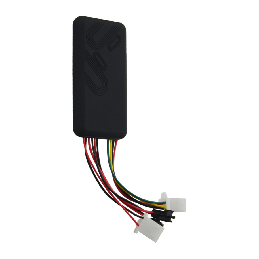
1. Accessories: Please check the accessories before using. Pictures are for indication and illustration purposes only. 2. Features: ● GSM 850/900/1800/1900 Quad band ● Wide voltage (input range): 9-36V DC ● GPS continuous positioning, GPRS timing interval ● Check location via SMS ●... -
Page 3: Interface Introduction
2.1 Red LED (power/working status) LED Status Meaning Flashing (interval 0.1s) Low battery indication Continuously in bright state Charging Slow flashing(interval 0.2s) Full charge Continuously in dark state Low battery / power off Slow flashing(flash 0.1s after every 2s) Working normally Green LED(GSM status indicator) LED Status Meaning... -
Page 5: Method Of Installation
4. Method of installation 4.1. Preparation before installation 4.1.1 Open the packing box to check whether the type of device is correct and whether the accessories are included, or else please contact your distributor. 4.1.2 Choose SIM card: each device needs to insert a GSM SIM card. Please refer to the distributor’s suggestions to choose the SIM card. - Page 6 -shelter in the decorated board below the front windshield; -shelter around the front instrument panel (non-metallic material face); -in the decorated board below back windshield; Notice: if the windshield is pasted with metal thermal-protective coating or heating coating, It may affect the receiving signal. In this case, please change the installation place.
-
Page 7: Device Wiring Diagram
Notes of the relay wiring The relay wiring of pump: oil connectors of both ends are a fine white line (85) and a fine yellow line (86). The fine white line (85) is connected to vehicle positive power (+12V). The fine yellow line (86) is connected to the device relay control line. -
Page 8: Parameter Setting
5. Cautions of device wiring 5.1 Power/ACC/Tele-cutoff (petrol/electricity) control line (4 pin) 5.1.1 The standard voltage is 9V-36V DC. Please use the power line which provided by the manufacturer. The red line is the positive. The black line is the negative. -
Page 9: Dns Setting
Please send the SMS command below: APN,APN’s Name# APN command format: APN,internet#(“internet” is the APN of carrier) the device will reply ”OK” if e.g: setting successfully. Note:The APN of some countries have user name and password, you may need to send SMS command as following: APN,APN’s Name,user name,password# APN command format: e.g:APN,internet,CLIENTE,AMENA#... - Page 10 For example: SOS,A,13510905991# means to set the first number as SOS number(After “A”, there is one comma) SOS,A,,13510905992# means to set the second number as SOS number(After “A”, there are two commas) SOS,A,,,13510905993# means to set the third number as SOS number(After “A”, there are three commas) If set successfully, there is a “success”...
-
Page 11: Delete Center Number
6.7 Delete the center number Send a SMS command to the device to delete the center number. The command is: CENTER,D# For example: CENTER,D# If set successfully, there is an “OK” reply SMS. Note: Only the SOS number can be used to delete center number successfully. 6.8 Check parameter settings Send a SMS command to the device to check the device’s setting. -
Page 12: Sensor Alarm Time Setting
upload positioning data to the platform server every 10s. Users can modify GPRS time sending interval “TIMER,time(second)#”. The time ranges from 10-18000s For example: TIMER,10# It means the device will upload data to the server every 10s. 6.11 Sensor alarm time setting When the vehicle power is off and ACC is in low-level, if ACC is off over 10 minutes, the device will enter sensor alarm state. -
Page 13: Check Location
SIM card and power on. During the working time, it can upload data to server every 10 seconds. 7.2 Check location 7.2.1 Via SMS 7.2.1.1 Send SMS command “POSITION” to the SIM number of GT06. If the device succeed to get the address, it will reply a location Google Map link. <Date Time:10-11-23 23:42:51>... - Page 14 numbers in circles. If nobody answers, the call just keeps 3 loops at most. At the meantime, the device will upload SOS alarm data to the server. And it will send: Cut Power!<Date Time:11-06-17 14:53:06>,http://maps.google.com/maps?q=N22576713,E113.916585 Note: The specific numbers should be preset, just refer to 6.4 7.5 Low battery alarm When the device is only working with battery, once the internal voltage of battery is less than 3.7V, device will send low battery alarm sms to specific...
-
Page 15: Web Based Tracking Online Activation
Send oil cut-off command on platform. To make sure the security of vehicle, tracker can only indicate to cut off oil when GPS is in valid position status, and the speed is less than 20KM/H or in static. It needs password and platform account password is needed when sending oil cut off command. - Page 16 of the SIM card’s slot. 4) Whether ACC ignition cable is connected, please turn on the ACC with key after it is connected. 5) Check the LEDs’ status. In normal working status, the red LED is in solid bright or flashing; green LED and blue LED are both in solid bright. 6) Check whether GPS is located, if not, please drive to the open areas for positioning.
- Page 17 Warranty card of GPS Vehicle tracker Special statement: 1. Specifications of this product subject to change without further notice. 2. Any change about the appearance and color is subject to the real object. 3. Warranty card applies to the product with the IMEI number listed below. 4.
-
Page 18: Maintenance Records
Maintenance records Record one Maintenance unit Date Fault description Maintenance status IMEI number Serviceman Record two Maintenance unit Date Fault description Maintenance status IMEI number IMEI number...

Need help?
Do you have a question about the GT06 and is the answer not in the manual?
Questions and answers