Table of Contents
Advertisement
Advertisement
Table of Contents

Related Manuals for HYOSUNG Comet 650S


Summary of Contents for HYOSUNG Comet 650S
- Page 1 HYOSUNG MOTORS & MACHINERY INC. SERVICE MANUAL 99000-94910...
- Page 2 HYOSUNG vehicles. Without such knowledge and skills, you should not attempt servicing by relying on this manual only. Instead, please contact your nearby authorized HYOSUNG motorcycle dealer. HYOSUNG MOTORS & MACHINERY INC. COPYRIGHT HYOSUNG MOTORS & MACHINERY INC. 2005.
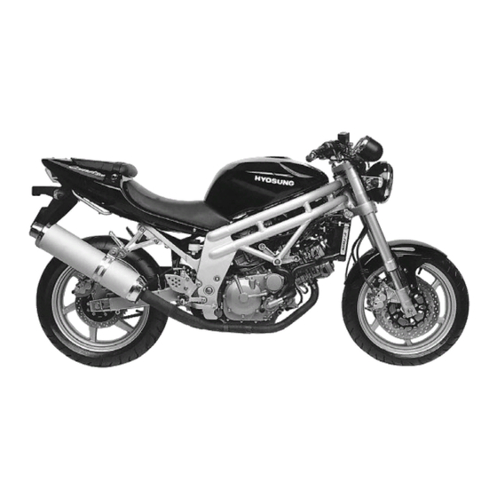
- Page 3 (Standard type)
- Page 4 (Sports type) NOTE Difference between photographs and actual motorcycles depends on the markets.
-
Page 5: How To Use This Manual
HOW TO USE THIS MANUAL TO LOCATE WHAT YOU ARE LOOKING FOR: 1. The text of this manual is divided into sections. 2. As the title of these sections are listed on the previous page as GROUP INDEX, select the section where you are look- ing for. -
Page 6: General Information
GENERAL INFORMATION CONTENTS EXTERIOR ILLUSTRATION 6 (1-7-1) SPECIFICATIONS 9 (1-8) -
Page 7: General Information
1-7-1 GENERAL INFORMATION EXTERIOR ILLUSTRATION [ (Standard type)] Turn signal lamp (Rear) Tail / Brake lamp Rear License plate lamp reflector Turn signal lamp (Front) Head lamp Passenger footrests (WHEEL BASE) (LENGTH) -
Page 8: Exterior Illustration
GENERAL INFORMATION 1-7-2 EXTERIOR ILLUSTRATION [ (Sports type)] Turn signal lamp (Rear) Tail / Brake lamp Rear reflector License plate lamp Turn signal lamp (Front) Head lamp Passenger footrests (WHEEL BASE) 1,435 (LENGTH) 2,060... - Page 9 1-7-3 GENERAL INFORMATION EXTERIOR ILLUSTRATION [ Turn signal lamp (Rear) Tail / Brake lamp Rear License plate lamp reflector Turn signal lamp (Front) Head lamp Passenger footrests (WHEEL BASE) (LENGTH)
-
Page 10: Specifications
GENERAL INFORMATION 1-8 SPECIFICATIONS DIMENSIONS AND DRY MASS I T E M (Standard type) (Sport type) Overall length 2,060 mm (81.1 in) 740 mm (29.1 in) Overall width 655 mm (25.8 in) Overall height 1,125 mm (44.3 in) 1,435 mm (56.5 in) Wheelbase 150 mm (5.9 in) Ground clearance... - Page 11 1-9 GENERAL INFORMATION CHASSIS I T E M (Standard type) (Sport type) Front suspension Telescopic type Rear suspension Swingarm type Steering angle 27 (right & left) Caster 25.5 Trail 74 mm (2.91 in) Front brake Double disk brake Rear brake Disk brake Front tire size 120/60 - ZR 17 55W...
-
Page 12: Periodic Maintenance
PERIODIC MAINTENANCE CONTENTS MAINTENANCE PROCEDURES CARBURETOR 12 (2-7) CLUTCH 13 (2-9-1) ENGINE COOLANT 16 (2-20) -
Page 13: Periodic Maintenance
2-7 PERIODIC MAINTENANCE MAINTENANCE PROCEDURES CARBURETOR Inspect Interval Inspect Initial 1,000 km and Every 6,000 km. ¢`IDLE SPEED NOTE Make this inspection when the engine is hot. Connect an engine tachometer to the high tension cord. Start up the engine and set its speed at anywhere 1,300 and 1,500 rpm by turning throttle stop screw Engine idle speed 1,300 1,500 rpm... - Page 14 PERIODIC MAINTENANCE 2-9-1 CLUTCH Inspect Interval Inspect Initial 1,000 km and Every 6,000 km. Clutch play should be 2 mm(0.08 in) as measured at the clutch lever holder before the clutch begins to disengage. If the play in the clutch is incorrect, adjust it in the following way : A basis adjustment can be done by the clutch lever adjuster...
- Page 15 2-9-2 PERIODIC MAINTENANCE ¢`FOOTREST POSITION ADJUSTMENT & have 3 type of the footrest position, right and left. To change the position, remove the 8mm wrench bolts and install the bolts to the desired position by using the hexagon wrench 6mm. &...
- Page 16 PERIODIC MAINTENANCE 2-9-3 ¢`GEARSHIFT LINK ROD (FOR ¡” ¡» & ¡” ¡» S OPTIONAL PARTS) When the footrests in position , exchange the gearshift ¤Ø link rod for appropriate riding position. Position : Install the gearshift link rod Position ¤Œ : Install the gearshift link rod NOTE The gearshift link rod ¤Œ...
-
Page 18: Electrical System
ELECTRICAL SYSTEM CONTENTS IGNITION SYSTEM 18 (6-6) LAMP 19 (6-16-1) -
Page 19: Ignition System
6-6 ELECTRICAL SYSTEM IGNITION SYSTEM IGNITER Using the pocket tester(R 1 range), measure the resistance between the terminal in the following table. CAUTION Numerical value may differ a little according to the tester. Please remind that there may be a defect which can not be identified even though the measurement by using the tester indicates a low voltage. - Page 20 ELECTRICAL SYSTEM 6-16-1 LAMP ¢` HEAD LAMP REPLACEMENT OF HEAD LAMP BULB Remove the under cowling. ( (Refer to page 7-1-2 ~ 3) Remove the body cowling. (Refer to page 7-1-4 ~ 5) Remove the head lamp coupler Remove the dust cover...
- Page 21 6-16-2 ELECTRICAL SYSTEM Remove the socket spring Remove the bulb and replace the new bulb. Remove the head lamp "H I" bulb with the same manner of the head lamp "LOW" bulb removal. Reinstall the head lamp bulb in the reverse order of head lamp bulb removal.
- Page 22 ELECTRICAL SYSTEM 6-17-1 COMBINATION METER Remove the combination meter. Disassemble the combination meter as shown in the illustration. INSPECTION Using the pocket tester, check the continuity between lead wires in the following illustration. If the continuity measured incorrect, replace the respective part.
- Page 23 6-17-2 ELECTRICAL SYSTEM 12V, 1.7W, T6.5 HEAD LAMP DISPLAY(VFD) LOW TURN R HIGH TURN L ILLUM ILLUM TACHO METER B BW Lg BW SIGNAL...
-
Page 24: Chassis
CHASSIS CONTENTS EXTERIOR PARTS 24 (7-1-1) HANDLEBARS 29 (7-13-1) STEERING 33 (7-23) -
Page 25: Exterior Parts
7-1-1 CHASSIS EXTERIOR PARTS ¢`REAR CARRIER REMOVAL Open the rear seat with the ignition key. Remove the rear carrier mounting bolts separate the rear carrier INSTALLATION Reassemble the rear carrier in the reverse order of removal. To reinstall the rear seat, slide the seat hook into the seat hook retainer and push down firmly until the seat snaps into the locked position. - Page 26 CHASSIS 7-1-2 ¢`UNDER COWLING (Only ¡” ¡» ) ) Under cowling RH Under center cowling Under cowling LH Under center cowling grill...
- Page 27 7-1-3 CHASSIS REMOVAL Remove the under cowling screws at the rightside. Remove the under cowling screws at the leftside.
-
Page 28: Body Cowling
CHASSIS 7-1-4 BODY COWLING ¤ Windscreen ¤ºBody side cowling inner RH ¤ Air duct cowling LH ¤ŁMeter panel ¤ Body side cowling lower RH ¤ Body center lower cowling ¤ØBody side cowling RH ¤ Body side cowling lower LH ¤ŒBody side cowling LH ¤... - Page 29 7-1-5 CHASSIS § REMOVAL Remove the body cowling screw at the rightside. Remove the body cowling screw at the leftside. Remove the two cowling brace bolts. Remove the speedometer lead wire and head lamp lead wire. § REMOUNTING Tighten the two cowling brace bolts. Cowling brace bolt : 22 ~ 35 N¡⁄m (2.2 ~ 3.5 kg¡⁄m)
- Page 30 CHASSIS 7-13-1 HANDLEBARS (Standad type) ¢` Refer to the service manual (99000-94810) page 7-13 ~ 14 (Sports type) & ¢` Handlebar composition RH Rear view mirror assembly RH Handlebar switch assembly RH Handlebar composition LH Rear view mirror assembly LH Handlebar switch assembly LH ¡Æ...
- Page 31 7-13-2 CHASSIS ¡Æ HANDLEBAR LEFT SIDE PARTS REMOVAL Remove the left handlebar switches. Remove the handlebar balancer and grip Remove the clutch lever holder. Loosen the handlebar clamp bolts, right and left. Loosen the front fork upper clamp bolt, right and left. Remove the steering stem upper bracket by removing the steering stem head nut.
- Page 32 CHASSIS 7-14-1 Remove the handlebar holder bolt, right and left. Draw out the handlebars to upward. ¡Æ REMOUNTING Remount the handlebar in the reverse order of removal. Pay attention to the following point : Install the handlebars temporary. Install the steering stem upper bracket. Tighten the steering stem head nut.
- Page 33 7-14-2 CHASSIS When remounting the clutch lever holder, align the holder s mating surface with punch mark on the Upper handlebar. Clutch lever holder Handlebar When remounting the front brake master cylinder onto Upper the handlebar, align the master cylinder holder s mating surface with punch mark on the...
-
Page 34: Removal And Disassembly
CHASSIS 7-23 STEERING (Standad type) ¢` Refer to the service manual (99000-94810) page 7- 23 ~ 25 (Sports type) & ¢` ¢`REMOVAL AND DISASSEMBLY Remove the under cowling and body cowling. ( (Refer to page 7-1-2 ~ 5) Remove the body cowling. ( (Refer to page 7-1-4 ~ 5) Take off the front wheel. - Page 35 7-24 CHASSIS Remove the handlebar clamp bolts. Remove the steering stem head nut and take off the steering stem upper bracket Remove the steering stem nut and draw out the steering stem. Clamp wrench : 09940-10122 Take off the steering stem lower bracket CAUTION Hold the steering stem lower bracket by hand to prevent from falling.
- Page 36 CHASSIS 7-25-1 ¢`INSPECTION Inspect and check the removed parts for the following abnormalities. ¡⁄ Handlebar distortion. ¡⁄ Handlebar clamp wear. ¡⁄ Abnormality operation of bearing. ¡⁄ Worn or damaged races. ¡⁄ Distortion of steering stem. ¢`REASSEMBLY Reassemble and remount the steering stem in the reverse order of disassembly and removal, and also carry out the following steps : Apply SUPER GREASE ¡...
- Page 37 7-25-2 CHASSIS Tighten the handlebar clamp bolts, right and left. Handlebar clamp bolts : 22 ~ 35 N¡⁄m (2.2 ~ 3.5 kg¡⁄m)
-
Page 38: Servicing Information
SERVICING INFORMATION CONTENTS SERVICE DATA 38 (8-20) WIRE AND CABLE ROUTING 39 (8-24-1) WIRING DIAGRAM 47 (8-28) -
Page 39: Service Data
8-20 SERVICING INFORMATION SERVICE DATA WATTAGE Unit : W ITEM SPECIFICATION H1 : 55W Head lamp H3 : 55W License plate lamp Brake/Tail lamp 21/5W Turn signal lamp Front : 10W 2 / Rear : 10W 2 llumination lamp 1.7W 2 Neutral indicator lamp Turn signal indicator lamp (Right &... - Page 40 09408-00002 CLIP, T/CABLE & R/CABLE 36618-30610 TUBE, SPEEDOMETER LEAD WIRE 09407-254A1 09407-20406 09407-20406 09407-20406 SPEED SENSOR 59470HN910 59460HN910 HOSE COMP, FRONT BRAKE R HOSE COMP, FRONT BRAKE L 51511HN910 JOINT, FT BRAKE HOSE...
- Page 41 8-24-2 SERVICING INFORMATION...
- Page 42 CARBURETOR ASS’Y 58410HP920 CABLE COMP, STARTER VIEW A...
- Page 43 8-25-2 SERVICING INFORMATION...
- Page 44 61610HM810 GUIDE, RR BRAKE HOSE NO.2 69480HM810 61510HM810 HOSE COMP, REAR BRAKE GUIDE, RR BRAKE HOSE NO.1 Apply THREAD LOCK "1324" CYLINDER ASS’Y, R/R MASTER when install GUIDE NO.2...
- Page 45 TH/CABLE, RE/CABLE, C/CABLE, ST/CABLE are routing into the bracket hole. Each cable is no twisted. CARBURETOR BRACKET 09407-14403 ENGINE EARTH MOTOR LEAD WIRE Rr.STOP S/W THERMOSTAT 09407-20406 LEAD WIRE, STARTER MOTOR PIPE COMP, 2ND AIR FRONT 58200HN910 CABLE ASS’Y, CLUTCH...
- Page 46 SERVICING INFORMATION 8-27-1 09404-06401 WIRING HARNESS TO WATER TEMP GAUGE FRONT CYLINDER REAR CYLINDER CAUTION FOR HIGHTENTION CORD INSTALLATION DIRECTION...
- Page 47 8-27-2 SERVICING INFORMATION 09404-06429 MAGNETO GEAR SHIFT S/W PROP STAND S/W SPROCKET COVER...
- Page 48 WATER TEMP GAUGE HANDLE SWITCH Rh DISPLAY E/G STOP START FRONT BRAKE HAZARD STOP LAMP S/W STOP FREE FREE TACHO PUSH WB O THERMO S/W DIODE #2 HEAD LAMP RELAY FAN MOTOR RELAY IGNITOR IGNITION S/W FAN MOTOR O BW BR TURN RELAY SIDE STAND RELAY CLUTCH LEVER S/W...
- Page 49 Prepared by HYOSUNG MOTORS & MACHINERY INC. 1st Ed. APR. 2005. Manual No. 99000-94910 Printed in Korea...
Need help?
Do you have a question about the Comet 650S and is the answer not in the manual?
Questions and answers