
Summary of Contents for VGuard N series
- Page 1 VGuard N Series 16/8/4 Channels Embedded Net DVR User’s Manual Please read this user’s manual carefully before you use this system. Please keep a user’s manual handy when needed.
- Page 2 Declaration All the specification mentioned in this user’s manual is based on the products when this user’s manual is published. Manufacturer owns the right to alter or change this product with or without notification. All the products specification will base on the product itself.
-
Page 3: Table Of Contents
Chapter 1 : System Specification........6 System Hardware Specification: ..........6 System Function Specification: ............7 Package Content: .................8 Chapter 2 : System Introduction: ........9 System Front Panel: ..............9 USB…………………………………………………………………………….9 Number 1-8 Buttons................9 Number 9 Button...................10 Number 0 Button...................10 ... - Page 4 System Back Panel: ..............13 Power Supply ..................13 Ethernet RJ45-jack................13 USB……………………………………………………………………………13 Power…………………………………………………………………………13 VGA Output...................13 Video Input BNC-jacks ................13 TV Monitor Output BNC-jack..............14 Audio Input RCA-jack................14 Audio Output Earphone-jack ..............14 Input Terminals (Optional) ..............14 ...
- Page 5 Chapter 10 : Network Function ........41 10.1 Network Setup: ................42 10.2 Network Connection Setup:............43 10.3 Remote File Search:..............48 10.4 Remote VGuard N series using IE browser .......49 Chapter 11 : VG Player............58 11.1 Playback Control Panel: .............59 11.2 Search ..................61 11.3 Color Configuration..............61 11.4...
-
Page 6: Chapter 1 : System Specification
VG to AVI Conversion: ...............63 Chapter 1 : System Specification VGuard N series is a new generation embedded DVR system. This system is using the most advanced H.264 compression technique. This technique not only holds the best recording quality and high compression rate. Under the same hard disk sizes, it can save longer video images and audio sounds. -
Page 7: System Function Specification
8. Hard Disk: Support 2 IDE Hard disk 9. Backup Function: Supports 2 USB, to connect to USB disks. 10. Ethernet: RJ45 (100/10Mbps Ethernet) 11. Power: AC115V/60Hz/4A, 230V/50Hz/2A (Typical) 12. Weight: 4.5Kg / 5.5Kg (Net /Gross Weight) 13. Size: 20.5cm x 34cm x 19cm (Length x Width x Depth) 1.2 System Function Specification: 1. -
Page 8: Package Content
PC for Remote monitoring or recording. 24. Firmware Update: Firmware update available from our website at www.vguard.net update/ add / alter the software through USB devices. 1.3 Package Content: Please be cautious when opening up the package to avoid damage to the system. -
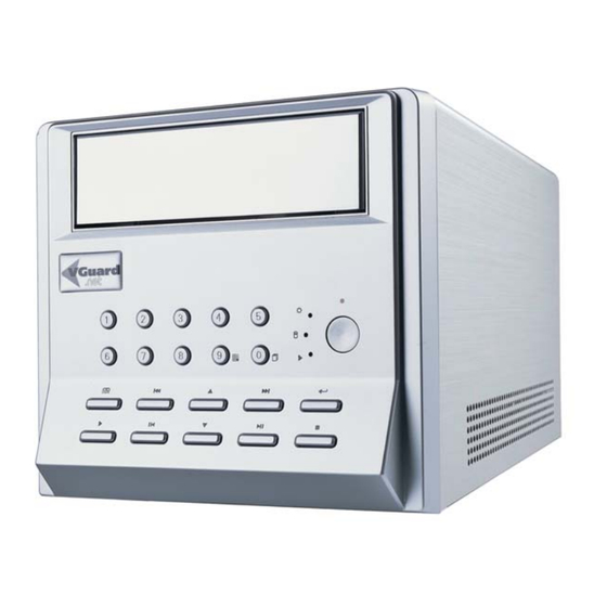
Page 9: Chapter 2 : System Introduction
jacks audio connection cables. (Extra audio connection cables are optional). VGN8C-SRT4: 2* BNC jacks video connection cables. 1* RCA jacks audio connection cables. (Extra audio connection cables are optional). VGN16C-HRT4: 3* BNC jacks video connection cables. 1* RCA jacks audio connection cables. VGN8C-RT4: 1* RCA jacks audio connection cables. -
Page 10: Number 9 Button
camera displayed will be according to the number of button pressed. Under 16 channels model, to select the enlarge images for camera 9-16, you will require to use the split window button (number 9), and switch to the split window images for camera 9-16, When under setting mode, the number button is for setting of number 1-8. -
Page 11: Leftward Button / Playback Backward
sub-window location, Save PIP sub-window location. Leftward Button / Playback Backward 1. Under normal operation: Move selection leftward, Go to last page. 2. Under playback operation: For playback backward. Each backward 160 frames 3. When adjusting PIP sub-window: Move the PIP sub-window to the left. Upward button / Step Playback / Pause Playback 1. -
Page 12: Subtract 1 / Next / Slow Speed Playback
Subtract 1 / Next / Slow Speed Playback 1. Under normal operation: Subtract 1 when setting numbers or next one selection button. 2. Under playback mode: Playback speed will be changes each time you press the button to 1/2 1/8 slow speed playback Downward Button / PIP Function 1. -
Page 13: System Back Panel
2.2 System Back Panel: System’s back panel is mainly for signal connection. Detail information as followed: Power Supply Mark 1: This is for the power supply input socket. You can directly connect to AC 110V/60Hz or 220V/50Hz. Ethernet RJ45-jack Mark 2: This is for RJ45 Internet connection socket. This is for 10Mbps/100Mbps Ethernet Mark 3: This system has 2 USB sockets. -
Page 14: Tv Monitor Output Bnc-Jack
VGuard N system has an IDE interface. It can connect 2 IDE hard disk The setting for the first hard disk is Master and the second as Slave. -
Page 15: Chapter 3 : System Setting
disk is over 250GB, system will automatically separate it into 2 or more same partition sizes. Chapter 3 : System Setting This is used to setup the system for operation needs. This system includes functions like, motion detection, alarm functions, security functions, Internet functions and I/O control etc. -
Page 16: Time/Display Setup
3.2 Time / Display Setup TIME/DISPLAY SETUP 1.DATE 2006/5/8 2.TIME 18:00:08 3.TIME ZONE GMT+08 4.SYSTEM TIME 5.CAMERA NAME 6.SYSTEM STATUS 7.MAIN+SUB DISPLAY Time / Display setup is for setting the system time and display status. User the up and down button to select and press the select button to confirm setting: Date: Use the leftward and rightward button to select year, month and date. -
Page 17: Camera Setup
changing to “On”, or when enlarge one of the camera, this camera will not be enlarge as full screen, instead it will be shown as main screen and other camera images will be shown around the main screen in smaller screen. 3.3 Camera Setup CAMERA SETUP : CAMERA1 1.CAMERA NAME... -
Page 18: Alarm Setup
channel per hour. Display: Defaulted is on (activate), you can change to off if display not require. Brightness: Brightness adjustment. Defaulted is 115, adjusting range from 0-255, 0 is the darkest and 255 is the brightness. Contrast: Contrast adjustment. Defaulted is 130, setting range from 0-225, 0 is the lowest and 255 is the highest. - Page 19 ALARM SETUP : CAMERA1 1.VIDEO LOST CHECK 2.MOTION DETECT 3.ALARM SOUND 4.ALARM INTERVAL 5.MASK1 00 00:00 00 6.MASK2 00 00:00 00 7.MASK3 00 00:00 00 8.MASK4 00 00:00 00 9.OUTPUT TRIGGER -- -- -- -- Video Lost Check: Checking video lost. Defaulted is on (activate) so when video lost, system will trigger alarm.
-
Page 20: System Setup
relay output control terminals for selection. This output control terminals is optional. 3.5 System Setup SYSTEM SETUP 1.VIDEO MODE NTSC 2.RECORD SPEED 3.VIDEO QUALITY 4.SCAN TYPE QUAD DISPLAY 5.SCAN INTERVAL 6.AUTO RECORD 7.LIVE AUDIO 8.ALARM RECORD 9.VGA-PIP Video Mode: Video modes include the selection of NTSC and PAL. Users must change it according to your local video mode. -
Page 21: Network Setup
Live Audio: When this is activated, and you had connected audio input to the correspondence cameras, you are able to have live audio monitoring when the sound is connect to a speaker. ALARM RECORD: When system not under recording mode, after activated of this function, the system will start recording after alarm triggered. -
Page 22: Connection
1.LISTEN PORT 50000 50000 2.MODE 3.GET IP AUTO GET IP Listen Port: Listen Ports for the N Series, LAN users use the first value; WAN users use the second value. Defaulted value is 50000. Internet connection will require changing the... -
Page 23: Wan Mode
communication ports. Please refer to Chapter 10 Network Connection Setup. Mode: There are three connection modes. LAN mode, WAN mode and Dail-Up mode using (PPPoE). Get IP: Under LAN mode, IP setup can be Auto get IP and manually set IP. If the LAN network is with DHCP function, the IP address can be automatically got. -
Page 24: Dial-Up Mode
NETWORK SETUP : CONNECTION 1.LISTEN PORT 50000 50000 2.MODE DIAL-UP 3.USERNAME MANUAL SETUP IP 4.PASSWORD 000.000.000.000 5.AUTO CONNECT DIAL-UP Mode Users with PPPoE connection can select Dial-Up Mode. User Name, Password: Username and password is require to enter when connection. There might not be a small letter available for some systems, User will require putting “+”... -
Page 25: Ddns Setup
Primary IP, Secondary IP: User can setup 2 sets of DNS IP. DDNS Setup VGN4/8C-RT4 system don’t support DDNS function, this setup page would not be shown. Users can uses left right button to enter the DDNS Dynamic Domain Name Server setup. If the IP for VGN Embedded DVR is a real IP in Internet, no matter is a fixed IP or Floating IP, you can apply a Dynamic Domain Name for this VGN Embedded DVR. -
Page 26: User
DOMAIN NAME Please enter the domain name you applied from DDNS supplier. USER NAME Please enter the user name you register with DDNS supplier. PASSWORD Enter the password you register with DDNS supplier. DDNS SERVER Select the DDNS supplier you select. User User can use left or... -
Page 27: Network Info
allowed to monitor. Unauthorized camera will not be displayed. From left to right are camera 1/ camera 2/ camera 3/ camera4. Camera 5-8: This is to display the camera that the remote user is allowed to monitor. From left to right are camera 5/ camera 6/ camera 7/ camera8. -
Page 28: Output
Input/Output setup is to setup the output status and the input’s signal status. Users must setup the output status to correctly control the external devices. Input is to detect the status of the device. When input is triggered, then the system can corresponded according to the setting. When enter this setup menu, it will be the setup of output. -
Page 29: Program
condition) and NC (Short under normal condition). Wrong setting will cause error action. When input potential is “---“, it means disable. Input potential is “High” will require to use NO (Open under normal condition) and when input potential is “Low”, the NC (Short under normal condition) will be used. -
Page 30: Advanced Setup
3.9 Advanced Setup ADVANCED SETUP 1.STOP RECORD 2.LOGOUT 3.LOGOUT AND RECORD 4.PASSWORD ---------- 5.UPDATE FIRMWARE 6.LOAD DEFAULT 7.FORMAT DVD(OPT) 8.SCAN HDD 9.FORMAT HDD HDA1 147.4G Stop Record: This system’s recording status is not able to stop recording from any button on the front panel. This is for security reason. -
Page 31: Chapter 4 : Record
would avoid the error setting by the users, which might cause abnormal operating of the system. FORMAT DVD(OPT) This is an optional model. This support the burner (DVD burner) by USB interfaces. User can use DVD±R and DVD±RW to backup Video files. It is suggest to format DVD±RW disks on this VGN Embedded DVR to make sure this function can work normally. -
Page 32: Activate Record Manually
as camera 1-8, a total of 8 image section (VGN8C-RT4). Status Section: Bottom right hand side is the status section, it display the system time and hard disk status. The above left hand side picture is displayed when hard disk is not installed. When hard disk is installed then it will display the partition, free spaces and total capacity messages as above right hand side pictures. -
Page 33: Auto Record
will be able to see the symbol or whether the recording indicator from the front panel. Auto Record If the Auto record is set as ON under system setting, system will automatically start recording when turned on. Stop Record This system will not be able to stop recording from any button on the front panel. -
Page 34: Assign Time For Playback
Time display: On playback images, recording time and date will be display on the right bottom side of the images for every camera. Pause: When is displayed, it means that the playback image is under paused. 5.1 Assign Time for Playback Press playback button, then the following menu will be shown: PLAYBACK... -
Page 35: Playback Operation Buttons
13 00 07 14 00 09 5-8 565.0M 13 00 07 14 00 09 1-4 718.0M 12 00 05 13 00 07 5-8 636.1M 12 00 05 13 00 07 1-4 590.2M 11 00 06 12 00 05 5-8 379.9M 11 00 06 12 00 05 1-4 412.9M 10 00 03 11 00 06 5-8... -
Page 36: Chapter 6 : Pip Function
Chapter 6 : PIP Function PIP functions only support VGA monitor output. This system does not support TV monitor output for PIP function. If user only connects to TV monitoring output, please do not activate this VGA-PIP function. When system is recording and playing back files at the same time, users can use the record and playback button to switch between record or playback images. -
Page 37: Chapter 7 : Alarm Log
If cancel button is pressed after adjustment, then the new location will not be saved. If select/confirm button is press after adjustment, then the new location will be saved. When user activates PIP function next time, PIP will display at the new location saved. Chapter 7 : Alarm Log This system is with alarm function. -
Page 38: Chapter 8 : I/O
detail alarm log: ALARM LOG 2006-05-05 13 02 25 CAMERA5 LOSS END 13 00 25 CAMERA5 LOSS START 12 32 35 CAMERA3 MOVE END 12 30 35 CAMERA3 MOVE START 11 02 32 INPUT1 11 02 02 INPUT1 START 10 35 24 CAMERA2 LOSS END If under the alarm log is recorded because of motion, use the up and down buttons to select to the record and use select/confirm button to select to playback the images. -
Page 39: Output Control Setup
low potential, then the system will triggered the alarm. When input potential is set at low, it means it is low potential under normal condition, you will require to use NC (Close) device. When sensor triggered, it will become open circuit, and then the input terminal will detect high potential, then the system will triggered the alarm. -
Page 40: Chapter 9 : File Backup
Use this output control to shut off the alarm sound when alarm triggered. Use up, down buttons to select the outputs and press select button to adjust output from OFF-ON or ON-OFF. Chapter 9 : File Backup By connecting USB devices (USB flash disk , USB Hard disk and USB DVD Burner) to the system, you will able to backup file. -
Page 41: Chapter 10 : Network Function
FILE LIST 2006-05-03 START CAMERA LENGTH 14:00:00 15:00:00 660.0M 14:00:00 15:00:00 662.3M 13:00:00 14:00:00 680.4M 13:00:00 14:00:00 560.0M 12:00:00 13:00:00 702.3M 12:00:00 13:00:00 720.4M Use up and down button to select the file time and camera number for backup, and press the select button the following will be shown: FILE BACKUP 2006-05-03 1. -
Page 42: Network Setup
monitoring/recording, it can also connect to other DVR embedded Standalone System , it can also monitoring other PC based images to form a full network. (Require using the same version remote software V5.0 or above). You will require selecting a computer as server, using the CD ROM we provided to install the software. -
Page 43: Network Connection Setup
192.168.1.11:40000 < -------- > 211.172.12.34:40000 This means, the Server IP setting for VGN embedded DVR network setup or Chateau system address setup: If under Internet to connect to server, all Server IP address is 211.172.12.34.If under the same LAN with the server, then the Server IP address is 192.168.1.11. - Page 44 VGN Embedded DVR network setup 1. If the recording site (VGN Embedded DVR, and Chateau) is using real IP address for internet (ie.211.175.21.43) VGN Embedded DVR network setting is as follow: Communication Port Setup: LAN: 50000; WAN no special value required.
- Page 45 User must setup the network connection for the computer system which installed with Chateau program to monitor or monitored (Installed with VGuard Card) by other system. Enter System Setup for Chateau program. Select Address book setting: Select New to add a new server IP address: Key in a Server name for this system.
- Page 46 There are four types for remote: Server; IP, PC DVR and Embedded DVR. In these, Server supports connection from several remote points from PC DVR and Embedded DVR. PC DVR and Embedded DVR can only support point to point connection. IP then used as remote alarm between PC DVR.
- Page 47 correspondence to this system will display: Press button, if password correct, the following “Remote Channel Select” will be shown as below: Select and choose whether to record or monitor for each camera and click the OK button, system will then display according to your selection for remote recording/monitoring:...
-
Page 48: Remote File Search
10.3 Remote File Search: Under connected status, click playback button and then click File mode button, you will be able to search for the database from the system hard disk. Enter the file mode, you can search file directly. You can Open it for playback or Download it for backup. -
Page 49: Remote Vguard N Series Using Ie Browser
10.4 Remote VGuard N series using IE browser The DVR require to be monitored, which IP address is 192.168.16.107; or the ChateauServer provide with Web Server (Web service function need to be activated), which IP address is 192.168.16.107. (IP address here is an example only, please refer to your own IP address for setup) You will require to setup “Security”... - Page 50 5. Select “Trusted Sites” 6. Untick “Require Server Verification (http://) for all sites in this zone” 7. Add the IP address that you would like for monitoring 192.168.16.107 (Please enter the IP address according to your own IP) to “Add this website to the zone” and click Add as below: 8.
- Page 51 9. Enable or prompt “Download Unsigned ActiveX controls”. 10. Select Enable or prompt for “Initialize and Script ActiveX Control not mark as safe” as below:...
- Page 52 IE Remote DVR If connect directly to the web address for the VGN Embedded DVR, please type in http://192.168.16.107 (The IP address are for demonstration, please setup according to your own IP address). If you are using floating IP address, and had applied DDNS, then you can inset the Domain Name directly.
- Page 53 then enter the window to input user’s name and password. Please insert the correct username and password. If both are correct, then the following will be shown: in the above images means that channel three is set as off. means that these users are not authorize to remote this camera.
- Page 54 You will be able to remote monitor VGuard N series using Internet Explorer. Images as bellow: The above setting is used when DVR is real IP address (ISP will provide fixed/real IP address or the IP address received from ADSL connection), or DVR and the computer using IE browser is under stand LAN network.
- Page 55 differences of IP share and Router, please check the user’s manual for your Router and IP share for setup. We would set an example here using ASUS’s Broadband Router with 4 port Switch ( Model RX3041) for an easy explanation of how to remote. You will require few setup details.
- Page 56 3. DVR_1 IP address 192.168.1.107, Network communication setting port LAN50000, WAN:60000 (Please setup the IP address using your own network IP address) 4. DVR_2 IP address 192.168.1.108, Network communication setting port LAN50000, WAN:60001 (Please setup the IP address using your own network IP address) Note: Wan setting port numbers have to be different.
- Page 57 192.168.1.107:80 < -------- > 111.112.113.114:65000 192.168.1.107:50000 < -------- > 111.112.113.114:60000 192.168.1.108:80 < -------- > 111.112.113.114:65001 192.168.1.108:50000 < -------- > 111.112.113.114:60001 After setting, to open the webpage for DVR_1, please type in http://111.112.113.114:65000(Please setup according you’re your own network address) To open the webpage for DVR_2, please type in http://111.112.113.114:65001(Please setup according you’re your own network address) If monitoring through the web server function under ChateauServer, and the...
-
Page 58: Chapter 11 : Vg Player
- Operating Status: Status for this program includes playing or pause. Playback Image: When playing back, except for the images, it also includes time, VGuard card number and camera names etc. - Display files start time/date. - Display files end time/date. -
Page 59: Playback Control Panel
11.1 Playback Control Panel: A Playback control panel consists of Basic Functional Control panel and the extended Functional Control Panel. The picture left above is the basic functional control panel. And when pressing the button, the extended functional control panel will be shown as right above. Press the button to hide this extended functional control panel. - Page 60 Zoom Out: You may click the button to reduce an image from its current size by 25%; and click it again to further reduce it by another 25%; and so on down to 100% Start Video Clip: Click this button during video playback, and the video clipping will begin.
-
Page 61: Search
11.2 Search VG Player also support search for VG files by parameter. Under File command, select the file search and the below will show: Firstly you can search by directory, select the directory that the recorded file is save, select camera and date or time. Quad playback can select 4 cameras at once for simultaneously playback. -
Page 62: Motion Search Setup
11.4 Motion Search Setup This function is similar to Chateau’s Motion detection function. You can search for the changing of the picture when playback. Under setup command, select Motion Search Setup, and the below will pop up: Setup is similar to Chateau’s motion detection setup. You will require selecting active motion search after setup to active this function. - Page 63 11.7 VG to AVI Conversion: VG Player supports the conversion of VG Files (Includes VG, VGX and VGZ files) to AVI files. The files then can be playback by most of other playback software. Firstly, select the Tool on the main screen. Then select VG to AVI function, the following will be shown: Note: When converting of VG files to AVI files, the data will be taken lots of spaces, if the original VG files are very large, it will consume a great...
- Page 64 Click the convert button; a converting window will be pop up. Select the AVI compression format to be converted to proceed with the converting of the files after you click OK button. The files after the conversion then can be playback using Windows image player. Note: The compression program is different in every computer depending on the image software it had installed.
Need help?
Do you have a question about the N series and is the answer not in the manual?
Questions and answers