Table of Contents
Advertisement
Advertisement
Table of Contents

Related Manuals for Master-force 240-0066

Summary of Contents for Master-force 240-0066
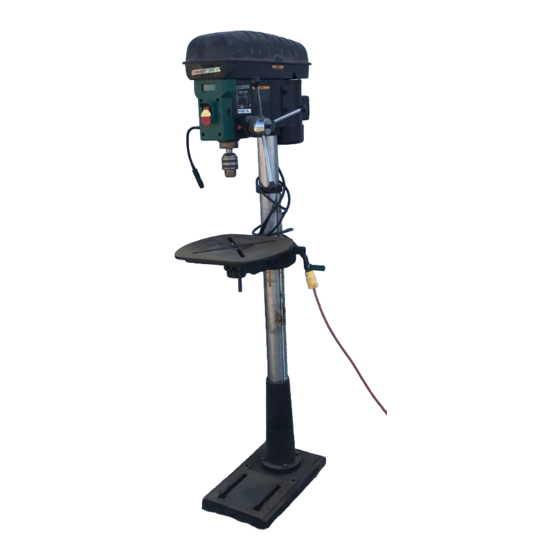
- Page 1 Model No. 240-0066 Owner’s Manual 17" VARIABLE SPEED DRILL PRESS WITH DIGITAL READOUT QUESTION... 1•877•393•7121 You will need this manual for safety instructions, operating procedures, and warranty. Put it and the original sales invoice in a safe, dry place for future reference. 10-1115...
-
Page 2: Table Of Contents
TABLE OF CONTENTS PRODUCTION SPECIFICATIONS SECTION PAGE SAFETY RULES Peak HP ........1 Variable Speed Range . -
Page 3: Safety Rules
SAFETY RULES WARNING TOOL MAINTENANCE For your own safety, read and understand all warnings • Turn the machine "OFF", and disconnect the machine and operating instructions before using any tool or from the power source prior to inspection. equipment. • Maintain all tools and machines in peak condition. Keep WARNING tools sharp and clean for best and safest performance. Some dust created by operation of power tool contains • Follow instructions for lubricating and changing chemicals known to the State of California to cause accessories. cancer, birth defects or other reproductive harm. • Check for damaged parts. Check for alignment of To reduce your exposure to these chemicals: work in a moving parts, binding, breakage, mounting and any well ventilated area and work with approved safety other condition that may affect tool's operation. equipment. Always wear OSHA/NIOSH approved, properly fitting face mask or respirator when using such • Poorly maintained tools and machines can further tools. damage the tool or machine and/or cause injury. • A guard or any other part that is damaged should be WARNING repaired or replaced. Do not perform makeshift repairs. Failure to follow these rules may result in serious personal TOOL OPERATION injury. Remember that being careless for even a fraction • Avoid accidental start-up. Make sure that the tool is in of a second can result in severe personal injury. -
Page 4: Assembly
ASSEMBLY UNPACKING Refer to Figure 1. • Check freight damage before opening the package. If freight damage is noticed, file claim with the carrier immediately. • Check to ensure all parts are present. Contact Customer Service Center at 1-877-393-7121 (M-F 9am – 5pm) immediately for missing parts. • Locate the following parts before assembling: A. Head Assembly B . Table C . Base D . Column Assembly E . Hex Bolts (4) F . Spring Washers (4) G . F eed Handles (3) H. Chuck I. Chuck Key J. Crank Handle K. Hex Wrenches (2) Figure 1 - Unpacking... -
Page 5: Install Column Support
can rotate around the column smoothly. Adjust the WARNING retaining ring if necessary. The drill press is designed to be safely assembled by at • Align and attach the crank handle to the shaft on the least two people working together. table assembly. Secure with screw. • Thread and clamp tight the table locking handle to INSTALL COLUMN SUPPORT secure the table assembly on the column. Refer to Figure 2 Figure 3 Pinion Gear • Place the base on the floor or a bench. • Place column on the base. • Align the holes and secure the column on the base with 4 long hex bolts and washers. Figure 2 Locking Bolt Crank Handle Table Alignment Pin Column Hex Bolt Figure 4 Set Screw Retaining Ring Table Assembly Bracket Locking Handle Base Table Assembly Crank Handle... -
Page 6: Mount Drill Press
Figure 5 Figure 7 Head Assembly Head Assembly Arbor Chuck Set Screws Scrap Wood Mallet INSTALL HANDLES MOUNT DRILL PRESS Refer to Figure 6 Refer to Figure 8 • Locate the three thread holes on the hub of the head. • The machine must be installed in a well-lighted area • Thread the handles into the holes of hub until tight. with correct power supply. • The machine can be installed on either a workbench or Figure 6 a tool stand by using bolts, lock washers, and hex nuts. • The machine must be bolted to a firm and level surface. • There must be enough clearance for the moving workpiece during operation. There must be enough room for safety operation of the machine. Figure 8 Feed Handles Mounting Holes INSTALL THE CHUCK Refer to Figure 7... -
Page 7: Grounding Instructions
• Power supply to the motor is controlled by a locking • The conductor with insulation having an outer surface rocker switch. Remove the key to prevent unauthorized that is green with or without yellow stripes is the use. equipment-grounding conductor. If repair or replacement of the electric cord or plug is necessary, do not connect GROUNDING INSTRUCTIONS the green (or green and yellow) wire to a live terminal. WARNING A temporary 3-prong to 2-prong grounding adapter (see Figure 10) may be used to connect this plug to a matching Improper connection of equipment grounding conductor 2-conductor receptacle as shown in figure 10. The can result in the risk of electrical shock. temporary adapter should be used only until a properly • The machine should be grounded while in use to protect grounded outlet can be installed by a qualified electrician. operator from electrical shock. • In the event of an electrical short circuit, grounding reduces the risk of electrical shock by providing an Figure 10 - 2-Prong Receptacle escape wire for the electric current. • This machine is equipped with an approved Grounded outlet Box 3-conductor cord rated at 150V and a 3-prong Grounding grounding type plug (Figure 9) for your protection Adapter Means against shock hazards. • Grounding plug should be plugged directly into a properly installed and grounded 3-prong grounding-type receptacle, as shown (Figure 9) • The plug must be plugged into an outlet that is properly installed and grounded in accordance with all local... -
Page 8: Operation
OPERATION Figure 11 - On-Off Switch WARNING For your own safety, read the entire operation manual and safety instructions before using the machine. injury. SAFETY PRECAUTIONS • Be aware of general power tool safety. Make sure all the safety rules are understood. • Disconnect the machine from power source whenever adjusting or replacing any parts. • Do not plug in unless switch is in “OFF” position. ADJUST TABLE HEIGHT AND TILT TABLE • Keep hands away from all moving parts. Refer to Figure 12 and 13 • Wear eye protection or face shield during operation. • Make sure all mobile parts move freely and are free • To raise or lower the table, loosen the table locking from interference. handle. Turn the table crank handle toward the desired • Never turn the machine “ON” with the workpiece height. Tighten locking handle. contacting the drill bit. • To rotate the table, loosen locking handle, rotate table to • Properly support long or wide workpieces. the desired position, and tighten the handle. • Turn switch off and disconnect power whenever drill • To tilt the table right or left by removing the table press is not in use. alignment pin underneath the table platform. • Keep drill press maintained. Follow maintenance. -
Page 9: Adjust Speeds
ADJUST SPEEDS Figure 15 Refer to Figure 14 WARNING To avoid damaging the drive belts and pulleys, DO NOT Chuck Key turn speed control knob unless the motor is running. Chuck Jaws The speed range is 450 RPM to 3000 RPM. To increase speed, turn the knob counterclockwise. To lower speed, Drill Bit3 turn the knob clockwise. The speed will display on the digital read-out panel. Figure 14 ADJUST DRILL DEPTH Refer to Figure 16 Two ways to adjust the drill depth to the desired height: • Loosen the lock knob. • Rotate depth gauge to the desired setting. • Retighten the lock knob securely. Digital Readout Panel The other way to adjust the drill depth to the desired height: • Turn the switch to "OFF" position. • Secure the workpiece to the drill table by using a scrap piece of wood between the workpiece and clamp to Speed avoid damage to workpiece. control knob • Lower the drill bit by turning the feed handles until the drill bit touches the workpiece. Note: This sets the depth to zero at the surface of the INSTALL DRILL BIT workpiece. -
Page 10: Maintenance
MAINTENANCE LUBRICATION WARNING • A light coat of paste wax on the work table will make it Turn the switch to the “OFF” position and disconnect the easier to feed the workpiece and prevent rust. machine from power source before servicing or disassem- bling any components. KEEP TOOL IN REPAIR • If power cord is worn, cut or damaged in any way, do CLEANING not operate the machine. • K eep machine and workplace clean. Avoid • Replace any worn, damaged, or missing parts. Use accumulation of sawdust on the tool. parts listed to order parts. • Be certain the motor is kept clean and free of dust. • Any attempt to repair motor may create a hazard unless • Use soap and water to clean painted parts, rubber parts repair is done by a qualified service technician. and plastic guards. • Call the customer line at 1-877-393-7121. -
Page 11: Troubleshooting
TROUBLESHOOTING SYMPTOM POSSIBLE CAUSE(S) SOLUTIONS Motor will not start 1. Low voltage 1. Check power supply for proper voltage 2. Short circuit in line cord or plug 2. Inspect line cord and plug for faulty insulation or shorted connection 3. Short circuit in motor 3. Inspect connection on motor. 4. Open circuit or loose connection in 4. Inspect connection on motor motor 5. Incorrect fuses or circuit breakers 5. Replace with correct fuses or circuit breakers 6. Defective switch 6. Replace switch 7. Defective capacitor 7. Replace capacitor Motor stalls or fails to 1. Power overload 1. Reduce workload on the power supply reach full speed 2. Low voltage from power supply 2. Check power supply for proper voltage 3. Undersized line cord 3. Use line cord of adequate size or reduce length of wiring 4. Motor overload 4. Reduce load on motor 5. Short circuit or loose connection in 5. Inspect the connection in motor for loose or motor shorted connection 6. Incorrect fuses or circuit breakers 6. Replace with correct fuses or circuit breakers Motor overheats Motor overloaded Reduce load on motor. Turn off the machine until motor cools down... -
Page 12: Parts Illustration & List
17” DRILL PRESS PARTS ILLUSTRATION... - Page 13 17” DRILL PRESS PARTS LIST Key No. Part No. Part Name Key No. Part No. Part Name 1 DP1700001 Bearing, 51107 67 DP1700067 Pan Head Screw, M6*10 2 DP1700002 Spindle Pulley Upper 68 DP1700068 Flat Washer, ¢6 3 DP1700003 Spindle Pulley Lower 69 DP1700069 Lower Cover 4 DP1700004 Magnet, Ø4×3 70 DP1700070 Washer 5 DP1700005...
-
Page 14: Warranty
MASTERFORCE™ 17” DRILL PRESS WARRANTY 90-DAY MONEY BACK GUARANTEE: This MASTERFORCE™ brand power tool carries our 90-DAY Money Back Guarantee. If you are not completely satisfied with your MASTERFORCE™ brand power tool for any reason within ninety (90) days from the date of purchase, return the tool with your original receipt to any MENARDS® retail store, and we will provide you a refund – no questions asked. 3-YEAR LIMITED WARRANTY: This MASTERFORCE™ brand power tool carries our famous No Hassle 3-Year Limited Warranty to the original purchaser. If, during normal use, this MASTERFORCE™ power tool breaks or fails due to a defect in material or workmanship within three (3) years from the date of original purchase, simply bring this tool with the original sales receipt back to your nearest MENARDS® retail store. At its discretion, MASTERFORCE™ agrees to have the tool or any defective part(s) repaired or replaced with the same or similar MASTERFORCE™ product or part free of charge, within the stated warranty period, when returned by the original purchaser with original sales receipt. Not withstanding the foregoing, this limited warranty does not cover any damage that has resulted from abuse or misuse of the Merchandise. This warranty: (1) excludes expendable parts including but not limited to blades, brushes, belts, bits, light bulbs, and/or batteries; (2) shall be void if this tool is used for commercial and/or rental purposes; and (3) does not cover any losses, injuries to persons/property or costs. This warranty does give you specific legal rights and you may have other rights, which vary from state to state. Be careful, tools are dangerous if improperly used or maintained. Seller’s employees are not qualified to advise you on the use of this Merchandise. Any oral representation(s) made will not be binding on seller or its employees. The rights under this limited warranty are to the original purchaser of the Merchandise and may not be transferred to any subsequent owner. This limited warranty is in lieu of all warranties, expressed or implied including warranties or merchantability and fitness for a particular purpose. Seller shall not be liable for any special, incidental, or consequential damages. The sole exclusive remedy against the seller will be for the replacement of any defects as provided herein, as long as the seller is willing or able to replace this product or is willing to refund the purchase price as provided above. For insurance purposes, seller is not allowed to demonstrate any of these power tools for you. For questions / comments, technical assistance or repair parts – Please Call Toll Free at: 1-877-393-7121 (M-F 9am – 5pm) SAVE YOUR RECEIPTS. THIS WARRANTY IS VOID WITHOUT THEM. - Page 15 NOTE...
- Page 16 Menard, Inc. Eau Claire, WI 54703...
Need help?
Do you have a question about the 240-0066 and is the answer not in the manual?
Questions and answers