Table of Contents

Related Manuals for TEXAS RANGER TR-936

Summary of Contents for TEXAS RANGER TR-936
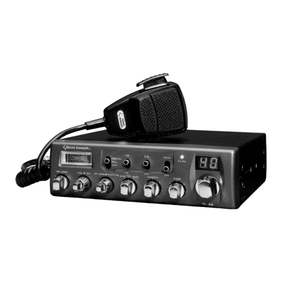
- Page 1 TR-936 401 W. 35th Street, Suite B National City , CA 91950 (800)446-5778. FAX( 619)426-3788 Email : rci@rangerusa.com http : //www.rangerusa.com SOLID STATE CITIZENS BAND AM MOBILE TRANSCEIVE R OWNER’S MANUAL Printed In Malaysia AT6960A11A PD000619...
-
Page 2: Table Of Contents
TABLE OF CONTENTS CHAPTER 1 SPECIFICATIONS PAGE GENERAL CHAPTER 1 Frequency Range 26.965 - 27.405 MHz Specifications ........Emission Frequency Control Phase-Lock-Loop (PLL) Synthesizer... -
Page 3: Ignition Noise Interference
IGNITION NOISE INTERFERENCE CHAPTER 2 INSTALLATION Use of a mobile receiver at low signal levels is normally limited by the presence of electrical noise. The primary source of noise in automobile LOCATION installations is from the generator and ignition system in the vehicle. Under Plan the location of the transceiver and microphone bracket before starting the most operating conditions, when signal level is adequate, the background noise installation. -
Page 4: Tuning The Antenna For Optimum Swr
TUNING THE ANTENNA FOR OPTIMUM SWR If your are having difficulties in adjusting your antenna, check the followings : Since there is such a wide variety of base and mobile antennas, this section will strictly concern itself to the various types of mobile adjustable antennas. a. -
Page 5: Public Address
6. S-RF/CAL/SWR SWITCH : In the S-RF position, the meter will indicate CHAPTER 3 OPERATION the strength of the signal being received, as well as the relative RF output of transmission. When calibrating the SWR meter, you need to put this switch FRONT PANEL in the CAL position. -
Page 6: External Speaker
16. CHANNEL DISPLAY : The channel display indicates the current FREQUENCY CHART selected channel. Channel Channel Frequency Channel Channel Frequency REAR PANEL 26.965 MHz 27.215 MHz 26.975 MHz 27.225 MHz 26.985 MHz 27.255 MHz 27.005 MHz 27.235 MHz This device complies with part 15 of the FCC Rules. Operation is subject to the condition that this device does not cause harmful interference. -
Page 7: Procedure To Receive And Transmit
PROCEDURE TO RECEIVE AND TRANSMIT ALTERNATE MICROPHONES AND INSTALLATION A. MICROPHONE For best results, the user should select a low-impedance dynamic type microphone or a transistorized microphone. Transistorized type microphones The receiver and transmitter are controlled by the push-to-talk switch on the have a low output impedance characteristics. -
Page 8: Limited Warranty
2. In the event of a defect during the warranty period, Ranger shall, at its option, repair or replace the defective product, or refund the purchase price of product. Such action shall constitute the purchaser's exclusive remedy under this warranty.
Need help?
Do you have a question about the TR-936 and is the answer not in the manual?
Questions and answers