Advertisement
Advertisement
Table of Contents

Summary of Contents for Gemini SP-1
- Page 2 Page 2...
- Page 3 Front Left Speaker Rear Right Speaker Front Right Speaker Subwoofer Rear Left Speaker Two Channel Stereo Configuration Two Channel Four Speaker Stereo Configuration DANCE FLOOR DANCE FLOOR Two Channel Four Speaker Stereo Circle Surround Configuration Diagonal Configuration DANCE FLOOR DANCE FLOOR Page 3...
-
Page 4: Speaker Placement
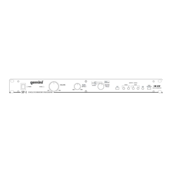
You can also readjust the rear levels for music with varying spatial information. 4. The SP-1 is supplied with 5 BALANCED OUTPUTS (1, 2, 3, 5, 6). The BALANCED OUTPUT connectors are used to connect to your 3. Sound Field: Use the SOUND FIELD (15) control to choose a mode of amplifiers using standard XLR cables. -
Page 5: Specifications
Rear Channel Effect Max./Min. Ratio..........12 dB Printed Circuit Boards Power Source............115V/230V, 60 Hz/50 Hz Item # Description Part # PRINTED CIRCUIT BOARD SP-1-1 262-241 Power Consumption................10 W PRINTED CIRCUIT BOARD SP-1-2 262-242 Dimensions.......19” x 1.75” x 10.5” (483 x 44 x 266 mm) - Page 6 Parts Lists - Main PCB Description Part # Item # Designators INTEGRATED CIRCUIT LB1403N 074-022 IC2-3,IC12-15 INTEGRATED CIRCUIT 4558DD 074-163 (BA15218,M5218A) INTEGRATED CIRCUIT TL072CP 074-168 INTEGRATED CIRCUIT SSM2005RS-REEL 074-172 INTEGRATED CIRCUIT PIC16C505-04/P 074-171 INTEGRATED CIRCUIT NJM78L05A 074-173 INTEGRATED CIRCUIT NJM78L06A 074-174 INTEGRATED CIRCUIT NJM79L06A 074-175...
- Page 7 Main PCB Page 6...
- Page 8 Input/Output PCB Page 7...
-
Page 9: Switch Pcb
Switch PCB Page 8... - Page 10 Schematic INPUT/OUTPUT PCB 2SC2878 C19 10uF25V R56 270 R51 33 R60 10K1% R54 4.7K +15V XLR7 0.047uF 10K1% C23 10uF25V R61 270 R57 33 IC4A R554.7k NJM4558DD -15V 0.047uF 2SC2878 2SC2878 C10 10uF25V R14 270 R16 33 R15 10K1% R12 4.7K +15V 0.047uF MAIN PCB...
Need help?
Do you have a question about the SP-1 and is the answer not in the manual?
Questions and answers