Table of Contents
Advertisement
Advertisement
Table of Contents

Summary of Contents for Futada 4PK Super R
- Page 1 NSTRUCTION ANUAL 1M23N20723...
- Page 2 Thank you for purchasing a Futaba 4PK Super R-2.4GHz system. Before using your 4PK Super R-2.4GHz system, read this manual carefully in order to use your R/C set safely. After reading this manual, store it in a safe place. Application, Export, and Modification 1.
- Page 3 Battery Recycling (for U.S.A.) ™ The RBRC SEAL on the (easily removable) nickel-cadmium battery and nickel-metal-hydride battery contained in Futaba products indicates that Futaba Corporation of America is voluntarily participating in an in- dustry program to collect and recycle these batteries at the end of their useful lives, when taken out of service within the United States.
-
Page 4: Table Of Contents
Table Of Contents For Your Safety As Well As That Of Others ......8 Explanation of Symbols ..............8 2.4GHz System Precautions ............8 High Speed Mode Precautions .............8 Operation Precautions ..............9 Ni-MH/Ni-Cd Battery Handling Precautions ......10 Storage and Disposal Precautions ..........11 Other Precautions ...............11 Before Using ..............12 Features ..................12 Set Contents ................14... - Page 5 Installation ................31 Receiver and Servo Connections ..........31 Installation Safety Precautions ..........32 For Your Safety As Well As That Of Others Initial Set-Up ...............35 Preparations (Transmitter) ............35 Before Using Function Map ..............38 Menu Selection ................38 Function Menu Screen .............38 Menu Screen ................39 Installation Custom Menu ................40 Direct Selection ................42...
- Page 6 Start Function / Engine Cut "START" ........66 Throttle preset at start function/ engine cut off by switch A.B.S. Function "A.B.S" .............69 Pulse brake Brake Mixing "BRAKE" ..............74 Front and rear independent brake control for 1/5GP car, etc. Boat Mode "BOAT" ..............78 Boat, etc.
- Page 7 System Functions "SYSTM" ............122 Battery type setting Liquid crystal screen backlighting display mode setup Setting of ON time For Your Safety Liquid crystal screen contrast adjustment As Well As Buzzer sound tone adjustment That Of Others Pilot lamp display color setup Initial screen display mode setting Second condition setting The power off forgotten alarm setting...
-
Page 8: For Your Safety As Well As That Of Others
For Your Safety As Well As That Of Others Use this product in a safe manner. Please observe the following safety precautions at all times. Explanation of Symbols The parts of this manual indicated by the following symbols are extremely important and must be observed. -
Page 9: Operation Precautions
Operation Precautions Warning Do not operate outdoors on rainy days, run through puddles of water or use when visibility is limited. Should any type of moisture (water or snow) enter any component of the system, erratic operation and loss of control may occur. -
Page 10: Ni-Mh/Ni-Cd Battery Handling Precautions
Caution (Fail safe function) Before running (cruising), check the fail safe function. Check Method; Before starting the engine, check the fail safe function as follows: 1) Turn on the transmitter and receiver power switches. 2) Wait at least one minute, then turn off the transmitter power switch. (The transmitter automatically transfers the fail safe data to the receiver every minute.) 3) Check if the fail safe function moves the servos to the preset position when reception fails. -
Page 11: Storage And Disposal Precautions
Always keep the charger disconnected from the outlet while it is not in use. Storage and Disposal Precautions Warning Do not leave the radio system or models within the reach of small children. A small child may accidentally operate the system. This could cause a dangerous situation and injuries. Ni-Cd batteries can be very dangerous when mishandled and cause chemical damage. -
Page 12: Before Using
Before Using Features -2.4GHzSS (Spread Spectrum) radio communication system Frequency channel setting is unnecessary: Channel shifting takes place within the 2.4GHz band automatically. This system minimizes the interference from other 2.4GHz systems. -Model memory for 40 models Model names can use up to 10 letters, numbers, and symbols, so that logical names may be used. - Page 13 throttle operates normally again. -Steering speed (STSPD) When you sense that the steering servo is too fast, etc., the servo operating speed (direction that suppresses the maximum speed) can be adjusted. -Racing timer (TIMER) The lap timer can record 99 lap times, total time, and average lap time. The timer can also be started automatically by trigger operation.
-
Page 14: Set Contents
Set Contents depend on the set as shown below. T4PKSR Transmitter Receiver R614FS or R614FF-E Transmitter Ni-MH battery pack HT5F1700B *Installed in transmitter. Receiver switch Miscellaneous Wheel offset adapter(APA) Wheel adapter 32deg Hook Instruction manual - If any of the set contents are missing, or you have any questions, please contact your dealer. -
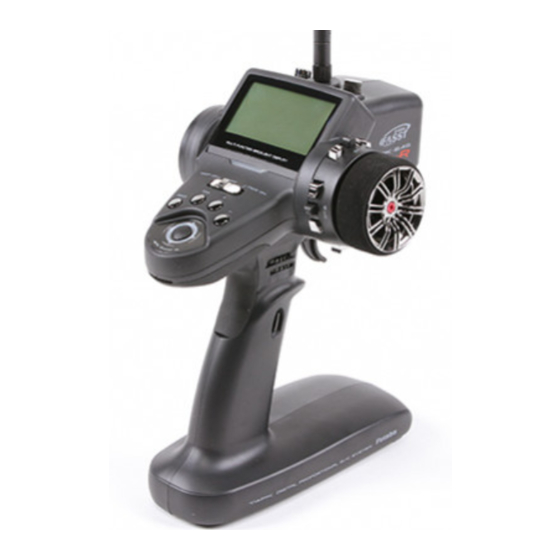
Page 15: Transmittert4Pksr
Transmitter T4PKSR Nomenclature Antenna Push switch 3 (PS3) Digital Dial 3 (DL3) LCD screen Digital Trim1 (DT1) (default steering trim) Steering wheel Power&Display switch Edit buttons Digital Trim 2 (DT2) (default throttle trim) Digital Dial 1 (DL1) (default dual rate) Push switch 2 (PS2) Digital Dial 2 (DL2) (default ATL) -
Page 16: Power & Display Switch
Power & Display Switch The power switch and display switch of the T4PKSR are integrated. In the PWR ON mode, radio waves are transmitted and in the DISP ON mode, model data, settings can be checked without transmitting radio waves. PWR ON Radio waves are being transmitted... -
Page 17: Digital Trim Operation
Digital Trim Operation (Initial settings: DT1: Steering trim, DT2: Throttle trim, DT3: -------) Digital trims can be used in 2 ways: Operating by the lever: Push the lever to the left or right (up or down). Operating by push button switch: Press the push button switch in the desired direction. The current position is displayed on the LCD screen in the bottom three rows of the list. -
Page 18: Mechanical Atl Adjustment
Mechanical ATL Adjustment Make this adjustment when you want to decrease the stroke of the brake (back) side of the throttle trigger for operation feel. Adjustment brake (reverse) stroke. (The screw moves the throttle trigger stopper.) Mechanical ATL adjusting screw Note: Once you have changed the mechanical stroke on the brake side, be sure to adjust the scale of the throttle channel accordingly by using the "Adjuster Function"... -
Page 19: Trigger Slide Adjustment
Trigger Slide Adjustment The throttle trigger position can be moved forward and backward. Adjustment Using a 2. trigger slide mounting screw by turning it slightly counterclockwise. Adjust so that the bottom Trigger slide Using a 2. mark does not exceed mounting screw the top marking line. -
Page 20: Charging The Ht5F1700B Battery
Charging The HT5F1700B Battery AC outlet Charging Plug the transmitter cord of the special char- Charger transmitter. Plug the charger into an AC outlet. Transmitter charging Check that the charging LED lights. When charging the HT5F1700B battery with the special char- ger, allow about 15 hours for charging. -
Page 21: Grip Vibrator
Grip Vibrator A vibrator is built into the grip of the T4PKSR. The vibrator vibrates at racing timer lap navigation, time-up, and low battery alarm. (p.130) Display when power switch is turned on Power switch turned on initial screen shown below appears. Battery voltage display Edit button lock display Total timer display (H:M) -
Page 22: Edit Button Lock And Trim/Dial Lock
Edit button lock and trim/dial lock T4PKSR setup and operation by edit button (p.15) and digital trim DT1, DT2, and DT3 and dials DL1, DL2, and DL3 can be prohibited. Setting Edit button lock: When the (+) button is pressed for about 1 second at the initial screen, a confirmation beep is generated and the edit button lock display appears on the screen. -
Page 23: Changing Wheel Position And Modifying For Left-Hand Use
Changing wheel position and modifying for left-hand use Changing the wheel position Modifying for left-hand use The wheel position can be offset by using the The wheel section left and right installa- accessory APA wheel position offset adapter. tion direction can be reversed. Angle can be adjusted The operating angle of the wheel can be adjusted The operating angle of the wheel can be changed from 34 deg to 32 deg by installing... - Page 24 Remove the steering wheel unit. Disconnect the steering wheel unit connector. Wheel unit Installing the accessory APA steering wheel offset adapter original screws. The steering wheel unit connector through the adapter. Adapter APA Install the steering wheel unit us- Unit mounting screws ing the 3 mounting screws.
- Page 25 Pull out the wiring as far as possible from between the wheel unit and APA. Stow the surplus pulled out wiring in the transmitter. Stow the surplus wiring here. Install the assembled wheel unit and APA to the transmitter using the screw supplied. The APA mounting screws are in the hook and APA mounting screws bag.
- Page 26 Modifying for left-hand use Remove the wheel section rear cover. serting a coin, etc. into the slot at the bottom of the rear cover. Push in the disconnected connector so that it can be connected at the opposite side. At the opposite side, connect the steering wheel unit connector and install the steering wheel unit, steering wheel cover, and wheel to...
-
Page 27: Installing The Accessory Neck Strap Hook
Installing the accessory neck strap hook A hook can be installed to the T4PKSR, as required. The hook is in the hook and APA mounting screws bag supplied with the set. Pull up the bottom of the grip rub- ber as shown in the figure. Grip rubber Pull out the grip rubber in the arrow direction. -
Page 28: About Transmitter Antenna And Receiver
About Transmitter Antenna and Receiver About The Transmitter Antenna Antenna cally to the ground. Antenna Moving Range Warning Otherwise, the operating range may become shorter. Never hold only the antenna. Hold the grip handle. Otherwise, the antenna may be damaged. The antenna position can be changed in the range as shown in figures A and B. -
Page 29: Receiver Nomenclature
Receiver Terminology Tactile switch/LED Connectors Antenna :CH4 servo(CH4) :CH3 servo(CH3) :Throttle servo(CH2) :Steering servo(CH1) :Power connector/DSC connector How to link the transmitter and the receiver Each transmitter has an individually assigned, unique ID code. In order to start opera- tion, the receiver must be linked with the ID code of the transmitter to which it is being paired. -
Page 30: Receiver Installation
Receiver Installation Install the R614FS receiver on the car as follows: The operating range may become shorter, depending on where the receiver and the an- tenna are mounted. WARNING Antenna Do not cut or bundle the receiver antenna wire. tube Antenna Install the antenna in the higher place as shown in the figure. -
Page 31: Installation
Installation Receiver and Servo Connections Connect the receiver and servos as shown below. Connect and install the receiver and servos in accordance with "Installation Safety Precautions" on the next page. troller and servos separately. The receiver also depends on the set. When using the DSC cord with a gasoline engine car, connect the optional double ex- tension cord to B/C of the receiver and the DSC cord and receiver switch to the opposite side connector. -
Page 32: Installation Safety Precautions
Installation Safety Precautions Warning Receiver (receiver antenna) Do not cut or bundle the receiver antenna wire. Do not bundle the receiver antenna wire together with the motor controller lead wire. Keep the receiver antenna wire at least 1cm away from motor, battery, and other wiring carrying heavy current. Do not use a metal receiver antenna holder on a plate made of metal, carbon, or other conductive material. -
Page 33: Servo Installation
Warning Connector Connections Be sure the receiver, servo, battery and connectors are fully and firmly connected. If vibration from the model causes a connector to work loose while the model is in operation, you may lose control . Servo Installation When you install the servos, always use the rubber grommets provided in servo hardware bags. - Page 34 Warning Electronic Speed Control Install the heat sinks where they will not come in contact with aluminum, carbon fiber or other parts that conduct electricity. If the FET Amp (Electronic speed control) heat sinks touch other materials that conduct electricity a short circuit could occur.
-
Page 35: Initial Set-Up
Initial Set-Up Preparations (Transmitter) Before setting the Transmitter functions, check and set items 1 to 5 below. (Display when power switch turned on) When the power switch is turned on, the currently selected model number is displayed. Check if this number is the model number you want to set-up. To change the model number, use the Model Select function (p.108). -
Page 36: Using
3. Servo Response Mode Check Check that the servo response setting matches the servo be- ing used. When using a digital servo (including BLS Series brushless servo), both HIGH SPEED and NORMAL can be used. When an analog servo is used, HIGH SPEED cannot be used;... -
Page 37: Before
Steering dual rate - Steering dual rate (DL1) check At initial set-up, steering dual rate (D/R) is assigned to DL1 dial, at the grip of the transmitter. Operate the DL1 and check if the D/R value displayed on the screen changes. Af- ter checking ST.D/R, set the steering dual rate to 100%. -
Page 38: Function Map
Function Map Menu Selection The function set-up screen can be easily selected from the function menu displayed on the LCD screen. The function menu can be selected from among the following 4 types to match the level of use. To select the type, use the Menu type select function (p.113). -Level 1 (LEVEL1) : Basic functions only -Level 2 (LEVEL2) : For middle class driver -Big car (BIGCAR) : Displays the main functions for large cars (1/5). -
Page 39: Menu Screen
Menu Screen The menu screen displays 18 items on 3 rows and 6 lines on one page and displays up to A menu screen matched to the When the cursor is in a position without purpose can also be created by a function assigned, "OF"... -
Page 40: Custom Menu
Custom Menu A menu matched to the purpose (custom menu) can be created by using the menu cus- tomize function. A different menu can be created for each model memory. In addition, custom menus can be copied to other models by using menu copy of the model copy function (p.110). - Page 41 Customizing all functions. In addition to the menu types shown page 38, there is ALL- OFF. It is convenient when customizing all functions. (Opening Screen) Call the menu screen from the initial screen by (JOG) button up, down, left, or right operation. On the MENU1 screen, move the cursor to "*MENU-T"...
-
Page 42: Direct Selection
Direct Selection Button" (DIR) function. Initial Setting Direct Function ab- Button Function breviation Channel End Point Adjuster Press STSPD STEXP SUBTR Press THEXP THSPD M-SEL Press 2,3,4,5,6 A.B.S Press Call the direct Selection Upon your needs, select one of the 8 functions and then click its button screen by pressing the to call the Function Set-up Screen. - Page 43 Direct Customize the edit buttons by using the direct customize function. Direct call lets you create a different menu for each model memory. Direct call assigned to each edit button can also be copied to other models by using menu copy of the model copy function (p.110). Direct selection function assignment The setup screen of this function is called by pressing the (Opening Screen)
-
Page 44: List Of Functions By Menu Type
List of functions by menu type Function LEVEL1 LEVEL2 BIGCAR LEVEL3 Function abbreviation (Initial setting) STEXP STSPD THEXP THSPD A.B.S ACCEL START BRAKE IDLUP TIMER LAP-L P-MIX S-MIX BOAT SUBTR * M-SEL * M-RES M-COP NAME DIAL SWTCH CH3/4 RXSYS * MENU-T SYSTM DTTRN... -
Page 45: Functions List
Function list Function Page Function Description of function abbreviation P-49 End point adjustment STEXP P-56 STSPD P-61 THEXP P-57 Throttle curve adjustment THSPD P-63 Throttle servo delay A.B.S P-69 Pumping brake ACCEL P-52 Function which adjusts the rise characteristic from the throttle neutral position START P-66 Throttle preset at start function/ engine cut off by switch... -
Page 46: Functions
Function Receiver Type / Servo Response Mode "RXSYS" Receiver There are two types of Futaba 2.4GHz FASST receivers for cars depending on the sys- tem differences: C1 type and C2 type. The R603FS/FF are C1 type and the R614FS / FF-E supplied with the 4PKSR set as standard is C2 type. -
Page 47: Servo Reverse "Rev
Servo Reverse "REV" (All channel) This function reverses the direction of operation of the servos related to transmitter steering, throttle, channel 3, and channel 4 operation. However, when the position set by trim or subtrim shifts from the center, the center becomes the opposite side. Calling the setup screen *Calling from menu screen button... -
Page 48: Servo Operation Reversing Subtrim "Subtr
(All channel) Use this function to adjust the neutral position of the steering, throttle, channel 3 and channel 4 servos. 90deg Calling the setup screen *Calling from menu screen button (Opening Screen) * b l i n k s a t t h e c u r r e n t Channel Menu screen call button... -
Page 49: Servo Center Position Fine Adjustment End Point Adjuster "Epa
(All channel) Use this when performing left and right end point adjustments, throttle high side/ brake side operation amount adjustment, channel 3 and channel 4 servo up side/ down side operation amount adjustment during linkage. - Correct the maximum steering angle for left and right steering angles when there is a difference in the turning radius due to the characteristics, etc. - Page 50 Calling the setup screen Setting item (channel and direction) *Calling from menu screen button (Opening Screen) * b l i n k s a t t h e c u r r e n t Menu screen call button TH-BRK :Throttle (brake side) MENU 1 MENU1/2 selection button...
- Page 51 Throttle (EPA) adjustment (Preparation) Adjust button - Use the (+) and (-) buttons to - Please see previous note on Throttle EPA If "CUT OFF", (which prohibits trigger brake side operation in the boat mode (p.78) ), is set, throttle "TH-BRK" (brake side) cannot be adjusted. 3rd &...
-
Page 52: Throttle Acceleration "Accel
Throttle Acceleration "ACCEL" (Throttle system) The servo will jump to the input position at its maximum possible speed. Unlike expo- nential, which adjusts the whole throttle movement into a curve, throttle acceleration simply "jumps" away from neutral and then leaves the remaining response linear. Operation - Operation near the throt- tle trigger neutral position... - Page 53 Throttle acceleration adjustment Adjust button (Preparation) Forward acceleration amount (FWRD) Brake side acceleration amount (BRAK) 3rd/4th channel brake side acceleration amount (BRAK 3CH),(BRAK 4CH) Caution When "TRG-BRK" is set to "CUT OFF" by boat mode function (p.78), the brake side function is not activated.
-
Page 54: Fail Safe/Battery Fail Safe Function "F/S
Fail Safe/Battery Fail Safe Function "F/S" (All channel) Fail Safe Mode (F/S) This function moves each servo to a preset position when the receiver cannot receive the signals from the transmitter for some reason. -When "Rx Type"(p.46) is set "FASST-C1" and "Servo Response"(p.46) is "NORMAL", the setting fail safe (F/S) is only throttle (TH). - Page 55 Fail safe mode selection Setup item selection (Preparation) F/S mode selection (Mode selection) (Each channel can be individually F/S mode OFF, HOLD, F/S Fail safe function setup F/S position setup button (Servo position setup) - The (+) and (-) buttons are W h e n R X T Y P E i s s e t t o "FASST-C1", the BATT-F/S func- Battery fail safe function ON/OFF &...
-
Page 56: Steering Exponential "Stexp
(Steering system) This function is used to change the sensitivity of the steering servo around the neutral position. It has no effect on the maximum servo travel. Racers Tip When the setting is not determined, or the characteristics of the model are unknown, start with 0%. -
Page 57: Steering Operation Curve Adjustment Throttle Exponential "Thexp
Throttle EXP "THEXP" (Throttle system) This function makes the throttle high side and brake side direction servo operation quicker or milder. It has no effect on the servo maximum operation amount. For the high side, selection from among three kinds of curves (EXP/VTR/CRV) is also possible. - Page 58 Adjustment method for EXP curve (Preparation) Curve type Select button Setup items selection BRK-EXP :Brake side rate Setup item selection Quick for a faster throttle response or use Adjustment range FWD-TYP :EXP, VTR, CRV Mild Adjust button Quick for a faster brake response or use Mild Throttle EXP "THEXP"...
- Page 59 Adjustment method for VTR curve (Preparation) Curve type Select button Setup items Switching point A ve r t i c a l c u r s o r l i n e t h a t point point is displayed on the setup selection BRK-EXP :Brake side rate Setup item selection...
-
Page 60: Throttle Curve Adjustment
Adjustment method for VTR curve (Preparation) Curve type Select button Point in current setup Setup items A ve r t i c a l c u r s o r l i n e t h a t C:RES :Curve reset setup is displayed on the setup selection BRK-EXP :Brake side rate... -
Page 61: Steering Speed "Stspd
(Steering system) Quick steering operation will cause momentary understeering, loss of speed, or spinning. This function is effective in such cases. Spin Without "STSPD" With "STSPD" Operation - This function limits the maximum speed of the steering servo. (Delay function) - T he st e e r i ng s p e e d whe n the steering wheel is operated (TURN direction) and returned... - Page 62 Steering Speed adjustment Setup item selection (Preparation) Adjustment range 100% Servo operation is delayed. Adjust button Setting example (Steering servo: BLS451 / BLS351) . . . (Setting criteria) - Onroad TURN side: Approx. 50~80% RETURN side: Approx. 60~100% - Offroad TURN side: Approx. 70~100% RETURN side: Approx. 80~100% Dial / Trim Setting The steering speed adjustment "TURN"...
-
Page 63: Throttle Speed "Thspd
Throttle Speed "THSPD" (Throttle system) Sudden throttle trigger operation on a slippery road only causes the wheels to spin and the ve- hicle cannot accelerate smoothly. Setting the throttle speed function reduces wasteful battery consumption while at the same time permitting smooth, enjoyable operation. - Page 64 Adjustment method for 1 SPEED (Preparation) Speed type Select button Setting item MODE :Speed type selection When a value of 99 or less is Setup item selection Adjustment range Adjust button Adjustment method for 2 SPEED (Preparation) Speed type Select button Setting item MODE :Speed type selection When a value of 99 or less is set...
- Page 65 Adjustment method for 3 SPEED Speed type Select button (Preparation) When a value of 99 or less is set at either LOW or HIGH, the dis- Setting item MODE :Speed type selection Setup item selection Adjustment range Adjust button - Return to the initial value by Initial value Dial / Trim Setting The throttle speed adjustment "LOW"...
-
Page 66: Start Function / Engine Cut "Start
(Throttle system) If the track is slippery and you begin to accelerate by pushing the trigger to full throttle, the car wheels will spin and the car will not accelerate smoothly. When the Start func- tion is activated, merely operating the throttle trigger slowly causes the throttle servo to automatically switch from the set throttle position to a preset point so that the tires do not lose their grip and the car accelerates smoothly. - Page 67 Start function adjustment Setup item selection HI side, and the trigger position Setup items Adjust button Setup item selection Trigger position (TG.P) Preset position (PRST) Setting Example: (When ESC used with an electric car) READY setting (ATS) When ending setting, return to the initial screen by pressing -If the throttle trigger is moved to the set position while "READY"...
- Page 68 Engine Cut function adjustment Setup item selection Setup items Setup item selection Adjust button Preset position (PRST) When ending setting, return to the initial screen by pressing When TRG-BRK is set to CUT OFF by boat mode function When "CUT OFF", which prohibits trigger brake side operation, is set in the boat mode (p.78), "TH-BRK"...
-
Page 69: Throttle Preset At Start Function/ Engine Cut Off By Switch A.b.s. Function "A.b.s
(Throttle system) When the brakes are applied while cornering with a 4 Wheel Drive or other type of vehicle, understeer may occur. The gen- eration of understeer can be eliminated and corners can be smoothly cleared by using this function. Operation Without A.B.S. - Page 70 - ABP : Amount of brake return A.B.S Sets the rate at which the ser- DTY (duty): X and Y ratio Y: (Brake return time) vo returns versus trigger oper- X: (Brake application time) ation for brake release. When set to 0%, the ABS function TGP Trigger point) (Amount of is not performed.
- Page 71 A.B.S. function adjustment Setup item selection Adjustment buttons Function ON/OFF Brake return amount (ABP) (Amount of brake return) Delay amount (DLY) Cycle speed (CYC) CYC (Cycle) Trigger point (TGP) Trigger point) Neutral...
- Page 72 Duty ratio (DTY) Y: (Brake return time X: (Brake application time) DTY (duty): X and Y ratio Steering mixing (STM) steering operation enters the set Steering operation When ending setting, return to the initial screen by pressing Switch setting Use PS1, PS2, PS3 to switch the A.B.S. function ON/OFF. See the function select switch function (p.96).
- Page 73 Fail Safe Unit When the T4PKSR is used with the Futaba fail safe unit (FSU-1), it will operate as de- scribed below. - When the FSU-1 is connected to the throttle channel, and the A.B.S. function has for this is that the FSU-1 responds to sudden data changes caused by A.B.S. function pumping operation.
-
Page 74: Pulse Brake Brake Mixing "Brake
(Throttle, 3rd channel system) This function is used when the front and rear brakes must be adjusted independently such as a 1/5 scale GP car. This mixing uses the 2nd CH for the rear brakes and the 3rd or 4th CH for the front brakes, or controls the front brakes with the 3rd CH and 4th CH servos, or controls the 2nd CH by independent throttle and controls the rear and front brakes with the 3rd CH and 4th CH. - Page 75 Calling the setup screen *Calling from menu screen button (Opening Screen) * b l i n k s a t t h e c u r r e n t Menu screen call button MENU 1 MENU1/2 selection button ecuted and the screen display MENU 2 Select the function button...
- Page 76 Brake mixing adjustment Setup item selection Adjustment buttons Function ON/OFF (MDE) Brake rate (RATE) Brake EXP rate (EXP) Delay amount (DLY)
- Page 77 Brake rate (STM-LFT/STM-RGT) Function ON/OFF (ABS-MODE) Brake return amount (ABS-ABP) Delay amount (ABS-DLY) When ending setting, return to the initial screen by pressing Dial / Trim Setting The function select dial function can control the 3rd/4th channels brake rate (RATE), delay amount (DLY), and 3rd channel brake-A.B.S return amount (ABP) ...etc setting using button trim DL1, DL2, DL3 or digital trim DT3 etc.
-
Page 78: Boat Mode "Boat
(Steering, Throttle system) Shutting off brake side operation When brake side operation is unnecessary with a boat, etc., it can be shut off. Tilt mixing Tilt mixing uses an outboard engine and applies bidirectional mixing from rudder (steering) to channel 3 and from channel 3 to rudder so that with a boat, rudder opera- tion and tilt mixing operation can be performed by 2 servos. - Page 79 Tilt mixing adjustment Adjustment buttons Function ON/OFF (MODE) Mixing amount (CH1>3) Mixing amount (CH3>1) When ending setting, return to the initial screen by pressing Slave channel output (Initial value) Steering > 3rd channel side : +100% 3rd channel > Steering side : -100% Dial / Trim Setting The mixing rate amount can be controlled with digital dial DL1, DL2, DL3 or digital...
-
Page 80: Throttle Mode "Thmod
(Throttle system) -The neutral brake function is a function switch function (p.96), and setting the neutral brake function ON/OFF switch is necessary. Neutral brake, which applies the brakes at the throttle trigger neutral position, can be set. However, for Futaba speed controller (ESC) MC960CR, MC950CR, MC851C, MC602C, will not enter the operation mode to prevent the motor from rotating instantly when the power is turned on. -
Page 81: Neutral Brake Function
Neutral Brake function adjustment When ending setting, return to the initial screen by pressing Reference The ESC neutral brake function and T4PKSR neutral brake function can be used si- only one neutral brake function be used. Dial / Trim Setting When the neutral brake function is ON , the neutral brake rate (RATE) adjustment is automatically assigned to the throttle trim (DT1, 2, 3 or DL1, 2, 3). -
Page 82: Throttle Servo Forward And Brake Operation Proportion Setting
(Throttle system) This is a function select switch function. The idle-up function ON/OFF switch must be set. (p.96) It is used to improve engine starting performance by raising the idling speed when the engine of a gasoline car (boat) is started. This function is also effective when you want to prevent braking when the power was turned off during running due to the effect of gear ratio setting and the motor used with a motor car. -
Page 83: Programmable Mixes 1/2 "P-Mix
(All channels) These functions allow you to apply mixing between the steering, throttle, channel 3 and channel 4. Two programmable mixing systems can be used. The programmable mixing 1 and pro- grammable mixing 2 set-up screens are independent. Additional Functions -When the steering or throttle channel is the master channel (channel that applies mix- ing), trim data can be added. - Page 84 Program mixing adjustment Switch Setup item selection Function ON/OFF (MODE) Channel selection (MST) Channel selection (SLV) right operation, and select the slave channel by pressing the Mixing amount Mixing amount Offset amount (OFS)
- Page 85 Mixing mode (MXD) Trim mode (TRM) When ending setting, return to the initial screen by pressing When Steering and Throttle Travel is Insufficient When the steering servo travel is insufficient even when D/R is 100% and EPA is 120%, programmable mixing can be used to increase the travel somewhat. (Reference data) - PROG NIX1->ON - MST (master channel) ->...
-
Page 86: Programmable Mixes Between Arbitrary Channels Special Mixing "S-Mix
(Steering,Throttle,3rd,4th channel system) Four wheel steering 4WS mixing used with Corolla, etc., dual ESC mixing that controls the front and rear motor controllers independently, gyros which allow adjustment of the sensitivity of the Futaba car rate gyro from the transmitter, CPS-1 mixing that controls the Futaba CPS-1 power switch, and other special mixing functions can be set by special mixing (S-MIX) function. - Page 87 Calling the setup screen *Calling from menu screen button (Opening Screen) * b l i n k s a t t h e c u r r e n t Menu screen call button MENU 1 MENU1/2 selection button MENU 2 Select the function button Press t...
-
Page 88: 4Ws Mixing "Aws Mix
4WS Mixing "4WS MIX" This function can be used with crawlers and other 4WS type vehicles. It is mixing that uses the 1st CH to control front side steering and the 3rd CH to control rear side steer- ing. OFF (front side only), reverse phase, same phase, rear side only, and other 4WS type switching is used by selecting PS1 or PS2 with the function select function (p.96). - Page 89 4WS mixing adjustment Function ON/OFF (MODE) Rear rate (RATE) Mixing mode (MXMD) To end setting, return to the opening screen by pressing the Dial / Trim Setting The mixing amount can be adjusted by using the function dial function (p.98).
-
Page 90: Dual Esc Mixing "Dual Esc
Dual ESC Mixing "DUAL ESC" This function is mixing used with crawlers and other 4WD type vehicles and uses the 2nd CH to control the front motor controller and the 4th CH to control the rear motor controller. The switch which switches drive among front side only, rear side only, and both front side and rear side (4WD) is set from among DT1, 2, 3, 4, DL1, 2, 3 by the function dial function (p.98). - Page 91 Front (ERNT) / Rear (REAR) Mixing mode (MXD) Trim mode (TRM) To end setting, return to the opening screen by pressing the Dial / Trim Setting The function select dial function can control the 2nd CH ESC (Front side) rate (FRNT) 4th CH ESC (Rear side) rate (REAR) with digital dial or digital trim, using the func- tion select dial function (p.98).
-
Page 92: Gyro Mixing "Ryro Mix
Gyro Mixing "GYRO MIX" This function is a remote gain function which adjusts the sensitivity of the Futaba car rate gyro at the T4PKSR side, and is mixing that uses the 3rd CH to adjust the gyro sen- sitivity. When using the 4PKRS by switching the AVCS and normal modes use PS1, PS2 or PS3 with the function select switch function (p.96). - Page 93 Gyro mixing adjustment Switch setting Setup items Function selection (MODE) NORMAL / AVCS gain (NORM / AVCS) To end setting, return to the opening screen by pressing the Dial / Trim Setting The gain amount can be adjusted by using the function dial function (p.98).
-
Page 94: Cps-1 Mixing "Cps Mix
CPS-1 Mixing "CPS MIX" This function controls the Futaba CPS-1 channel power switch. Normally, when using the CPS-1 unit to light the vehicle dress-up and other illumination (LED) the CPS-1 unit with LED connected is connected to a vacant switch channel and the LEDs are turned on and off by switch while the vehicle is running. - Page 95 played at the right side of the ON/OFF Position (POSI) To end setting, return to the opening screen by pressing the...
-
Page 96: Function Select Switch "Swtch
This function allows selection of the function to be performed by the switches (PS1, PS2, PS3) and setting of the direction, etc. of operation. -The table to the right shows the functions that can be assigned to each push switch. -PS1 and PS2 can be made alternating operations (ON/OFF switched each time SW pressed). - Page 97 Set table functions (SW1/SW2/SW3) Abbreviation used on setup screen Function name, etc Not used When push switch (PS1, PS2, PS3) is operated in the opening screen state, the state of the function is displayed in the upper-right corner for about one or two seconds. When the set SW is operated in...
-
Page 98: Selection Of Functions Operated By Push Switches Function Select Dial "Dial
This function allows selection of the function performed by the digital dial (DL1, DL2, DL3) and digital trimmers (DT1, DT2, DT3), step amount adjustment, and operating di- rection reversal. - The table below lists the functions that can be assigned to each dial and digital trimmer. The assigned function is also displayed on the opening screen together with the current ad- justment value. - Page 99 Relationship between set value Set table functions (DL1/DL2/DL3, DT1/DT2/DT3) and step amount tion used on displayed on setup screen opening screen 1 click relative to the set value of each THSP1 THSP2 Idle up function on start screen Not used...
-
Page 100: Timer Function "Timer
Timer Function "TIMER" Use the timer by selecting one of the four timers UP TIMER, DOWN TIMER, LAP TIMER and LAP NAVIGATE timer. UP TIMER function - The UP TIMER can be used to count the time between start and stop, etc. - The timer repeatedly starts and stops each time the switch is operated and accumulates the time between each start and stop. - Page 101 LAP TIMER LAP TIMER function - The LAP TIMER can memorize each lap time of each switch operation. (98 laps) - The race time can be set. Switch operation after the set time by alarm has elapsed automatically stops the timer. Prealarm can also be set.
- Page 102 Calling the setup screen button *Calling from menu screen button (Opening Screen) * blinks at the current setup item. * b l i n k s a t t h e c u r r e n t Menu screen call setup item.
- Page 103 Using the up timer (Preparation) Adjustment buttons - Use the (+) and (-) buttons to Select the setting item "TYPE" by (JOG) button up or down make adjustments. operation. Press the (+) or (-) button and select "UP TIMER". - Press the (+) and (-) buttons simultaneously (approx.
- Page 104 Using the fuel down timer (Preparation) Adjustment buttons - Use the (+) and (-) buttons to Select the setting item "TYPE" by (JOG) button up or down make adjustments. operation. Press the (+) or (-) button and select "FUEL DOWN - Press the (+) and (-) buttons simultaneously (approx.
- Page 105 Using the Lap timer (Preparation) Adjustment buttons - Use the (+) and (-) buttons to Select the setting item "TYPE" by (JOG) button up or down make adjustments. operation. Press the (+) or (-) button and select "LAP MEMO- - Press the (+) and (-) buttons simultaneously (approx.
- Page 106 Using the navigate timer (Preparation) Adjustment buttons - Use the (+) and (-) buttons to Select the setting item "TYPE" by (JOG) button up or down make adjustments. operation. Press the (+) or (-) button and select "NAVIGATE". - Press the (+) and (-) buttons simultaneously (approx.
-
Page 107: Lap List "Lap-L
Lap List "LAP-L" timer (p.101, 105 ) operation. - After the lap timer is started, the lap time is sequentially memorized at each switch operation. When set time of ALRM passes and the timer is stopped, the last lap is memorized and the total time is automatically written after the last lap and the average lap is automati- cally written after that. -
Page 108: Model Select "M-Sel
Model Selection "M-SEL" Forty model data (model data for 40 R/C cars) can be saved in the 4PKS transmitter and used when the relevant model data is called. Calling the setup screen *Calling from menu screen Select the model # by (JOG) button (Opening Screen) Menu screen call button... -
Page 109: Model Name "Name
Model Name "NAME" This function allows you to assign a ten character name to each model memory and user name (ten characters). Calling the setup screen Select the character with the *Calling from menu screen Model name (JOG) button. The selected char- (Opening Screen) acter blinks. -
Page 110: Model Copy "M-Cop
Model Copy "M-COP" The contents of the model memory can be copied to another model memory. Single mode (SINGLE) and group mode (GROUP) Single mode copies the data to another model in model units. Group mode groups M1~M10, M11~M20, M21~M30, and M31~M40 into individual in order to batch copy the data of M1~M10 to M11~M20. - Page 111 "SINGLE" mode "GROUP" mode "MENU COPY" mode "SW/DIAL COPY" mode Model copying (Preparation) Setup item selection Select setting item "MODE" by (JOG) button up or down op- - Select by (JOG) button up or down operation. eration and select the copy mode from "SINGLE", "GROUP”, "MENU COPY", and "SW/DIAL COPY"...
-
Page 112: Model Reset "M-Res
Model Reset "M-RES" This function resets the contents of the currently called model memory. The reset method can be selected from among the 3 types described below. These resets do not initialize the adjuster function (ADJST), system function (SYSTM), lap reset (LAP-L), user name (NAME), and receiver type (FASST-C1/FASST-C2) , servo re- sponse selection function (RXSYS). -
Page 113: Menu Type Select
Menu Type Selection "MENU-T" The function selection menu matched to the level of use can be selected from among the 4 types shown below. (The menu type can be set for each model.) LEVEL1 LEVEL2 BIGCAR LEVEL3 ALLOFF Caution when lowering the level The set value of the functions removed from the menu when the level was lowered re- mains effective thereafter. -
Page 114: Esc Link Function "Mclnk
ESC Link Function "MCLNK" This is a special function which allows Futaba motor controller (MC) data changes to be set by the T4PKSR transmitter (MC960CR, MC950CR, MC851C, MC602C, MC402R, etc.). This function is used by connecting ESC directly to the transmitter. The T4PKSR power the distance between the transmitter and ESC. - Page 115 Using the ESC Link function When "MC-LINK" menu is selected when the trans- (Preparation) mitter power switch is at the transmit side (POWER -Connect the T4PKSR and ESC in accordance with the con- ON) the message shown nection diagram shown on page 114. below prompting you to set the switch to the display -Connect the battery to ESC.
- Page 116 (Initialization) Write the factory set ESC setting data to the connected ESC and T4PKSR. -Select the setting item "MODE" by (JOG) button up or down operation, and select "DEFAULT(MC&TX)" by (+) or (-) button. -Select the setting item "EXEC" by (JOG) button up or down operation, and press the (+) and (-) buttons simultane- ously for 1 second or longer.
- Page 117 LBP-(LOW BATTERY VOLT) 2.5V~6V DBA-(DEAD BAND) ±2μs~±50μs Same as Link software Low Bat Protection Same as Link software Dead Band. When the power supply voltage drops, the output cur- This sets the range (neutral point range) over which the rent to the motor is limited and supply voltage to the ESC does not respond to transmitter throttle operation.
- Page 118 System function setup:MC960CR (Setting item selection) When the (JOG) button is operated at the bottom side from the MC960CR data read screen, Page1 of the setup screen MC960CR data read screen is displayed. Operate the following (JOG) button and switch between Page1 and Page2 of the setup screen.
- Page 119 "MIN" which sets the frequency when the load is small, is set to the high frequency side (large value) when extension is desired after straightaways and curves. "MAX" which sets the frequency when the load is large, is set to the high frequency side (large value) when you want to suppress the rise from low speed and when motor heating and commutator roughness are sensed.
- Page 120 BKS-(BRAKE SLOPE) 0~300 Same as Link software Brake Slope. This function adjusts the braking effect when the throttle was returned (throttle off). It cancels operation like that called en- gine brake of actual vehicles. BEC-(BEC VOLT) 6.0V /7.4V Same as Link software BEC Volt. The receiver BEC voltage can be selected from 60V and 74V.
- Page 121 LAU-(LEAD ANGLE USE) ON /OFF Same as Link software Lead Angle Use This function is effective when TBM (Turbo Mode) is LEV1 or LEV2 and sets whether or not lead angle is used. This setting has priority over the TURBO MODE setting. When using in races in which the lead angle function is inhibited by the ESC set this function to OFF.
-
Page 122: System Functions "Systm
System Functions "SYSTM" The graphic liquid crystal screen display mode, buzzer sound, LED display mode and initial screen display mode can be set. The system function setup items cannot be set for each model. (Second condition can be set for each model.) - Battery type setting (NiMH5 LiFe2, DRY 4CELL) rechargeable battery. -
Page 123: Quick Epa
Setup items Calling the setup screen BATT-TYP :Battery type button *Calling from menu screen LCD-MODE :Backlighting mode (Opening Screen) * b l i n k s a t t h e c u r r e n t LHT-TIME :Backlighting time setup item. - Page 124 (Adjusting the liquid crystal contrast) Select the "CONTRAST", and use the (+) and (-) buttons to ad- Contrast (CONTRAST) -10~0~+10 just the screen contrast. Initial value: 0 - Adjust to an easy-to-see contrast. (Adjusting the buzzer tone) Select the "BUZ-TONE", and use the (+) and (-) buttons to ad- Buzzer tone (BUZ-TONE) just the tone.
- Page 125 Set second condition function (2ND COND) - To use the second condition function, setting "2ND-COND" to ACT (active) by "SYSTEM" and switch setting by function select switch (p.96) are necessary. - Switching from normal condition to second condition by switch set by function select switch is indicated by an audible alarm.
-
Page 126: Data Transfer "Dttrn
Data Transfer "DTTRN" This function copies the model memory data of one T4PKSR to another T4PKSR. Data per are not copied. Connect the communication port of both T4PKSR with the optional DSC cord. Use with this function with the T4PKSR power switch at the display side. Data is not interchangeable with T4PK. - Page 127 Setup item selection (Select the setting item ) - Select by (JOG) button up or "MODE" by (JOG) button up or down operation, and select down operation. the transfer side and receive Mode change button - Use the (+) and (-) buttons to side by (+) or (-) button.
-
Page 128: Adjuster "Adjst
Adjuster "ADJST" Steering and throttle correction can be applied. Use this function when a mechanical offset has occurred for some reason. Calling the setup screen button *Calling from menu screen * b l i n k s a t t h e c u r r e n t (Opening Screen) setup item. - Page 129 Internal checks are performed automatically and when each adjustment point is in a fixed range, correction is performed and "SUCCESSFUL!" (figure at the right) is displayed. If an adjustment point is not within a fixed range, an error is displayed (figure at the right) and the correction data is not updated.
-
Page 130: Vibrator Function "Vibra
Vibrator Function "VIBRA" The vibrator built into the grip can be activated at lap navigation navigate alarm, each racing timer time up, powering ON, push sw on/off and low battery alarm. The vibrator operation pattern can be selected from among 7 types Setup items TIMER TIME-UP TIMER TIME-UP... -
Page 131: Vibrator Setting Steering Dual Rate "D/R
Steering Dual Rate/Second Dual Rate "D/R" (Steering system) The steering left and right servo travels are adjusted simultaneously. When you want to increase the servo travel, adjust the + side. When you want to decrease the servo travel, signed another function, dual rate can be adjusted with this screen. Calling the setup screen *Calling from menu screen (Opening Screen) -
Page 132: Atl Function "Atl
Throttle ATL Function "ATL" (Throttle system) function, this function can be set with this screen. Operation Calling the setup screen *Calling from menu screen (Opening Screen) Menu screen call button MENU 1 Setup Item MENU1/2 selection RATE :Brake amount button MENU 2 Select the function button... -
Page 133: Channel 3/4 Position "Ch3","Ch4
Channel 3/4 position "CH3","CH4" (3rd or 4th channel system) The channel 3/4 servo position can be set from the transmitter. When CH3 is assigned When CH3/4 is not assigned to a dial, it can be set with this screen. When CH3/4 is assigned to a switch by the switch function (p.88), you cannot adjust the CH3/4 via the screen. -
Page 134: Servo View "Servo
Servo View "SERVO" also be displayed on the initial screen by using the system function (p.122). "NORMAL" mode. Calling the setup screen *Calling from menu screen (Opening Screen) Menu screen call button MENU 1 MENU1/2 selection Steering operation button MENU 2 Throttle operation Select the function button... -
Page 135: Reference
Reference Specifications Transmitter T4PKSR (Wheel system, 4 channels) - Transmitting frequencies 2.4GHz band - Futaba FASST-C2(R614FF, R604FS/FSE), FASST-C1(R603FS/FF) - Power requirement (Ni-MH battery) NT5F1700B Ni-MH battery (6V) (Dry cell battery) Penlight x 4 (6V) - Current drain 250mA or less (Vibration and back lighting off) - Transmitting anntenna 1/2 Receiver R614FS/R614FF-E (4 channels receiver) -
Page 136: Optional Parts
Optional Parts The following parts are available as 4PKSR options. Purchase them to match your appli- cation. For other optional parts, refer to our catalog. Transmitter Ni-MH Battery When purchasing a transmitter battery as a spare, etc., use the following: Part name HT5F1700B (6V/1700mAh) Ni-MH battery FT2F2100B (6.4V/2100mAh) Li-Fe battery (Optional) - Page 137 DSC cord When the T4PKSR transmitter and R614FF, R604FS or R603FS/FF receiver are con- nected with the DSC cord, the servos can be operated without emitting radio waves. (DSC function) Part name DSC cord for T4PK Connection Communication port (interior left side) DSC cord for T4PK (option) Cover Use the optional Adaptor cord and con-...
-
Page 138: Warning Displays
Warning Displays Backup Error If the data is lost for an unknown reason, an audible alarm will sound and "BACK UP ERROR" will be displayed on the LCD screen. LCD screen: Audible alarm: Tone will sound (9 times), then repeat. Warning When a backup error is generated, immediately stop using the system and request repair from the Futaba Service Center. - Page 139 High voltage alarm If a battery exceeding 8V is used with the T4PKSR, an audible alarm will sound and "HIGH VOLTAGE" will be displayed on the LCD screen. Immediately remove the battery because it may cause the T4PKSR to malfunction. LCD screen: Audible alarm: Tone sounds (7 times) and stops (repeated)
-
Page 140: When Requesting Repair (For U.s.a.)
When requesting repair Before requesting repair, read this instruction again and recheck your system. Should the problems continue, request as follows. (Information needed for repair) Describe the problem in as much detail as possible and send the letter along with the system in question. - Page 141 FEDERAL COMMUNICATIONS COMMISSION INTERFERENCE STATE- MENT (for U.S.A.) This equipment has been tested and found to comply with the limits for a Class B digital device, pursuant to Part 15 of the FCC Rules. These limits are designed to provide rea- sonable protection against harmful interference in a residential installation.
Need help?
Do you have a question about the 4PK Super R and is the answer not in the manual?
Questions and answers