Table of Contents
Advertisement
Quick Links
Advertisement
Table of Contents

Subscribe to Our Youtube Channel
Summary of Contents for Preifer Vaccum SmartTest HLT 550
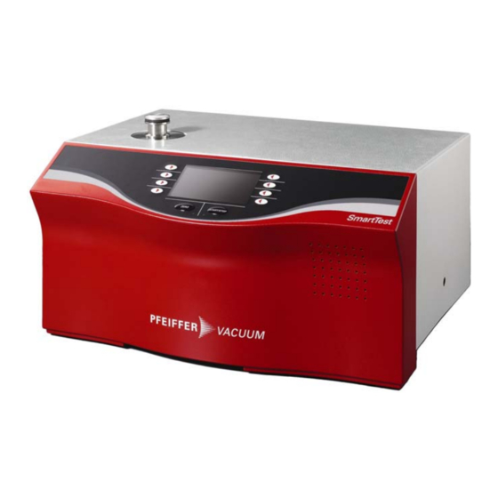
- Page 1 SmartTest HLT 550 HLT 560 HLT 570 Operating Instructions...
- Page 2 Product identification The data specified on the rating plate are necessary in correspondence with Pfeiffer Vacuum. Therefore transfer the data to the copy. Fig. 0-1 Validity This document is valid for products with the article number SmartTest PT L02 100 (HLT 560, 230 V~, with rotary vane pump UNO 005 A) PT L02 101 (HLT 560, 120 V~, with rotary vane pump UNO 005 A)
-
Page 3: Table Of Contents
Content Safety Directions for Use 1.1.1 Use of this Manual 1.1.2 Symbols Used General Safety Precautions 1.2.1 Use for the Intended Purpose 1.2.2 Responsibility and Guarantee 1.2.3 Personnel 1.2.4 General Safety Rules Scope of Delivery Technical Data General Mains Connection Environmental Data Measure Interfaces... - Page 4 6.2.4 Calibration 6.2.5 Measuring mode Vacuum / Sniffing Measure 6.3.1 Measure with a test item 6.3.1.1 Vacuum mode 6.3.1.2 Sniffing mode 6.3.2 Measured Value Display 6.3.3 Display Range Settings 6.3.4 Volume Setup 6.4.1 View 6.4.1.1 Contrast 6.4.1.2 Units 6.4.1.3 Time & Date 6.4.1.4 Display Range 6.4.1.5...
- Page 5 6.4.7.4 Maintenance List 6.4.7.5 Service Calibration Vacuum Method Calibration Sniffing Method Measuring the Internal Test Leak Errors Malfunction Messages Warnings Changing Mains Fuses Disposal Accessories and Consumer Materials Appendix Remote Control RC 500 WL Interfaces List of Default Values Pirani-Characteristic List of literature Declaration of Contamination Declaration of Conformity...
-
Page 7: Safety
Safety Directions for Use 1.1.1 Use of this Manual This chapter describes the safety requirements which must be observed on all accounts when using the SmartTest Helium Leak Detector. All persons working on and with the leak detector must have read and understood the chapters relevant to their activities. -
Page 8: General Safety Precautions
General Safety Precautions 1.2.1 Use for the Intended Purpose The SmartTest Helium Leak Detectors serve for measurement and localization of small and very small leaks both on components and modules and on fittings and systems. They are suitable both for underpressure leak testing (vacuum method with or without partial current operation) and for overpressure leak testing (sniffing method). - Page 9 Warning The Helium Leak Detector SmartTest may not be operated in standing or under flowing or dripping water. The same applies for all other kinds of liquids. Avoid contact of the SmartTest with bases, acids and solvents as well as extreme climatic conditions.
-
Page 10: Responsibility And Guarantee
Note Caution: Danger of injury Although this instrument is distinguished by high standards of quality and safety and has been built and tested according to the latest state of the art, injury or material damages cannot be totally ruled out in the event of misuse or use for a purpose which was not intended. -
Page 11: General Safety Rules
Maintenance personnel The maintenance personnel may operate the SmartTest leak detector in normal operation and perform maintenance work necessary for trouble-free operation of the instrument. In order to be authorised to maintain the SmartTest leak detector, the person concerned must have taken part in an initial training conducted by a Pfeiffer Vacuum employee or an experienced member of staff of the system user. - Page 12 Danger S TOP Caution: Mains voltage Improperly earthed products may be dangerous to life in the event of a malfunction. Connect the product in accordance with local regulations and earth correctly. Interruption of the earthed conductor inside or outside the instrument is not permissible.
- Page 13 A completed and signed "Contamination Declaration" (see: www.pfeiffer-vacuum.net and appendix Declaration of Contamination) must be enclosed with every product sent in for repair. Spare parts Only original spare parts may be used for repairs. See maintenance Instructions IG 0108 BEN.
-
Page 14: Scope Of Delivery
Scope of Delivery The scope of delivery includes the following parts: • Basic device HLT 5xx • Power-Subcon; relay plug • Cap for Power-Subcon; relay plug • Connecting plug: Ventilation sniffer connection • Filter mat fan 500 μm • Power cable •... -
Page 15: Technical Data
Technical Data General Dimensions 550×460×304 mm (L×W×H) Weight 44 kg HLT 560, HLT 570 34 kg HLT 550 approx. 150 kg HLT 565/572/575 with carriage and pump Max. permissible acceleration 1 G (horizontal) in operation Test connection DN 25 ISO-KF Cooling air Inlet Bottom, with dust filter... -
Page 16: Measure
Storage –10 °C … +55 °C +10 °C … +35 °C Operation Relative humidity max. 80% up to +31 °C, decreasing to 50% at +35 °C Only indoors, altitude up to 2000 m above sea level Noise level <70 dB/A (according to IEC standard) Measure Operating modi Vacuum / sniffing... -
Page 17: Interfaces
at volume 0.5 l 2 s (HLT 560, HLT 570) 70 s (HLT 560) at volume 10 l 200 s (HLT 570) 700 s (HLT 560) at volume 100 l 2100 s (HLT 570) Pump time up to first measurement at volume 0.5 l 2 s (HLT 560, HLT 570) 45 s (HLT 560) -
Page 18: Turbo Pump
HLT570 Pfeiffer Vacuum MVP 035 Two-stage diaphragm pump, oil-free Volume flow rate 2 m³/h Turbo Pump Pfeiffer Vacuum SplitFlow 80 Turbo pump with interstage pumping Volume flow rate for N 60 l/s... -
Page 19: Description
Description The SmartTest Helium Leak Detectors are microprocessor-controller leak detecting instruments. All the processes in the instrument are controlled automatically. Fig. 3-1 Test connection KF25 connection for connecting test objects Rear Rear with mains connection, interfaces, connection for remote control, sniffing probe and venting Instrument operation Display and control unit... -
Page 20: Measuring System
Measuring System The measuring system consists (simplified) of: • a test connection • a backing pump • a turbo pump • a few valves • a helium sensor test rest connection helium sensor turbo pump test leak part A part B Gas connection for sniffing probe or venting line... -
Page 21: Detection Principles
Detection Principles Counterflow The sample is connected to the backing pump via valve V2. At a pressure p2 £ 15 mbar *) the valve V1 to the turbo pump is opened. Helium can get to the helium sensor through the two partial pumps A and B against the pumping direction. -
Page 22: Leak Detection Methods
Leak Detection Methods When searching for leaks with the SmartTest the test gas entering or escaping through leaks in the sample is detected. For gas to flow through a leak a pressure difference between the inside and outside of the sample is necessary. For this either excess pressure or vacuum pressure is generated inside the sample. - Page 23 Sniffing method In the sniffing method the test gas escaping from leaks in the sample into the atmosphere is detected. The sample must withstand the applied test pressure. In operation with the sniffing probe a constant gas flow is sucked in from the atmosphere.
-
Page 24: Test Gases
Test Gases For reasons of economy and detection sensitivity He (helium with mass 4) is generally used as a test gas for leak detection. Under certain conditions, e.g. at increased He concentration on the sample, it may be useful to change to a different test gas such as He (helium with mass 3) or H (hydrogen, mass 2). -
Page 25: Background Suppression
Background Suppression The background signal may increase dependent on the measuring conditions (e.g. high percentage of helium in the ambient air). The background signal can be suppressed to enable easy measurement of small leak rates despite a high background. The background suppression can be locked or activated automatically with every START. - Page 26 Falling background Fig. 3-4 Falling background Item Description raw signal saved value displayed leak rate If the raw signal falls below the saved background value this is automatically set equal to the raw signal (e.g. at time t1). As soon as the raw signal rises again (e.g. at time t2), the saved background value remains constant.
- Page 27 Fig. 3-5 Absolute measurement Zero constant function Fig. 3-6 Zero constant function Item Description raw signal saved value displayed leak rate By pressing the ”ZERO” key the momentary raw signal (e.g. at time t1, t2, t5) is saved as a background value and is then subtracted from the following measured values/raw signals.
- Page 28 The automatic background suppression is locked. The zero value is retained after pressing the Stop key. Pressing the Zero key again overwrites the zero value. The zero value is set to ”0” at Power Off or changing the zero function. If the raw signal of the leak rate drops below the saved value/background value (see time: t3 to t4), it is not evaluated but the slightest detectable leak rate/detection limit is displayed.
-
Page 29: Manual Control Elements
Manual Control Elements Instrument Operation The operating unit is the display, operation and control unit for the leak detector. Fig. 4-1 Functions of the buttons on the display START/STOP key The measuring process is started and stopped with the START/STOP key. ZERO key ZERO activates the background suppression in measurement mode. -
Page 30: Commissioning
Commissioning Installation, Assembly Note See the Chapter ”Technical Data” (Chapter 2) regarding the permissible ambient temperature, degree of protection, voltages, max. acceleration of the instrument in operation etc. Despite good attenuation and vibration decoupling of the mechanical pumps in the SmartTest, vibrations of the instruments can never be ruled out totally. -
Page 31: Transport Lock
Allan head screws (size 4) at the label. Keep the screws. The screws must be reinserted for transport. Mount the External Backing Pump SmartTest HLT 550 The external backing pump is connected at the bottom via the connection flange DN 25 ISO-KF. Other SmartTest models If large volume objects need to be tested, an additional backing pump can be connected at the bottom via the additional connection flange DN 25 ISO-KF. -
Page 32: Mounting Accessories
Mounting Accessories 5.3.1 Sniffing Probe Connect the sniffing probe as illustrated for sniffing operation. Fig. 5-2 Connections for sniffing probe Input / output connection RC connection Electrical connection for sniffing probe Gas connection for sniffing probe or venting line (hose nipple ø 6/4 mm) Exhaust gas connection (¼"... -
Page 33: Bypass Option
5.3.3 Bypass Option Connect the 25 poles D-sub connector of the bypass option to connection 1 (Input / Output). See also Operating Instructions. 5.3.4 Signal tower Connect the 25 poles D-sub connector of the signal tower to connection 1 (Input / Output). - Page 34 Note Connection data Before connecting, make sure that the operating voltage of the instrument matches the local mains voltage. You will find the specifications on the rating plate on the back of the instrument.
-
Page 35: Operation
Operation Switching On and Off Check the correct installation of all cables and accessories and compliance with the ”Technical Data”. The mains switch is on the back of the housing. Switch on the instrument. The instrument can be switched off at any time and in any state. The current settings will be saved. - Page 36 The instrument designation is displayed after switching on – the instrument runs a self-test. Fig. 6-2 Display SmartTest After the self-test, the message "Pfeiffer-Vacuum; SmartTest" is displayed. Note For the most accurate measurements or for calibration, the SmartTest should be allowed to warm up for at least 30 minutes The run-up of the turbo pump starts.
- Page 37 Run-up Details With the ”Details” softkey you go to the Run-up Details menu with • the current fore-vacuum pressure • the speed of the turbo pump • the current consumption of the turbo pump • the status of emission • the active filament Fig.
- Page 38 Fig. 6-6 Venting TMP 2 After that the TMP will be vented for 10 seconds. TMP vented Fig. 6-7 Venting TMP 3 When this 10 seconds have passed the leak detector has to be switched off. The maintenance of the lubricant can be started now. You can start the leak detector again with the softkey "start new".
-
Page 39: Ready To Start
Ready to start Fig. 6-8 Ready to start The instrument now displays the following parameters: Mode Operating mode (vacuum or sniffing) Mass Type of gas (He4, He3, H2) Filter Filter stage (without, dynamic, normal) Date and calibration factor of the last calibration of Twin- Flow high (Twin-Flow low for sniffing). -
Page 40: Regeneration
6.2.1 Regeneration Select Setup Regeneration The "Regeneration" is an automated Start-Stop - cycle intended for the reduction of a raised helium background. This function can only be successful activated in the setting "Venting: with Stop". You can deactivate the "Regeneration" in general with the STOP key or with STOP in the "Regeneration"... -
Page 41: Calibration
6.2.4 Calibration This function is only shown if the calibration is enabled in the Access Control mode (see Chapter 6.4.2.3). Select Ready to Start Calibration This option commences the calibration routine. See chapter or 6.6, respectively. 6.2.5 Measuring mode Vacuum / Sniffing This function is only shown if the software menu is not locked by menu PIN (see Chapter 6.4.2.1) Select... - Page 42 Option Value range Description (Min. / Max.) Mode Vacuum Vacuum mode Sniffing Sniffing mode1) Mass H2 (2 amu) detectable gas H2 3H (3 amu) detectable gas 3H 4He (4 amu) detectable gas 4He Leak rate factor Factor Leak rate is converted with user- 1E-6 …...
-
Page 43: Measure
Measure 6.3.1 Measure with a test item The instrument is ready to detect leaks as soon as it displays Ready to start: • Select the desired measuring mode Mode: Vacuum or Sniffing • Check whether the parameters displayed in the Start menu are applicable. 6.3.1.1 Vacuum mode Danger S TOP... -
Page 44: Measured Value Display
Fig. 6-11 Pump fore-vacuum The pressure during the pump down process is displayed. 6.3.2 Measured Value Display On reaching the measuring pressure, the measured value display appears with the display type last used: • analog/digital with bar display and large numbers or •... -
Page 45: Display Range Settings
Graphic display Fig. 6-13 Graphic display (manual scaling) You can restart the graph with the softkey New. With the softkey Print the leak rate, date and time are send to a printer that is connected with the serial port. The interface protocol „Printer“ must be selected (see 6.4.4.4.5). -
Page 46: Setup
Setup You can go to the Setup menu by pressing the ”Setup” softkey in any menu which displays it. Note Observe the detailed instructions for handling the keys in this and the following two chapters. Thereafter only menus, parameters and value tables are described. -
Page 47: Contrast
6.4.1.1 Contrast Select Setup View Contrast Fig. 6-16 View of the ”Contrast” setting in the display • Select the desired option with the softkeys on the right and left of the screen. • Change its value with the ”+” and ”-”keys, prolonged pressing causes the parameters to be run through automatically. -
Page 48: Units
6.4.1.2 Units Select Setup View Units Fig. 6-17 View of the ”Units” setting in the display Option Value range Description (Min. / Max.) Leak rate mbar *l/s Pa*m3/s Torr*l/s sccm sccs atm*cc/s (only selectable in ”Sniffing” mode) (only selectable in ”Sniffing” mode) oz/yr (only selectable in ”Sniffing”... -
Page 49: Time & Date
6.4.1.3 Time & Date Select Setup View Time & Date Fig. 6-18 View of the ”Time & Date” setting in the display Option Value range Description (Min. / Max.) Date e.g. 25th Jan. 2011 Date: Days 1 - 31 Month: Jan. - Dec. Year: 1998 - 2097 Time e.g. -
Page 50: Lower Display Limit
Option Value range Description (Min. / Max.) Scaling linear Display linear Display logarithmic 2 … 9 Number of decades in log. display dec. Range automatic automatic range selection manual manual range selection Time axis 16 … 960 Time axis, time scale in seconds 6.4.1.5 Lower Display Limit Select... -
Page 51: Background At "Ready To Start
6.4.1.6 Background at “Ready to Start” Select Background at “Ready to Start” Setup View Fig. 6-21 View of the ”Ready to start” setting in the display 6.4.2 Access Control Select Setup Access Control Fig. 6-22 View of the ”Access Control” setting in the display... -
Page 52: Change Menu-Pin
6.4.2.1 Change Menu-PIN Select Setup Access Control Change Menu PIN Confines / allows to access the software menu. Exception: The menu Information is always available (See Chapter 6.4.6). Access to the menu can be restricted by entering or changing the personal identification number (PIN). -
Page 53: Change Device Pin
6.4.2.2 Change Device PIN Select Setup Access Control Change Device PIN Confines / allows to use the leak detector. Access to the leak detector can be restricted by entering or changing the personal identification number (PIN). If the instrument PIN is not 0000, the leak detector asks for the PIN immediately after being switched on. -
Page 54: Calibration Enabled
6.4.2.3 Calibration Enabled Select Setup Access Control Calibration Enabled Authorizes for calibration of the leak detector. Fig. 6-25 View of the ”Enable calibration” setting in the display Option Value range Description (Min. / Max.) Enable calibration The calibration can be started from the ”Ready to start”... -
Page 55: Maintenance Enabled
6.4.2.4 Maintenance enabled Select Setup Access Control maintenance enabled Enables the user to use the maintenance menu and the venting of the TMP for changing the lubricant. Fig. 6-26 Maintenance enabled Maintenance The menu page Maintenance & Service is enabled. When enabled running-up the TMP can be vented. -
Page 56: Language
6.4.3 Language Select Setup Language Fig. 6-27 View of the ”Language” setting in the display Option Value range Description (Min. / Max.) Language English Operating language English German Operating language German French Operating language French Spanish Operating language Spanish Chinese Operating language Chinese Russian Operating language Russian... -
Page 57: Mode & Mass
6.4.4.1 Mode & Mass Select Setup User settings Mode & Mass Fig. 6-29 View of the ”Mode & mass“ setting in the display Option Value range Description (Min. / Max.) Mode Vacuum Vacuum mode Sniffing Sniffing mode1) Mass H2 (2 amu) detectable gas H2 3H (3 amu) detectable gas 3H... - Page 58 Example We measure the test gas helium 4 and want to display the leak rate for air: Mass He × × × LR Air LR He ---------------------------- LR He ----------------------- - LR He 0.372 Mass Air 28.964 With leak rate factor air the leak rate is converted according to the equation with the mass of the test gas (4, 3 or 2) to an equivalent leak rate for air under molecular conditions.
-
Page 59: Filter & Zero
6.4.4.2 Filter & Zero Select Setup User settings Filter & Zero Fig. 6-30 View of the ”Filter & Zero” setting in the display Option Value range Description with variable time constant (Min. / Max.) Filter dynamic Leak rate filter with dynamic adaptation of the time constant static Leak rate filter with fixed time constant... - Page 60 MS-BG The internal mass spectrometer background is subtraction subtracted at START. The internal background is generated by residual available in gas (e. g. Helium) that has not been pumped away option yet. Sources for residual gas are air or absorbed “Zero gases from the inner surfaces of the leak detector.
-
Page 61: Alarm
6.4.4.3 Alarm Select Setup User Settings Alarm Fig. 6-31 Warning The hearing can be harmed by the audio alarm. The acoustic output can exceed a level of 85dB(A). Do only expose to the audio alarm for a short time or use ear protection. Option Value range Description with variable time constant... -
Page 62: Interfaces
Option Value range Description with variable time constant (Min. / Max.) Mode Pinpoint The frequency of the acoustic signal is proportional to the leak rate between 0.1*setpoint value and 10*setpoint value. A constant low tone is emitted if the leak rate is lower than 0.1*setpoint value. -
Page 63: Analog Output
6.4.4.4.1 Analog Output Select Setup User Settings Interfaces Analog Output Fig. 6-33 Option Value range Description with variable time constant (Min. / Max.) Channel 1 Channel 1 is switched off (0 V) Pressure p2 The inlet pressure p2 is output on channel 1. (See pirani characteristic in appendix) Pressure p1 The fore-vacuum pressure p1 is output on channel... - Page 64 Option Value range Description with variable time constant (Min. / Max.) Channel 1 LR log. The output voltages are scaled logarithmically. The output voltage is 0…10 V in adjustable steps of 0.5 V to 10 V per decade (see Scaling setting). The upper limit (=10V) is forced through the adjustment “scaling →...
-
Page 65: Compact Gauge
6.4.4.4.2 Compact Gauge Setup User Settings Interfaces Compact Gauge Fig. 6-34 Compact Gauge Option Value range Description with variable time constant (Min. / Max.) Full 0.1 mbar Set the full deflection value (F.S.) according to the deflection 1 mbar rating plate of the gauge head. (only in 10 mbar linear gauge... -
Page 66: Control Location
6.4.4.4.3 Control Location Select Setup User Settings Interfaces Control Location Fig. 6-35 View of the ”Control location” setting in the display Option Value range Description (Min. / Max.) Control location Local The HLT5xx is controlled by the START, STOP and ZERO keys. Local and The HLT5xx is controlled both by RS232 / RS485... -
Page 67: Relay
6.4.4.4.4 Relay Setup User Settings Interfaces Relay Fig. 6-36 Relay view of the ”Relay” setting in the display Relay allows independent settings for the two output relays. Parameter Settings Explanation Relay 1 Off 1) Relay always dropped out Start Relay activates when valve V2 opens and drops when valve V2 closes Relay 2 (→... -
Page 68: Serial Port
6.4.4.4.5 Serial Port Select Setup User Settings Interfaces Serial Port Fig. 6-37 Serial port Option Value range Description (Min. / Max.) Interface RS232 / RS485 Selection whether the RS232 or the RS485 is to be used. HLT2xx The interface protocol of the HLT2xx. -
Page 69: Bypass Option
6.4.4.4.6 Bypass Option This option is only available, if a bypass valve is installed. Select Setup User Settings Interfaces Bypass Option Fig. 6-38 View of the ”Bypass option” setting in the display Option Value range Description (Min. / Max.) Mode No bypass see below Partial flow... -
Page 70: Parameter Save / Load
6.4.4.5 Parameter save / load Select Setup User settings Parameter save / load Fig. 6-39 Parameter save / load 6.4.4.5.1 Load PARA Set 1 / 2 Select Setup User settings Parameter save / load Load PARA Set 1 / 2 Fig. -
Page 71: Load Factory Settings
6.4.4.5.2 Load Factory Settings Select Setup User Settings Parameter save / load Load Factory Settings Fig. 6-41 Default parameter List of default parameter see appendix. 6.4.4.5.3 Save PARA Set 1 / 2 Select Setup User settings Parameter save / load Save PARA Set 1 / 2 Fig. -
Page 72: Monitoring Functions
6.4.4.6 Monitoring functions Select Setup User Settings Monitoring Functions Fig. 6-43 Monitoring functions 6.4.4.6.1 Flow Select Setup User Settings Monitoring Functions Flow Fig. 6-44 Flow menu Option Value range Explanation (Min. / Max.) Flow min. 1…40 sccm The warning ”Flow too low” appears if the flow drops below this value during the measuring mode. -
Page 73: Contamination Protection
6.4.4.6.2 Contamination Protection Select Setup User Settings Monitoring Functions Contamination Protection Fig. 6-45 View of the ”Contamination protection” setting in the display Option Value range Explanation (Min. / Max.) Protection Contamination protection is switched on Contamination protection is switched off Limit 1E-9 …1E+3 Switch off limit value for the... -
Page 74: Volume & Beep
6.4.4.6.3 Volume & Beep Select Setup User Settings Monitoring Functions Volume & Beep Fig. 6-46 Volume settings Option Value range Explanation (Min. / Max.) Minimum volume 0…15 The minimum volume must be reached. This prevents the volume being accidentally set so quiet that you can no longer hear the alarm signal. -
Page 75: Valves
6.4.4.6.4 Valves Select Setup User Settings Monitoring Functions Valves Fig. 6-47 View of the ”Valves” setting in the display Option Value range Explanation (Min. / Max.) Twin-Flow high released released locked locked 0.01 … 0.5 mbar Pressure at which valve V4 opens Twin-Flow low released released... -
Page 76: Evacuation Time & Vent
6.4.4.6.5 Evacuation Time & Vent Select Setup User Settings Monitoring Functions Evacuation Time & Vent Fig. 6-48 View of the ”Evacuation time & Venting” setting in the display Option Value range Explanation (Min. / Max.) Maximum 1s … 30 min If the sample has a strong leak it evacuation time infinitely... - Page 77 Regeneration Select Setup User Settings Monitoring Functions Evacuation Time & Vent Regeneration The “Regeneration” is an automated Start-Stop - cycle intended for the reduction of a raised helium background. This function can only be successful activated in the setting “Venting: with STOP”. You can deactivate the “Regeneration”...
-
Page 78: Calibration Request
6.4.4.6.6 Calibration Request Select Setup User Settings Monitoring Functions Calibration Request Fig. 6-50 View of the ”Calibration request” setting in the display • Select the desired option with the softkeys on the right and left of the screen. • Save the new value with ”Save” or •... -
Page 79: Calibration Settings
6.4.5 Calibration Settings Select Setup Calibration Settings In this parameter group settings for the calibration but not the calibration itself are made. Fig. 6-51 Calibration settings Option Value range Description (Min. / Max.) Unit e.g. mbar*l/s The unit for the test leak value. For internal test leak fixed at mbar*l/s. -
Page 80: Information
6.4.6 Information Select Setup Information Fig. 6-52 Information menu 6.4.6.1 Settings Select Setup Info Settings Fig. 6-53 Settings menu... -
Page 81: System Data
6.4.6.2 System Data Select Setup Info System Data Fig. 6-54 System data (page 1/4 pump data) 6.4.6.3 Vacuum System Select Setup Info Vacuum System Fig. 6-55 Vacuum system... -
Page 82: Error List
6.4.6.4 Error List Select Setup Info Error List Fig. 6-56 Error list 6.4.6.5 Calibration History Select Setup Info Calibration History Fig. 6-57 Calibration history... -
Page 83: Paging Function Remote Control Rc 500 Wl
6.4.6.6 Paging function remote control RC 500 WL Select Setup Info Paging function Fig. 6-58 Paging function A wireless remote control RC 500 WL must be installed and be switched on. With the paging function the remote control RC 500 WL lets itself locate and assign acoustically from the leak detector. -
Page 84: Maintenance And Service
6.4.7 Maintenance and Service Select Setup Maintenance & Service The maintenance menu can only be chosen when the maintenance was enabled under "setup - access control - maintenance enabled". Fig. 6-59 Maintenance and service 6.4.7.1 Maintenance device Select Setup Maintenance & Service Maintenance device Fig. -
Page 85: Burn In
6.4.7.2 Burn In Select Setup Maintenance & Service Burn-In The “Burn-in” is an automated Start-Stop - cycle. This function can only be successful activated in the setting “Venting: with Stop”. See Chapter 6.4.4.6.5. An active “Burn-in” will be announced in the display. You can deactivate the “Burn- in”... -
Page 86: Maintenance Interval Components
6.4.7.3 Maintenance Interval Components Select Setup Maintenance & Service Maintenance Components Fig. 6-62 Maintenance components Under "maintenance components" the current operating hours of the components fore pump, turbo pump and ion source are shown since the last maintenance was accomplished. After each maintenance the counter can be reset. This leads to a new entry in the list of maintenance intervals. -
Page 87: Service
6.4.7.5 Service Select Setup Maintenance & Service Service Fig. 6-64 Access with service PIN The access to the menu ”Service” is only possible with a Service-PIN. Please enter the Service-PIN. -
Page 88: Calibration Vacuum Method
Calibration Vacuum Method Note The instrument must have warmed up for at least 20 minutes for optimum calibration. Please observe the recommended test interval of the used test leak! See quality test certificate: Test leak In the vacuum mode the calibration of the SmartTest can be carried out with an internal or external test leak. - Page 89 Note test leak Partial flow arrangement: When connecting the SmartTest to a vacuum system with its own pump, the test leak must test be connected to its test vessel. vessel SmartTest Fig. 6-67 Calibration run The calibration runs through the following sequence: Fig.
- Page 90 Fig. 6-71 Fig. 6-72 Fig. 6-73 In calibration with an external test leak the prompt appears: Fig. 6-74 • Close test leak valve Fig. 6-75 Fig. 6-76 • Wait 5 minutes with test gas H • Confirm with OK...
- Page 91 In calibration with an external or internal test leak in the ”Manual internal” mode, the stability of the signal must be confirmed with the ”ok” softkey. Fig. 6-77 Fig. 6-78 The result is displayed at the end of the calibration process. Fig.
-
Page 92: Calibration Sniffing Method
Calibration Sniffing Method Note The instrument must have warmed up for at least 30 minutes for optimum calibration. Please observe the recommended test interval of the used test leak! See quality test certificate: Test leak Press ”Calibration” in the Ready to start menu to start calibration. The prompt appears: Fig. - Page 93 Calibration run The calibration runs through the following sequences: Fig. 6-82 Fig. 6-83 The stability of the signal must be confirmed with the ”OK” softkey. Fig. 6-84 Fig. 6-85 The prompt now appears: Fig. 6-86 • Remove the sniffing probe from the test leak. •...
- Page 94 Fig. 6-87 The result is displayed at the end of the calibration process. Fig. 6-88 The usual value calibration factor CF for He is: 0.1 … 10. If you: accept the result, press ”Save ” to save the new calibration values •...
-
Page 95: Measuring The Internal Test Leak
Measuring the Internal Test Leak This function is only available in the vacuum mode with mass 4. After running up the instrument the display changes to Ready to start! Fig. 6-89 Ready to start Softkey ”Test internal leak” leads to sub-menu: Fig. - Page 96 Fig. 6-92 The display also shows the default value of the internal test leak in addition to the measured test leak value: e.g.: TL: 8.3E-07 mbarl/s. Softkey ”Escape” always returns you to the menu: Ready to start Note Matching of the measured value of the internal test leak and the default value of the internal test leak does not mean that the measuring system is absolutely accurate if the internal test leak was used for calibrating the leak detector.
-
Page 97: Errors
Errors Errors are displayed by warnings and malfunction messages. Warnings point at a problem but you usually still can measure during that time. Measuring is no longer possible when malfunction messages are displayed. Warnings and malfunction messages are signalized by an audible alarm. It’s frequency is changing between 500Hz and 1200Hz every 400ms. - Page 98 Malfunction messages Displayed message Description and possible remedy of cause Display Pfeiffer Protocol E126 Anode-cathode voltage Anode-cathode voltage is greater than U > 130 V. is too high! • MSV is defective. E127 Anode-cathode voltage Anode-cathode voltage is less than U < 30 V. is too low! •...
- Page 99 Malfunction messages Displayed message Description and possible remedy of cause Display Pfeiffer Protocol E 43 E 149 Emission Off (p2 too The emission is switched off during normal operation of the high) leak detector when: • in CF P2 > (pressure limit CF + 5 mbar) or •...
- Page 100 Malfunction messages Displayed message Description and possible remedy of cause Display Pfeiffer Protocol E006 TMP acceleration time Speed of the SplitFlow 80 is 15 min. after starting below the too high (E006)! speed switching point < 1200 Hz. • Turbo pump bearing damage •...
-
Page 101: Warnings
Warnings Warnings no. Displayed message Description and possible remedy of cause Display Pfeiffer Protocol E167 TMP-Fault • Unknown error code W101 W064 Real time clock reset! Real-time clock reset. Please re-enter the date and time. Please enter date and • Battery on MC 68 control circuit board discharged or time! defective... - Page 102 Warnings no. Displayed message Description and possible remedy of cause Display Pfeiffer Protocol W106 W067 Default Settings loaded! The factory settings have been loaded by the instrument software. W107 W090 Service interval • Perform service backing pump expired! • Perform service SplitFlow 80. After the confirmation of this warning a “warning triangle”...
- Page 103 Warnings no. Displayed message Description and possible remedy of cause Display Pfeiffer Protocol W126 W074 Calibration factor too The calculated calibration factor is outside the permissible high! range (> 100). The old factor is retained. • The test leak is defective or empty. •...
- Page 104 Warnings no. Displayed message Description and possible remedy of cause Display Pfeiffer Protocol W135 W077 Emission for filament 1 • Filament 1 defective can not be switched on! • Defective ion source connector or cable. • MSV card defective. • Filament 2 defective W136 W078...
-
Page 105: Changing Mains Fuses
Warnings no. Displayed message Description and possible remedy of cause Display Pfeiffer Protocol W160 W086 Leak rate too high! The monitor function ”Contamination protection” is activated Switched to Stand-By to and a leak rate above the set limit value has been detected. prevent contamination! •... - Page 106 Lever open and lift the cover of the fuse holder. Fig. 7-93 Change the mains fuses (1) Remove both fuse holders and replace defective fuses (10.0 A slow blow, 250 V, Ø5 x 20 mm). Fig. 7-94 Snap the fuse holder back together. Close the cover.
-
Page 107: Disposal
Disposal Danger S TOP Caution: Contaminated parts Contaminated parts can cause damage to health and the environment. Find out about possible contamination before starting work. Observe the pertinent regulations and safety precautions when handling contaminated parts. Warning Caution: Materials which are harmful to the environment Products or parts (mechanical and electrical components, operating fluids etc.) can be harmful to the environment. -
Page 108: Accessories And Consumer Materials
Accessories and Consumer Materials Basic instrument Order number Filter mats (5 pieces) B 8199 999 EG Carriage for SmartTest, prepared for fore pump 230 V∼, 50 Hz PT 445 415 100 … 120 V∼, 50 … 60 Hz PT 445 416 Transport case for SmartTest PT 445403 Scratch guard for SmartTest... - Page 109 Bypass-option Order number With main cable and German plug PT 445 410 -T With main cable, VL PT 445 412 -T Signal tower Order number Signal tower (lamp) green / red for optical leak indication B 4681 891 KC External test leaks Order number Calibrated helium vacuum test leak CT 406 1…3x10⁻⁶ mbar l/s...
-
Page 110: Appendix
Appendix Remote Control RC 500 WL Like the instrument operating unit the remote control RC 500 WL is a display operation and control element, measured values of up to 24 hours of recording can be stored in an internal memory. It offers the advantage of simple wireless operation of the leak detector from a distance of up to 100 m and is also connectable by a cable with the leak detector. -
Page 111: B Interfaces
LED operation Signals by flashing the operation of the Remote Control. LED Charge Lights up while the battery is being charged. The Remote Control is an optional accessory and is therefore not included in the standard delivery scope. It can be ordered separately if required with the appropriate accessories (see Chapter 9). - Page 112 GAUGE HEAD Signal Identification DGND (0 V) Measuring signal Measuring signal Screening +24 V (fuse 0.8 A slow blow) Fig. 10-3 Usable compact gauge heads Linear gauge heads Display Gauge head designation Operating unit Compact Capacitance Gauges linear CMR 261, CMR 262, CMR 263, CMR 264, CMR 271, CMR 272, CMR 273, CMR 274...
- Page 113 Signal Explanation Analog output 0 … 10 V, Ri 3 Ω, function. See CHANNEL 1 6.4.4.4.1 CHANNEL 2 Analog output, data as above. See 6.4.4.4.1 AGND Reference potential analog outputs, galvanically isolated Audio output (headphones or active speaker) Reference potential to audio output 6 …...
- Page 114 Example of digital inputs: Fig. 10-5 Example of digital inputs When accessing via +24V of the leak detector a connection between PIN14 and PIN23 has to exist. Remote control The remote control interface is designed as a serial interface for controlling the SmartTest by remote control, if the wired version is used.
- Page 115 RS485 The connection of the SmartTest to a computer can be made through the serial interface RS485. free +24 V (for supplying the field bus converter; fuse 0.8 A slow blow) free free D+ (galvanically isolated) DGND (0 V) D- galvanically isolated) free Fig.
- Page 116 RS232 Connection for computer 9-pole, D-Sub sockets, RS232 (option RS485) Signal Transmit data (galvanically isolated) Receive data (galvanically isolated) GGND Reference potential (galvanically isolated) Fig. 10-7 RS232 interface See RS232 Fig. 10-2/3. Relay 1, Relay 2 Relay contact 230 V~, 3 A Plug SmartTest Power Subcon, 3-pole Fig.
-
Page 117: C List Of Default Values
List of Default Values Parameter Default Values Setting back Included in to VORGABE- set of WERT when parameters loading default values contrast invert display leak rate unit mbar l/s pressure unit mbar scaling decades at scaling log. display unit automatic time axis 32 Seconds lower display limit... - Page 118 Parameter Default Values Setting back Included in to VORGABE- set of WERT when parameters loading default values full scale (lin. gauge head) 1000 mbar setpoint value for ext. gauge heads 1E-1 mbar pressure P2 source internal control location local, RS232/RS485 mode relay 1 mode relay 2 interface...
-
Page 119: D Pirani-Characteristic
Pirani-Characteristic Fig. 10-10... -
Page 120: E List Of Literature
List of literature Operating manual Sniffer Probe LP 503, LP 505, LP 510 BG 805 268 BEN Operating manual Bypass-Option PL0002 BN Operating manual Cart for SmartTest IG 0110 BEN Communication Protocol SmartTest IG 0105 BEN Maintenance Instructions SmartTest IG 0108 BEN Operating instructions RC 500 WL / RC 500 IG 0140 BEN Declaration of Contamination... -
Page 121: G Declaration Of Conformity
Declaration of Conformity Declaration of Conformity SmartTest Product Helium Leak Detector HLT 550 HLT 560 HLT 570 Art.-No. PT L02 100 PT L02 110 PT L02 120 PT L02 101 PT L02 111 PT L02 102 PT L02 112 Declaration of Conformity in accordance We herewith declare that the aforementioned products confirm to the with the listed EC directives regulations in the subsequently listed guidelines. - Page 124 Leading. Dependable. Pfeiffer Vacuum stands for innovative and custom vacuum Customer Friendly. solutions worldwide. For German engineering art, competent advice and reliable services. Ever since the invention of the turbopump, we´ve been setting standards in our industry. And this claim to leadership will continue to drive us in the future.
Need help?
Do you have a question about the SmartTest HLT 550 and is the answer not in the manual?
Questions and answers