Table of Contents
Advertisement
Quick Links
Published 08/01
OPERATOR'S MANUAL
This Operator's Manual is an integral part of the safe operation
of this machine and must be maintained with the unit at all
times. READ, UNDERSTAND, and FOLLOW the Safety and
Operation Instructions contained in this manual before
operating the equipment.
FUERST
1020 S. Sangamon Ave.
Gibson City, IL 60936
217-784-4261
Serial No. FB42-10017 Through Current
© 2004 Alamo Group Inc.
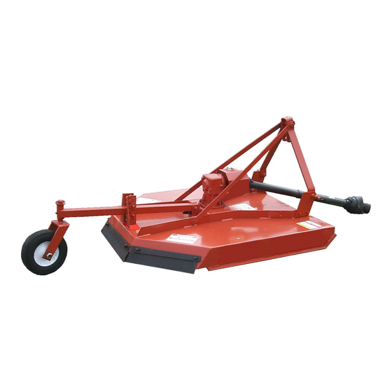
FB42
ROTARY MOWER
P/N 00768114C
$0.00
Advertisement
Chapters
Table of Contents

Summary of Contents for Fuerst FB42
-
Page 1: Rotary Mower
FB42 ROTARY MOWER Published 08/01 Serial No. FB42-10017 Through Current P/N 00768114C OPERATOR'S MANUAL This Operator's Manual is an integral part of the safe operation of this machine and must be maintained with the unit at all times. READ, UNDERSTAND, and FOLLOW the Safety and Operation Instructions contained in this manual before operating the equipment. - Page 2 TO THE OWNER/OPERATOR/DEALER All implements with moving parts are potentially hazardous. There is no substitute for a cautious, safe-minded operator who recognizes the potential hazards and follows reasonable safety practices. The manufacturer has designed this implement to be used with all its safety equipment properly attached to minimize the chance of accidents. BEFORE YOU START!! Read the safety messages on the implement and shown in your manual.
-
Page 3: Table Of Contents
TABLE OF CONTENTS SAFETY SECTION ............................1-1 Safety Information ..........................1-2 Safety Decal Location ..........................1-11 INTRODUCTION SECTION ......................... 2-1 ASSEMBLY SECTION ..........................3-1 Dealer Set-up Instructions ........................3-2 Shear Pin Driveline Installation ....................... 3-2 Shield Assembly ............................. 3-2 A-Frame Installation ..........................3-3 Tailwheel Installation .......................... -
Page 5: Safety Section
SAFETY SECTION Safety Section 1-1... - Page 6 Equipment with this Signal Word are Black and Yellow. Serious injury or possible death! Decals are Black and Orange. WARNING! Imminent death/critical injury. Decals are Red and White. DANGER! (SG-1) FB42 08/01 Safety Section 1-2 © 2004 Alamo Group Inc.
- Page 7 Never dismount a Tractor that is moving or while the engine is running. Operate the Tractor controls from the tractor seat only. (SG-9) FB42 08/01 Safety Section 1-3 © 2004 Alamo Group Inc.
- Page 8 The operator and all support personnel should wear hard hats, safety shoes, safety glasses, and proper hearing protection at all times for protection from injury including injury from items thrown by the equipment. (SG-16) FB42 08/01 Safety Section 1-4 © 2004 Alamo Group Inc.
- Page 9 Never attempt to lubricate, adjust, or remove material from the Implement while it is in motion or while tractor engine is running. Make sure the tractor engine is off before working on the Implement. (SG-20) FB42 08/01 Safety Section 1-5 © 2004 Alamo Group Inc.
- Page 10 Serious injury or death to the operator or others could result if the operator is under the influnce of drugs or alcohol. (SG-27) FB42 08/01 Safety Section 1-6 © 2004 Alamo Group Inc.
- Page 11 Such a situation is extremely hazardous and could result in serious injury or even death. Inspect the cutting area for such objects before mowing. Remove any like object from the site. Never allow the cutting blades to contact such items. (SGM-6) FB42 08/01 Safety Section 1-7 © 2004 Alamo Group Inc.
- Page 12 (This will also reduce power requiredto mow, reduce wear and tear on the Mower drivetrain, spread cut material better, eliminate streaking, and make the final cut more uniform.) (SRM-1) FB42 08/01 Safety Section 1-8 © 2004 Alamo Group Inc.
- Page 13 60 seconds after the brake has been set, the PTO disengaged, the tractor turned off, and all evidence of rotation has ceased. (3PT-10) “Wait a minute...Save a life!” FB42 08/01 Safety Section 1-9 © 2004 Alamo Group Inc.
- Page 14 Fuerst implement use matched system components for blades, hangers, rollers, and bearings. These parts are made and tested to Fuerst specifications. Non-genuine "will fit" parts do not consistently meet these specifications. The use of “will fit” parts may reduce implements performance, void warranties, and present a safety hazard.
- Page 15 Serial Number Plate 00776481 INSTRUCT Operators Manual Inside 00776031 --------------- Canister, Operators Manual 00768114C --------------- Operators Manual 10058000 --------------- Bolt 00024100 --------------- Flatwasher 02959924 --------------- Locknut * Furnished by the Tractor Manufacturer FB42 08/01 Safety Section 1-11 © 2004 Alamo Group Inc.
- Page 16 6 - 00756494 5 - 00756005 4 - 00756004 9 - 3438305 15 -IJ1835 FB42 3 - 00749117 - Not Shown (See Inside Front Cover of Manual) 13 - 00768111 FB42 08/01 Safety Section 1-12 © 2004 Alamo Group Inc.
- Page 17 DECALS 1 - 00725746 2 - 00773723 17 - 00776481 FB42 08/01 Safety Section 1-13 © 2004 Alamo Group Inc.
-
Page 18: Federal Laws And Regulations
Some regulations specify that no one under the age of 16 may operate power machinery. It is your responsibility to know what these regulations are in your own area or situation. (Refer to U.S. Dept. of Labor, Employment Standard Administration, Wage & Home Division, Child Labor Bulletin #102.) FB42 08/01 Safety Section 1-14 © 2004 Alamo Group Inc. -
Page 19: Introduction Section
INTRODUCTION SECTION Introduction Section 2-1... - Page 20 Mower with this Signal Word are Black and Yellow. WARNING Serious injury or possible death! Decals are Black and Orange. Imminent death/critical injury. Decals are Red and White. DANGER Introduction Section 2-2 FB42 08/01 © 2004 Alamo Group Inc.
- Page 21 INTRODUCTION Your FUERST FB42 mower is designed for light-duty cutting such as pasture mowing, weed, and grass control. With a reasonable amount of preventive maintenance, your Mower will provide years of dependable service. DANGER For Non-Agricultural use, OSHA, ASAE, SAE, and ANSI standards require the use of Chain Guards, Deflectors, or Solid Skirts at all times.
- Page 22 3. Record the Mower Model and Serial Numbers on the Warranty page at the front of the Operator’s Manual. Keep this as part of the permanent maintenance file for the Mower. Introduction Section 2-4 FB42 08/01 © 2004 Alamo Group Inc.
-
Page 23: Assembly Section
ASSEMBLY SECTION Assembly Section 3-1... -
Page 24: Dealer Set-Up Instructions
FIGURE 2. Grade 2 Shear Bolt Attach slip clutch driveline to input shaft on gearbox with Grade 8 Bolt Figure 3. Refer to proper Torque Chart in Maintenance Section of this manual. R 09-21-99 FB42 08/01 Assembly Section 3-2 © 2004 Alamo Group Inc. -
Page 25: A-Frame Installation
7. Position tailwheel beam weldment between tailwheel adjusting brackets on mainshield weldment and secure with two 1/2" x 3" bolts (8) and locknut (9). 8. Tighten all bolts to the proper torque. 17, 18 20, 21 FIGURE 5. Tail Wheel Installation. Assembly Section 3-3 FB42 08/01 R 08-12-99 © 2004 Alamo Group Inc. -
Page 26: Hydraulic Relief Assembly
FIGURE 6. Check Chain Installation For additional safety in transport, raise mower as high as possible without having driveline hit decks and shorten check chains all possible to prevent inadvertent falling in transport. FB42 08/01 Assembly Section 3-4 © 2004 Alamo Group Inc. -
Page 27: Operation Section
OPERATION SECTION Operation Section 4-1 © 2001 Alamo Group Inc. -
Page 28: Operation Instructions
Pictures contained in this section are intended to be used as a visual aid to assist in explaining the operation of a rotary mower and are not of a FB42 cutter. Some pictures may show shields removed for purposes of clarity. - Page 29 Safety Messages. Always use good common sense to avoid hazards. (SG-2) !LEA EL PELIGRO! INSTRUCTIVO! Si no lee Ingles, pida ayuda a alguien que si lo lea para que le traduzca las medias de seguridad (SG-3) FB42 08/01 Operation Section 4-3 © 2004 Alamo Group Inc.
-
Page 30: Operator Requirements
OPERATION 1. OPERATOR REQUIREMENTS Safe operation of the FB42 rotary mower is the responsibility of a qualified operator. A qualified operator has read and understands both the mower and tractor Operator Manuals and is experienced in tractor and mower operations and all associated safety practices. -
Page 31: Tractor Requirements
The power required to operate a mower is determined by the tractor PTO horsepower. For most mowing conditions, the FB42 mower requires a tractor with at least 15 HP. Operating the mower with a tractor that does not have adequate power may damage the tractor engine. Exceeding 45 HP may cause mower damage by overpowering the unit in heavy cutting conditions. -
Page 32: (2.4) 3-Point Hitch
2.6 Power Take Off (PTO) FB42 mowers are designed to operate at a PTO speed of 540 rpm. Most tractors operate at either 540, or a combination of 540 and 1000 rpm PTO speeds. The speed of the tractor PTO can be determined by the number of splines on the PTO output shaft. -
Page 33: Getting On And Off The Tractor
PTO, and lower the mower to the ground. Shut down the tractor engine according to the operator’s manual, remove the key, and wait for all motion to completely stop. Never leave the seat until the tractor, its engine and all moving mower parts are completely stopped. FB42 08/01 Operation Section 4-7 © 2004 Alamo Group Inc. -
Page 34: Starting The Tractor
Start the Tractor only when properly seated in the Tractor seat. Starting a Tractor in gear can result in injury or death. Read the Tractor operator’s manual for proper starting instructions. (SG-13) FB42 08/01 Operation Section 4-8 © 2004 Alamo Group Inc. -
Page 35: Connecting The Mower To The Tractor
3-Point hitch the same way as the mower A-frame. Mowers with a Cat I hitch will be offset approximately 13” with the use of this accessory. See Offset Adaptor Hitch in the Assembly Section for details to equip the mower with this feature. FB42 08/01 Operation Section 4-9 © 2004 Alamo Group Inc. -
Page 36: Setting The Mower
Note: Install optional check chains when there is a problem with the hydraulic 3-Point lift maintaining a set height or when a constant preadjusted cut height is required. See Check Chains in the Assembly Section for this accessory. FB42 08/01 Operation Section 4-10 © 2004 Alamo Group Inc. -
Page 37: (6.2) Setting Deck Pitch
PTO shaft. A driveline not attached correctly to the Tractor PTO shaft could slip off and result in personal injury and damage to the cutter. FB42 08/01 Operation Section 4-11 © 2004 Alamo Group Inc. -
Page 38: (7.1) Driveline Length Modification
Cut this length off with a saw. 5. Round off all sharp edges and debur. 6. Thoroughly grease then reinstall the driveline. 7. Recheck for proper operation. FB42 08/01 Operation Section 4-12 © 2004 Alamo Group Inc. -
Page 39: Pre-Operation Inspection And Service
Make sure all pins have cotter pins and washers. Serious injury may occur from not maintaining this Implement in good working order. (SG-21) FB42 08/01 Operation Section 4-13 © 2004 Alamo Group Inc. -
Page 40: (8.1) Tractor Pre-Operation Inspection/Service
Inspect that the 3-point hitch pins are the proper size, correctly installed, and secured to the tractor lift arms with retaining pins inserted. FB42 08/01 Operation Section 4-14 © 2004 Alamo Group Inc. - Page 41 (SGM-3) Ensure the tailwheel beam position support bolts are properly installed and tightened. Inspect all bolts and screws and tighten to the recommended torque. FB42 08/01 Operation Section 4-15 © 2004 Alamo Group Inc.
- Page 42 Replace bent or broken blades with new blades. NEVER ATTEMPT TO STRAIGHTEN OR WELD ON BLADES SINCE THIS WILL LIKELY CRACK OR OTHERWISE DAMAGE THE BLADE WITH SUBSEQUENT FAILURE AND POSSIBLE SERIOUS INJURY FROM THROWN BLADES. (SGM-10) FB42 08/01 Operation Section 4-16 © 2004 Alamo Group Inc.
-
Page 43: Driving The Tractor And Mower
When operating in traffic, always use the Tractor’s flashing warning lights and reduce your speed. Be aware of traffic around you and watch out for the other guy. (SG-19) FB42 08/01 Operation Section 4-17 © 2004 Alamo Group Inc. -
Page 44: (9.1) Starting The Tractor
Always disengage the tractor differential lock when turning. When engaged the differential lock will prevent or limit the tractor from turning. During normal cutting conditions, locking the differential provides no benefit and should not be used. FB42 08/01 Operation Section 4-18 © 2004 Alamo Group Inc. -
Page 45: (9.3) Raising The Mower
Mower unless the Tractor 3-Point lift lever is fully raised and in the latched transport position. Dropping the Mower during transport can cause serious damage to the Tractor and/or Mower, and possibly cause the operator or others to be injured or killed. (S3PT-2) FB42 08/01 Operation Section 4-19 © 2004 Alamo Group Inc. -
Page 46: (9.5) Crossing Ditches And Steep Inclines
If the gradient is so steep that such as approach increases the possibility of a tractor roll-over, select an alternate crossing path. CORRECT: Approach ditch at an angle FB42 08/01 Operation Section 4-20 © 2004 Alamo Group Inc. -
Page 47: Operating The Tractor And Mower
Remove all foreign objects and debris. If objects are too big to remove, mark them clearly and be sure to prevent the mower blades from contacting them. FB42 08/01 Operation Section 4-21 © 2004 Alamo Group Inc. - Page 48 (This will also reduce power required to mow, reduce wear and tear on the Mower drivetrain, spread cut material better, eliminate streaking, and make the final cut more uniform.) (SRM-1) FB42 08/01 Operation Section 4-22 © 2004 Alamo Group Inc.
-
Page 49: (10.3) Engaging The Power Take Off (Pto)
PTO speed. WARNING! Do not exceed the rated PTO speed for the Implement. Excessive PTO speeds can cause Implement driveline or blade failures resulting in serious injury or death. (SG-26) FB42 08/01 Operation Section 4-23 © 2004 Alamo Group Inc. -
Page 50: (10.5) Operating The Mower
-Never allow clippings or debris to collect near drivelines, slip clutches, and gearboxes. Periodically shut down the Tractor and Mower and clean clippings and collected debris from the mower deck. (SGM-12) FB42 08/01 Operation Section 4-24 © 2004 Alamo Group Inc. - Page 51 If possible, select a mowing pattern that is at a 90 degree angle to the first pass to reduce streaking and provide a more even cut FB42 08/01 Operation Section 4-25 © 2004 Alamo Group Inc.
-
Page 52: (10.6) Shutting Down The Mower
FB42 08/01 Operation Section 4-26 © 2004 Alamo Group Inc. -
Page 53: Disconnecting The Mower From The Tractor
Do not let the driveline fall into mud or dirt, which can contaminate the bearing and shorten the life of the driveline. FB42 08/01 Operation Section 4-27 © 2004 Alamo Group Inc. -
Page 54: Mower Storage
Never allow children to play on or around the Tractor and Implement. Children can slip or fall off the Equipment and be injured or killed. Children can cause the Implement to shift or fall crushing themselves and others. (SG-25) FB42 08/01 Operation Section 4-28 © 2004 Alamo Group Inc. -
Page 55: Transporting The Tractor And Mower
PTO, or if the tractor PTO has to be run to have hydraulic power, disconnect the mower driveline from the tractor PTO output shaft. Secure the driveline to the mower deck to prevent driveline damage or loss during transport. FB42 08/01 Operation Section 4-29 © 2004 Alamo Group Inc. -
Page 56: (13.1) Transporting On Public Roadways
SMV sign attached is clean and visible from the rear before operating the tractor and cutter on public roadways. Replace the SMV emblem if faded, damaged, or no longer reflective. FB42 08/01 Operation Section 4-30 © 2004 Alamo Group Inc. - Page 57 Use caution and reduce speed if other vehicles or pedestrians are in the area. Reduce speed before turning or applying the brakes. Ensure that both brake pedals are locked together when operating on public roads. FB42 08/01 Operation Section 4-31 © 2004 Alamo Group Inc.
-
Page 58: (13.2) Hauling The Tractor And Mower
If during transport a hard braking, sharp turning, or swerving action was performed, stop at the next safe location to inspect security of the load. FB42 08/01 Operation Section 4-32... -
Page 59: Trouble Shooting Guide
Fill to level plug. 2. Improper type lubricant. Replace with proper lubricant. 3. Excessive trash build-up Remove trash. around gearbox. 4. Bearing or gears set up Consult your Dealer. improperly. FB42 08/01 Operation Section 4-33 © 2004 Alamo Group Inc. - Page 60 Instructions. Blade Bolts 1. Bolts not tightened. Tighten bolts to 300 ft.lbs. 2. Bolt hole elongated or Replace Bushing or oversized. Blade Carrier. 3. Locknut worn out. Replace Locknut. FB42 08/01 Operation Section 4-34 © 2004 Alamo Group Inc.
- Page 61 3. Not using proper pin. Replace only with recommended shear pin. Blade Wears Too Fast 1. Cutting in sandy conditions. Increase cutting height. 2. Cutting in rocky conditions. Increase cutting height. FB42 08/01 Operation Section 4-35 © 2004 Alamo Group Inc.
- Page 62 OPERATION FB42 08/01 Operation Section 4-36 © 2004 Alamo Group Inc.
-
Page 63: Maintenance Section
MAINTENANCE SECTION Maintenance Section 5-1... -
Page 64: Lubrication
U-joints, gearbox, and/or driveshaft. FIGURE 1. Lubrication Location ITEM DESCRIPTION FREQUENCY Driveline U-Joints 8 hours Driveline Telescoping 8 hours Gearbox Check daily Wheel Hubs Weekly Shield Bearings 16 hours Tailwheel Beam 8 hours FB42 08/01 Maintenance Section 5-2 © 2004 Alamo Group Inc. -
Page 65: Gearbox
Recommended lubricant is NLGI 000 Grease, P/N 00765444. NOTE: Make sure mower is level when checking oil in the gearbox. NOTE: Overfilling of Gearbox will cause pressure to build up and cause Grease Seals to leak. FB42 08/01 Maintenance Section 5-3 © 2004 Alamo Group Inc. -
Page 66: Driveline
Make certain that the Driveline Integral Shields are free to telescope and rotate around the Driveline without binding. DRIVELINE SHIELD NYLON BEARING TELESCOPING TUBES NYLON NUT FIGURE 4. Driveline Maintenance FB42 08/01 Maintenance Section 5-4 © 2004 Alamo Group Inc. -
Page 67: Blades Sharpening
WELD ON BLADES SINCE THIS WILL LIKELY CRACK OR OTHERWISE DAMAGE THE BLADE WITH SUBSEQUENT FAILURE AND POSSIBLE SERIOUS INJURY FROM THROWN FOLLOW ORIGINAL PATTERN BLADES. (SGM-10) MAINTAIN CORNER FIGURE 5. Blade Maintenance 1/16" FB42 08/01 Maintenance Section 5-5 R 09-21-99 © 2004 Alamo Group Inc. -
Page 68: Blade Carrier Removal
IMPORTANT: Always recheck gearbox output shaft slotted blade carrier retaining nut torque after a few hours operation. WARNING: Avoid personal injury. Do not work under cutter without support blocks to keep frame from falling. FB42 08/01 Maintenance Section 5-6 © 2004 Alamo Group Inc. -
Page 69: Storage
160 (217) 445 (603) 685 (929) 250 (339) 670 (908) 1030 (1396) 1-1/8 330 (447) 910 (1234) 1460 (1979) 1-1/4 480 (651) 1250 (1695) 2060 (2793) FIGURE 7. Torque Chart FB42 08/01 Maintenance Section 5-7 © 2004 Alamo Group Inc. -
Page 70: Gearbox Service Instructions
Plug, Pipe (1/8" Oil Level) FIGURE 8 5. The gearbox is now disassembled into four (4) sub-assemblies: 1. Input shaft assembly 2. Output shaft assembly 3. Lower bearing retainer assembly 4. Main housing assembly FB42 08/01 Maintenance Section 5-8 © 2004 Alamo Group Inc. - Page 71 4. Use Correct Installation Tool - Always use pipe or tube with approximate same OD as seal and press seal by striking tube. NEVER HAMMER DIRECTLY ON THE SURFACE OF THE SEAL. FIGURE 9 SNAP RING LOCATION 22 TEETH - 1.47 RATIO FB42 08/01 Maintenance Section 5-9 © 2004 Alamo Group Inc.
- Page 72 BEARING SET FLUSH WITH CAP BEARING CAP USED WITH SHORT FIGURE 11 SPACER #6194 - 2.415 LG. BEARING SET IN CAP 1/8 IN. BEARING CAP USED WITH LONG SPACER #1425 - 2.560 LG. FB42 08/01 Maintenance Section 5-10 © 2004 Alamo Group Inc.
- Page 73 .006 to .018, then shims (Ref. #12 Figure 8) will have to be added to increase backlash or deleted to decrease backlash. 1-1/2 INPUT SHAFT INDICATOR CHECK POINT FIGURE 12 FB42 08/01 Maintenance Section 5-11 © 2004 Alamo Group Inc.
- Page 74 1. LIMITED WARRANTIES 1.01. FUERST warrants for one year from the purchase date to the original non-commercial, governmental, or municipal purchaser (“Purchaser”) and warrants for six months to the original commercial or industrial purchaser (“Purchaser”) that the goods purchased are free from defects in material or workmanship.
- Page 75 TO THE OWNER/OPERATOR/DEALER To keep your implement running efficiently and safely, read your manual thoroughly and follow these directions and the Safety Messages in this Manual. The Table of Contents clearly identifies each section where you can easily find the information you need.
- Page 76 P/N 00768114C FB42-SOM-08/01 Printed U.S.A.
- Page 78 BEFORE MAILING WARRANTY CARD, MAKE SURE ALL INFORMATION IS LEGIBLE ® FUERST WARRANTY REGISTRATION INFORMATION MONTH YEAR Serial No. Purchase Date Servis-Rhino Model Purchaser First Name M.I. Last Name Street & No., RFD, Box, &/or Apt. No. State or City...
- Page 80 1. PRINT FIRMLY. 2. REMOVE WHITE COPY FOR CUSTOMER RECORDS. 3. REMOVE YELLOW COPY FOR DEALERS RECORDS. 4. MAIL LAST CARD POSTAGE FREE. ® FUERST WARRANTY REGISTRATION INFORMATION MONTH YEAR Serial No. Purchase Date Servis-Rhino Model Purchaser First Name M.I.
- Page 82 1. PRINT FIRMLY. 2. REMOVE WHITE COPY FOR CUSTOMER RECORDS. 3. REMOVE YELLOW COPY FOR DEALERS RECORDS. 4. MAIL LAST CARD POSTAGE FREE. ® FUERST WARRANTY REGISTRATION INFORMATION MONTH YEAR Serial No. Purchase Date Servis-Rhino Model Purchaser First Name M.I.
Need help?
Do you have a question about the FB42 and is the answer not in the manual?
Questions and answers