Table of Contents
Advertisement
By
WASTE OIL FIRED BOILER
OWB Series
Installation, Operation, And Service Instructions
Manual
Thank you and congratulations on your purchase of an Omni Waste Oil Fired Boiler. You have selected a
high quality, precision-engineered piece of equipment, designed to give you many benefits as well as years
of outstanding performance.
♦
♦
♦
♦
Econo Heat
5714 1st Avenue
Spokane Washington 99212.
(509)534-1022
www.econoheat.com
100270 Rev A3
Advertisement
Table of Contents

Related Manuals for Omni OWB Series

Summary of Contents for Omni OWB Series
- Page 1 WASTE OIL FIRED BOILER OWB Series Installation, Operation, And Service Instructions Manual Thank you and congratulations on your purchase of an Omni Waste Oil Fired Boiler. You have selected a high quality, precision-engineered piece of equipment, designed to give you many benefits as well as years of outstanding performance.
-
Page 2: Table Of Contents
TABLE OF CONTENTS WASTE OIL BURNER ...5 OIL BURNER TECHNOLOGY ...8 OIL BURNER/PUMP TECHNICAL DATA ...10 BOILER SPECIFICATIONS ...11 STANDARD EQUIPMENT...12 COMBUSTION AIR SUPPLY ...14 CHIMNEY OR VENT REQUIREMENTS...16 LOCATING THE BOILER ...18 INSTALLING THE BOILER...19 BREECHING INSTALLATION...19 INSTALLING BOILER CONTROLS AND ACCESSORIES ...20 WATER PIPING CONNECTIONS ...22 SYSTEM PIPING...24 BOILER ASSEMBLY AND WIRING ...33... - Page 3 PRECAUTIONS Waste oil may contain many foreign materials. Waste oil may also contain gasoline. Therefore, specific precautions on the handling and storage of waste oils are to be observed when using, cleaning and maintaining this heater. Use a screen in a funnel when pouring oil into storage tank to catch foreign material, i.e., gasket material and sealant fibers, etc.
- Page 4 IMPORTANT NOTICE TO OWNER AND INSTALLER To enjoy the long term benefits of burning your used oil in an Omni Waste Oil Boiler, it is necessary to become familiar with the correct installation operation and maintenance of your new boiler. Before installing or operating this appliance, make sure you read and understand this manual.
-
Page 5: Waste Oil Burner
ONLY Authorized Technicians strictly complying with the manufacturer’s instructions and the local standards should perform installation, maintenance and service on the unit’s internal components. Installation and use of this used oil burning appliance shall be in accordance with the standard for the Installation of Oil Burning Equipment – ANSI/NFPA 31 –... - Page 6 Pre-Heater Control Circuit Board Oil Pre-Heater Block Muffler/Filter Photo Eye Flame Sensor Electrical Terminal Block Transformer Igniter Springs Heater Electrical Schematic Figure 2 – Oil Burner (Back View Opened) Electrodes Oil Valve Nozzle Burner Motor Flame Cone Figure 3 – Oil Burner (Front View) Installation, Operation, And Service Instructions...
- Page 7 Oil Outlet Oil Inlet Figure 4 –Oil Pump Diagram Figure 5 –Oil Pump Assembly Installation, Operation, And Service Instructions...
-
Page 8: Oil Burner Technology
OIL BURNER TECHNOLOGY Omni’s patented burner technology improves the efficiency of the oil burn process by continuous stabilization of the oil viscosity. Optimum atomization (spray) is accomplished by precisely pre- heating the oil and air prior to introduction to the combustion chamber. The waste oil enters into the Oil Pre-Heater Block (figure2) and is pre-heated to operating thermo setpoint, then compressed air from the air compressor (figure1) is mixed with the oil prior to spraying out the nozzle similar to fuel injection, by breaking up the oil droplets into a finer mist or spray... - Page 9 • Air Pressure Adjuster: (figure1) Adjusts the air pressure going to the pre-heater block. Should be adjusted between 12 PSI and 13PSI as indicated on the Air Pressure Gauge on the burner for thorough burn of the waste oil. Note: In order to insure proper air adjustment, air gauge must read 0 when burner is cycled off or powered down.
-
Page 10: Oil Burner/Pump Technical Data
OIL BURNER/PUMP TECHNICAL DATA BURNER ASSEMBLY Performance Ratings Voltage Cycles Total Operating Amperage (Burner Only) Total Operating Amperage (Burner and Oil Pump) Electrical Operating Consumption (Burner Only) Electrical Operating Consumption (Burner and Oil Pump) Weight Oil Primary Oil Valve Pre-Heater Block Pre-Heater Controller Board Igniter Transformer Burner Motor... -
Page 11: Boiler Specifications
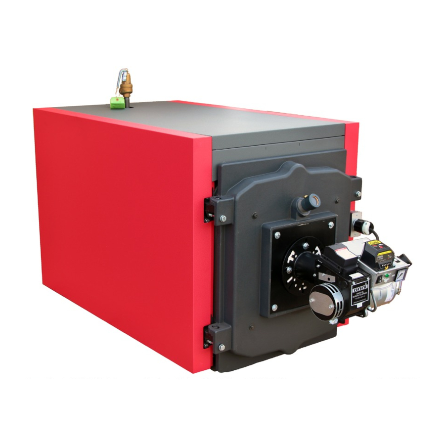
BOILER SPECIFICATIONS Figure 6 –Boiler (OWB-35 & OWB-50) OWB series boilers are three pass Scotch Marine design with fully water backed transfer surfaces. Boilers are designed for use in forced hot water heating systems. Heating is supplied by a Waste Oil Burner that burns all petroleum products any weight combination up to SAE 90W as well as fuel oils. -
Page 12: Standard Equipment
CODE REQUIREMENTS Installations must comply with all state, local, and utility codes, laws, regulations, and ordinances, and CSA standard B139. Where required by the authority having jurisdiction, the installation must conform to American society of Mechanical Engineers Safety Code for Controls and Safety Devices for Automatically Fired Boilers, No. CSD- All electrical wiring must be done in accordance with the National Electrical codes latest edition and all state and local codes. - Page 13 Centerline Of Burner Plate 36” 17” 33” Approx. 14” OWB-35 and OWB-50 Specifications 26” 12-1/4” 25” OWB-9, OWB-15, and OWB-25 Specifications Output Boiler Burner Input Capacity Model BTU’s BTU’s OWB-9 90,000 76,500 OWB-15 150,000 127,500 OWB-25 250,000 212,500 OWB-35 350,000 297,500 OWB-50 500,000...
-
Page 14: Combustion Air Supply
COMBUSTION AIR SUPPLY Failure to provide an adequate supply of fresh air for combustion will result in hazardous If you use a fireplace or a kitchen or bathroom exhaust fan, you should install an outside air intake. These devices will rob the boiler and water heater of combustion air. 1. - Page 15 (b) All Air From Outdoors: The confined space shall be provided with two permanent openings, one within 12 inches of the top and another within 12 inches of the bottom of the enclosure. The openings shall communicate directly, or by ducts, with the outdoors or crawl or attic spaces which communicate freely with the outdoors.
-
Page 16: Chimney Or Vent Requirements
All wall openings directly to outdoors must be screened to prevent entry by birds or small With Horizontal Ducts See Figure 10. *If the equipment room is located against an outside wall and the air openings communicate directly with the outdoors, each opening shall have a free area of not less than one square inch per 4,000 Btu per hour of the total input rating of all equipment in the enclosure. - Page 17 3. Breeching • See Table 2 for minimum recommended breeching and chimney sizes. • Keep run boiler to chimney as short as possible. • Use as few elbows as possible. • Slope upward towards chimney at not less than 1/4” per foot. •...
-
Page 18: Locating The Boiler
SIDE-WALL VENTING---IMPORTANT NOTE Two problems arise when side wall venting any oil appliance; There is sometimes an accelerated rate at which soot builds up on the cad-cell, spinner, etc. There is the potential for severe soot damage to the side of the structure in the event that the boiler operates at a high smoke level. -
Page 19: Installing The Boiler
INSTALLING THE BOILER Placing The Boiler (OWB-9 – OWB-25) 1. Move the boiler as close as possible to its final location in the crate. 2. Remove the two lag screws holding the rear feet to the skid. 3. Remove the front jacket panel. Cut the band holding the front of the boiler to the skid. -
Page 20: Installing Boiler Controls And Accessories
Pitch Up 1/4” per foot Barometric Draft Control Figure 12. INSTALLING THE BOILER CONTROLS AND Accessories for Boilers OWB-9, OWB-15, and OWB-25: a) Take the L8148A Aquastat relay, the well, the pressure relief valve with pipe nipple and the temperature/pressure gauge from the large carton which was packed in the wirebound crate. - Page 21 Remove the circulating pump from its carton in the crate and mount it to the pump flange on the end of the return manifold. Bare Boiler: The pressure relief valve and temperature/pressure gauge are supplied with the boiler and should be mounted as shown in Figure 13. The bare boiler does not include the return manifold.
-
Page 22: Water Piping Connections
WATER PIPING CONNECTIONS OWB-9, OWB-15, and OWB-25 boilers are shipped complete with circulating pump. To make the piping connections to the boiler ready to connect to the system piping, the following will also be required at a minimum: 1 – Air Purger (same size as supply pipe) 1 –... - Page 23 Closed Type Expansion Tank Supply System Shutoff Valve Cold Water Feed Fill Valve Return From System Circulation Pump Figure 16. (b) Piping connections with diaphragm expansion tank--- See Figure 17. The cold water feed to the pressure reducing fill valve may be piped with 1/2 inch pipe.
-
Page 24: System Piping
Supply and return and system piping should be sized by determining the pressure drop, required flow rate and pump capacity. Discharge piping from relief valve must be piped to a drain or must terminate 6” above floor to eliminate damage to the structure or personal injury. It must not be piped to a point where freezing might occur. - Page 25 Isolation Valves Flow Control Valves Isolation Valves Figure 19. MULTIPLE ZONING WITH CIRCULATORS ----- Each pump will require a separate relay (Honeywell R845A or White Rodgers 829A- 845, or equivalent). Install a flow control valve in each zone including the indirect water heater to prevent gravity circulation.
- Page 26 Return from System Supply to System Stem Thermometer Circulating Pumps Bypass A Circulating Pumps Adjust the two manual valves to maintain 160 degree F or more in the boiler while holding the supply water temperature at the stem thermometer at 140 degree F or whatever minimum temperature system requires. Figure 20.
- Page 27 Supply to System Shutoff Valve Cold Water Feed Return from System Circulating Pumps Adjust the two manual valves to maintain 135 degree F or more in the boiler with return water at the lowest temperature to be expected. Figure 21. INTEGRATED SYSTEM (HEAT AND DOMESTIC HOT WATER) ----- With a single heating zone priority for domestic hot water may be provided through the use of a 3-port zone valve.
- Page 28 Supply to System Shutoff Valve 3 Port Zone Valve Return from System Figure 22. INTEGRATED SYSTEM WITH MULTIPLE HEATING ZONES AND NO PRIORITY FOR DOMESTIC HOT WATER, USING ZONE VALVES----- Where the boiler output is large relative to the heating capacity of the coil in the indirect water heater priority for domestic hot water is not necessary.
- Page 29 Supply to System Zone Valves Return from System Figure 23. INTEGRATED SYSTEM, SINGLE OR MULTIPLE HEATING ZONES, USING CIRCULATING PUMPS RATHER THAN ZONE VALVES---- Each pump will require a separate relay (Honeywell R845A or White Rodgers 828A- 845, or equivalent). Install a flow control valve in each zone including the indirect water heater to prevent gravity circulation.
- Page 30 COMBINATION HEATING/COOLING SYSTEM WITH CHILLED WATER The chiller must be piped in parallel with the boiler and isolation valves installed to prevent the chilled water from circulating through the boiler and heated water from circulating through the chiller. See Figure 25. Insulation Valve # 4 Supply to System Insulation...
- Page 31 Size Secondary Pump GPM at Gross Boiler Output for 20” Drop. When Calulating Pump Head, the Maximum Boiler Resistance for any Boiler will not Exceed 14 in. W.C. Head. System Return Figure 27. Installation, Operation, And Service Instructions Amtrol #720 Air Eliminator or Equal System Supply Separator System Circulator...
- Page 32 11. MULTIPLE BOILER PIPING- REVERSE RETURN FLOW WITH BLEND PUMP *Blend Pump Check Valve System Return Figure 28. Amtrol #720 Air Eliminator or Equal Check Valve Air Separator *Blend Pump Expansion Tank Installation, Operation, And Service Instructions System Supply System...
-
Page 33: Burner Mounting
BOILER ASSEMBLY & WIRING When the burner is field installed the installer must fill in the space between the burner blast tube and the insulation block on the inside of the burner door with refractory mix provided. Figure 29. OWB-35 and OWB-50 Burner Mounting & Boiler Door Detail Figure 30. - Page 34 Boiler Jacket Assembly Sight Class Assy Figure 31. OWB-35 and OWB-50 Assembly Detail OWB-35 and OWB-50 Jacket Installation Instructions 1. Screw the four extension setscrews (43) into the four outer holes in the corners of the rear sections. Securely tighten the setscrews and other fastening bolts of the flue outlet cover (22) 2.
- Page 35 8. Hook center panel (33) with flange edge down between side panels (93) and (94). 9. Attach the upper front trim panel (41) between the right and left side panels over the front door. 10. Place the top panel (86) in position. Hook to the side panels. 11.
- Page 36 5. Attach one door bracket (18) to the bottom of both the left and right side jacket panels. Use two 8-32x1/2” screws (19) and nuts (20) to assemble each door bracket. 6. Attach the left and right side jacket panels to the boiler. The front end of the right side panel is attached to the hinge using 10-24x3/4 screws (21).
- Page 37 All wiring and grounding must be done in accordance with the authority having jurisdiction or, in the absence of such authority, with the National Electrical Code (ANSI/NFPA70). 1) 120 Volt Wiring—The boiler should be provided with its own 20A branch circuit with fused disconnect.
- Page 38 thermostat connections so that any zone valve that opens will also start the circulator and fire the boiler(assuming the high limit is not open). Zone valve terminal TH/TR has no internal connection on the zone valve; it is merely a “binding post” used to connect two or more wires.
- Page 39 Figure 33. WIRING DIAGRAM, SINGLE HEATING ZONE ONLY Installation, Operation, And Service Instructions...
- Page 40 Figure 34. WIRING DIAGRAM, SINGLE HEATING ZONE ONLY (BOILERS EQUIPPED WITH BURNER DOOR DISCONNECT SWITCH) Installation, Operation, And Service Instructions...
- Page 41 Figure 35. WIRING DIAGRAM, ZONE WIRING USING HONEYWELL V8043F VALVES (FACTORY BOILER WIRING NOT SHOWN –SEE FIGURE 33 OR 34) Figure 36. WIRING DIAGRAM, CIRCULATOR ZONE WIRING USING HONEYWELL R845A’S (FACTORY DIAGRAM WIRING NOT SHOWN –SEE FIGURE 33 OR 34) Installation, Operation, And Service Instructions...
-
Page 42: Boiler Startup And Adjustments
BOILER START-UP AND ADJUSTMENTS 1. Close manual air vents (if used) and automatic air vents. Attach hose to boiler drain on return connection and run to a drain or to outdoors. Open drain cock and close shutoff valve on boiler supply pipe. 2. -
Page 43: Waste Oil Burner Startup
WASTE OIL BURNER STARTUP DO NOT fire boiler without water or boiler sections will overheat and eventually crack 6. IMPORTANT- Prior to starting the unit, pre-fill the filter and fuel line with oil to assist priming procedure. Oil pump motor turns at low RPM’s and would take significant time to complete priming process if not pre-filled. -
Page 44: Maintenance
WASTE OIL BURNER: 1. Weekly Drain water from storage tank. 2. Monthly Clean pump screen on oil pump assembly of sludge and remove any water. Access to screen is by removing pump cover. Clean flame cone of deposits. 3. Yearly Inspect and adjust electrodes per (figure 37). CAUTION: turn off main electrical power before checking or adjusting electrode settings. - Page 45 Figure 37 –Electrode Adjusment Diagram When cleaning, inspect all three pieces thoroughly. When disassembling and reassembling nozzle, keep facing up as shown. Figure 38 –Nozzle Assembly Detail Installation, Operation, And Service Instructions...
-
Page 46: Trouble Shooting Guide
TROUBLE-SHOOTING GUIDE NO HEAT: 1. Check burner power switch and make sure power is available to the whole control system. 2. If included in system, check low-water cutoff and/or manual reset high limit. 3. Check room thermostat(s) and zone valves or pump relays (if used). 4. -
Page 47: Warranty
Omni Waste Oil Boilers Econo Heat (manufacturer) warrants to the purchaser of Waste Oil Boilers will be free from defects in materials and workmanship for the durations specified below, which duration begins on the date of delivery to the customer. Customer is responsible for maintaining proof of date of delivery. If return is deemed necessary for warranty evaluation and determination of repair or replacement, boiler is to be sent to the factory with freight prepaid. - Page 48 Installation, Operation, And Service Instructions...
-
Page 49: Warranty Card
WARRANTY CARD Please fill our, tear off and return to manufacturer Return following warranty information to manufacturer within thirty (30) days of purchase or warranty will not be valid. (Please print or type). Date of Purchase_____________________________________________________________________ Serial #__________________________ Model ____________________________________________ Customer Name_____________________________________________________________________ Address____________________________________________________________________________ City _________________________ State ________________ Zip Code ________________________...
Need help?
Do you have a question about the OWB Series and is the answer not in the manual?
Questions and answers