Carrier Performance 38QRR Installation Instructions Manual
Performance series with puron refrigerant 1-1/2 to 5 nominal tons
Hide thumbs
Also See for Performance 38QRR:
- Installation instructions manual (10 pages) ,
- Owner's information manual (6 pages) ,
- Product data (43 pages)
Advertisement
38QRR
Performance™ Series Heat Pumps
with PURONr Refrigerant
1---1/2 to 5 Nominal Tons
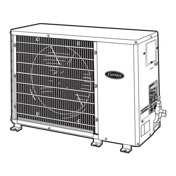
Fig. 1 --- 38QRR
NOTE: Read the entire instruction manual before starting the
installation.
TABLE OF CONTENTS
. . . . . . . . . . . . . . . . . . . . . . . . . . . . . . . . .
. . . . . . . . . . . . . . . . . . . . . . . . . . . . . .
. . . . . . . . . . . . . . . . . . . . . . . . . . . . . . . . . . . . . . . .
. . . . . . . . . . . . . . . . . . . . . . . . . . . . . . . . . . . . . . . . .
. . . . . . . . . . . . . . . . . . . . . . . . . . . . . . . . . . .
. . . . . . . . . . . . . . . . . . . . . . . . . . .
Installation Instructions
PAGE
. . . . . . . . . . . . . . . . . . . . . . . .
. . . . . . . . . . . . . . . . . . .
. . . . . . . . . . . . .
. . . . . . . . . . . . . . . . . . . . . . . .
SAFETY CONSIDERATIONS
Improper installation, adjustment, alteration, service, maintenance,
or use can cause explosion, fire, electrical shock, or other
conditions which may cause death, personal injury, or property
damage. Consult a qualified installer, service agency, or your
distributor or branch for information or assistance. The qualified
installer or agency must use factory- -authorized kits or accessories
when modifying this product. Refer to the individual instructions
packaged with the kits or accessories when installing.
Follow all safety codes. Wear safety glasses, protective clothing,
and work gloves. Use quenching cloth for brazing operations.
Have a fire extinguisher available. Read these instructions
thoroughly and follow all warnings or cautions included in
literature and attached to the unit. Consult local building codes and
the current editions of the National Electrical Code (NEC)
NFPA70.
In Canada, refer to the current editions of the Canadian Electrical
A07532
Code CSA C22.1.
Recognize safety information. This is the safety- -alert symbol
When you see this symbol on the unit and in instructions or
manuals, be alert to the potential for personal injury. Understand
the signal words DANGER, WARNING, and CAUTION. These
words are used with the safety- -alert symbol. DANGER identifies
the most serious hazards which will result in severe personal injury
1
or death. WARNING signifies hazards which could result in
personal injury or death. CAUTION is used to identify unsafe
2- -3
practices which may result in minor personal injury or product and
2
property damage. NOTE is used to highlight suggestions which
2
will result in enhanced installation, reliability, or operation.
3
!
3
4
ELECTRICAL SHOCK HAZARD
5
Failure to follow this warning could result in personal injury
or death.
7
Before installing, modifying, or servicing system, main
9- -10
electrical disconnect switch must be in the OFF position.
There may be more than 1 disconnect switch. Lock out and
tag switch with a suitable warning label.
!
ENVIRONMENTAL HAZARD
Failure to follow this caution may result in environmental
pollution.
Remove and recycle all components or materials (i.e. oil,
refrigerant, etc.) before unit final disposal.
WARNING
CAUTION
.
Advertisement
Table of Contents

Related Manuals for Carrier Performance 38QRR


Summary of Contents for Carrier Performance 38QRR
-
Page 1: Table Of Contents
National Electrical Code (NEC) NFPA70. In Canada, refer to the current editions of the Canadian Electrical A07532 Fig. 1 --- 38QRR Code CSA C22.1. Recognize safety information. This is the safety- -alert symbol NOTE: Read the entire instruction manual before starting the When you see this symbol on the unit and in instructions or installation. -
Page 2: Installation
The 38QRR heat pump units can be matched to corresponding enclosed area, ensure there is adequate ventilation to prevent indoor units. The 38QRR unit can be matched with under- -ceiling recirculation of discharge air. and residential fan coils and evaporator coils. Refer to separate Operating Ambient indoor unit literature for more information. -
Page 3: Complete Refrigerant Piping Connections
Field- -fabricated snow or ice stands may be used to raise unit when operation will be required during winter months. Units may also be wall mounted using the accessory wall mounting kit. A05227 Fig. 4 --- Filter Drier Components The filter drier must be replaced whenever the refrigeration system is exposed to the atmosphere. -
Page 4: Start- -Up
OFF and indoor blower has NOTE: Operating unit on improper line voltage constitutes abuse stopped. and could affect Carrier warranty. See Product Data. Do not install unit in a system where voltage may fluctuate above or below Power Wiring permissible limits. -
Page 5: Service
-fan motor failure, system restriction, etc. It opens on pressure rise at about 650 ± 10 psig. If system pressures go above this setting during abnormal conditions, the switch opens. 38QRR Unit Size, in. (mm) WARNING 018,024 030,036 048,060 0.433 (11.00) - Page 6 Service Valves The service valves in the outdoor unit come from the factory frontseated. This means the refrigerant charge is isolated from the line- -set connection ports. To prevent damage to the valve, use a wet cloth or other accepted heat sink material on the valve before brazing.
-
Page 7: Maintenance
If the indoor temperature is below 70_F (21_C), or the outdoor Recovery cylinder service pressure rating must be 400 temperature is not in the favorable range, adjust charge for line set psig, DOT (Department of Transportation) 4BA400 or length above or below 15 ft (4.6 m) only. Charge level should then DOT BW400. - Page 8 coil sections. Dirt and debris may pass through first section, 2. Using a garden hose or other suitable equipment, flush coil become trapped between the row of fins and restrict condenser from the outside to remove dirt. Be sure to flush all dirt and airflow.
-
Page 9: Troubleshooting
TROUBLESHOOTING LEGEND — Normally Closed ODT — Outdoor Thermostat NOTE: For systems with indoor units equipped with microprocessor control, see separate controls, service, and troubleshooting manual. A07435 Fig. 10 --- Troubleshooting the Cooling Cycle... - Page 10 A07436 Fig. 11 --- Troubleshooting the Heating Cycle Catalog No: 38QRR ---5SI Copyright 2009 Carrier Corp. S 7310 W. Morris St. S Indianapolis, IN 46231 Printed in U.S.A. Edition Date: 01/09 Manufacturer reserves the right to change, at any time, specifications and designs without notice and without obligations.
Need help?
Do you have a question about the Performance 38QRR and is the answer not in the manual?
Questions and answers