Table of Contents
Advertisement
Advertisement
Table of Contents

Related Manuals for URC MRX-2

Summary of Contents for URC MRX-2
- Page 1 MRX-2 Owner’s Manual Network Base Station...
- Page 2 MRX-2 Owner’s Manual ©2013 Universal Remote Control, Inc. The information in this manual is copyright protected. No part of this manual may be copied or reproduced in any form without prior written consent from Universal Remote Control, Inc. UNIVERSAL REMOTE CONTROL, INC. SHALL NOT BE LIABLE FOR OPERATIONAL, TECHNICAL OR EDITORIAL ERRORS/OMISSIONS MADE IN THIS MANUAL.
-
Page 3: Table Of Contents
ABLE ONTENTS Introduction Features and Benefits Parts Guide Front and Rear Panel Descriptions Network Installation Specifications USA Limited Warranty Statement Federal Communication Commission Interference Statement Declaration of Conformity... -
Page 4: Introduction
Control URC RF Lighting using the optional RFTX-1 transmitter. When used in a Complete Control System: The MRX-2 is required to use the CC Control App for iOS devices, like the iPad and iPhone. Extend control to other rooms by installing multiple MRX-2’s throughout the home or commercial space. -
Page 5: Features And Benefits
Components located out of reach from the MRX Advanced Network System Controller may be controlled via IR, RS-232 or Relays by using an MRX-2 to expand the scope of a Total Control system. Lighting Control: By connecting an optional RFTX-1 RF Transmitter, take control of your URC lighting (within range). -
Page 6: Parts Guide
MRX-2 N ETWORK TATION Parts Guide The MRX-2 Network Base Station includes: 1 - MRX-2 Network Base Station 1 - Two Meter 3.5mm Stereo to 1 - 12V-1000mA Power Supply 3.5mm Stereo (for daisy chaining 6 - Visible Emitters with 10 foot plug... -
Page 7: Front And Rear Panel Descriptions
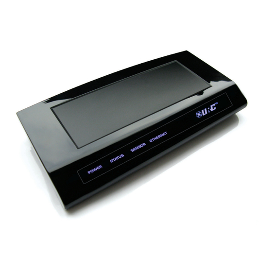
Status: Flashes blue when an RF or Network signal is received. Sensor: Illuminates to indicate when the sensor is activated. Ethernet: Illuminates when connected to an active network. Reset: Press the Reset button located under the MRX-2 to restart the unit. Page 4... - Page 8 Sensor: Connect with one of URC’s or compatible third party, sensors. IR IN: Allows MRX-2 control from a base station such as a MRF-260. Note:IR Routing is lost from commands received from this input. IR Outputs: Connect emitters for IR control of connected devices.
-
Page 9: Network Installation
ETWORK TATION Network Installation The MRX-2 can be installed in either a Total Control or a Complete Control System. Connect the Ethernet cable (RJ45) to the rear of the MRX-2 and the other end to the active network. Total Control Install... -
Page 10: Specifications
MRX-2 N ETWORK TATION Specifications Network: One 10/100 Ethernet port Relay: One relay configurable to be NO, NC or Momentary Sensor: One sensor supports Video or Voltage sensing via URC sensors. RS-232: Two RS-232 ports support TX, RX and GND two way communication via URC cables. -
Page 11: Usa Limited Warranty Statement
UNIVERSAL REMOTE CONTROL, INC. warrants this product against defects in material or workmanship for a period of one (1) year and as set forth below. Universal Remote Control will, at its sole option, repair the product using new or comparable rebuilt parts, or exchange the product for a comparable new or rebuilt product. - Page 12 MRX-2 N ETWORK TATION LIMITATION OF REMEDIES UNIVERSAL REMOTE CONTROL SHALL NOT BE LIABLE FOR ANY INCIDENTAL OR CONSEQUENTIAL DAMAGES FOR BREACH OF ANY EXPRESS OR IMPLIED WARRANTY OR CONDITION ON THIS PRODUCT. IN NO EVENT SHALL UNIVERSAL REMOTE CONTROL...
-
Page 13: Federal Communication Commission Interference Statement
MRX-2 N ETWORK TATION Federal Communication Commission Interference Statement This equipment has been tested and found to comply with the limits for a Class B digital device, pursuant to part 15 of the FCC Rules. These limits are designed to provide reasonable protection against harmful interference in a residential installation. -
Page 14: Declaration Of Conformity
List of test reports and/or certificate verified compliance with the standards above n EMC Directive l Report No. l Testi ng Labora tory : Gumi College EMC Center Date of issue January 30, 2013 James Novak Name and signature of authorized person Senior Product Manager Universal Remote Control Inc. Page 11... - Page 16 500 Mamaroneck Avenue, Harrison, NY 10528 Phone: (914) 835-4484 Fax: (914) 835-4532 www.universalremote.com OCE-0076D Rev 01...
Need help?
Do you have a question about the MRX-2 and is the answer not in the manual?
Questions and answers