Table of Contents
Advertisement
Advertisement
Table of Contents

Summary of Contents for Celestica A2210
- Page 1 A2210 User’s Manual...
- Page 3 A 2 2 1 0 User’s Manual SS030616-06 Celestica 9 Northeastern Boulevard Salem, NH 03079...
- Page 4 Celestica retains the right to make changes to any information included in this manual, without the need to notify other parties, or to make changes in the product or manuals already distributed.
-
Page 5: Table Of Contents
1.4.3 USB Ports 1.4.4 External SCSI 1.4.5 Ethernet Internal Connectivity 1.5.1 Mass Storage Contacting Celestica 1-10 Chapter 2 - INSTALLATION Unpacking the System Before Powering On the System 2.2.1 Inspect the Server 2.2.2 Install Slide Rails Powering On the System Chapter 3 –... - Page 6 Operating Precautions Chapter 5 – MOTHERBOARD SET-UP Adding/Replacing Dual Inline Memory Modules 5.1.1 Installation Procedure 5.1.2 Removal Procedure Replacing the Processors and Heatsinks Setting the Switches Replacing the Motherboard Chapter 6 – CHASSIS SET-UP Replacing the Signal Interface Board Replacing the Server Management Board Replacing Dual-Channel SCSI Controller Board Replacing the Front Access Panel Board Replacing the PCI Riser Card...
- Page 7 Appendix B - CONNECTOR ASSIGNMENTS External Connectors VHDCI SCSI Connector PS/2 Keyboard and Mouse Connector Serial Port Connector USB Connector Internal Connectors 68-Pin SCSI Connector SCSI SCA Connector EIDE Port 64-Bit PCI Connectors 32-Bit PCI Connectors...
-
Page 9: Chapter 1 - Introduction
A2210 server. This document also supplies general system operation information. 1.1 Overview The A2210 server is 1U platform based on AMD Opteron™ processors and AMD HyperTransport chipsets. The feature sets are targeted for OEM and system builder markets. Table 1 presents the primary hardware components used on the A2210 platform. - Page 10 U S E R ’ S M A N U A L Function Component PCI-X Tunnel AMD-8131. HyperTransport PCI-X Tunnel • One 16x16 HyperTransport I/O bus interface • One 8x8 HyperTransport I/O bus interface • Two PCI-X bridges and bus interfaces Peripheral Bus AMD-8111.
-
Page 11: Feature Identification
U S E R ’ S M A N U A L 1.2 Feature Identification This section provides a series of drawings to familiarize the user with the many features of the server. Mouse Keyboard External Ultra320 SCSI Port USB 1.1 Gigabit Ethernet Ports (2) BMC Management Port PCI-X Card External Connectors... - Page 12 U S E R ’ S M A N U A L CD-ROM Drive Hard Drives LAN Activity USB 1.1 Serial Port Fault Indicator IDE Activity Power Switch Reset Switch Power Indicator Figure 2 - Front View - External Features...
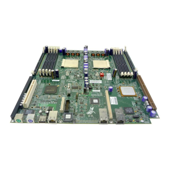
- Page 13 U S E R ’ S M A N U A L PCI-X Riser Board Slot DIMM Slots (4) Dual-Channel SCSI Controller Board Processor H0 Server Management Board Processor H1 Video Board DIMM Slots (4) Signal Interface Board Figure 3 – Interior Features...
-
Page 14: Server Architecture
Figure 4 is a block diagram of the server’s electrical components. 1.3.1 Main Board The main board is the central hub for the A2210 platform on which most major system devices reside and to which all peripheral boards connect. -
Page 15: Pci-X Riser Board
U S E R ’ S M A N U A L 1.3.6 PCI-X Riser Board The PCI-X riser board allows the A2210 to have connectivity for two full length 64- bit, 100MHz PCI-X cards. Figure 4 - A2210 Server Block Diagram... -
Page 16: External Connectivity
The following are features of the USB ports used on the A2210 server: • Single USB 1.1 port is mounted on the back panel I/O and routed to the AMD-8111 I/O hub. -
Page 17: External Scsi
Internal connectivity includes all interfaces internal to the chassis that provide connection to other devices internal or external to the chassis that are part of the A2210 server feature set. These interfaces include EIDE and floppy storage devices, front panel connections, and other miscellaneous connectors. -
Page 18: Contacting Celestica
U S E R ’ S M A N U A L The A2210 server contains two methods implemented for cable type detection. The two different cable types (40 or 80 conductor) dictate the overall transfer rate ability of the host or bus. Transfer rates greater than Ultra DMA 2 require an 80-conductor cable. -
Page 19: Chapter 2 - Installation
hapter U S E R ’ S M A N U A L Installation Unpacking and Set-Up he server is delivered in packaging designed to protect it from the stress of shipping. It is recommended that this packaging be saved and reused should the server need to be transported to another location. -
Page 20: Before Powering On The System
U S E R ’ S M A N U A L 2.2 Before Powering On the System Prior to applying power to the server for the first time, please perform the following procedures. 2.2.1 Inspect the Server Open the chassis and perform a visual inspection. Remove the cover lock down screws located on the rear of the chassis. - Page 21 U S E R ’ S M A N U A L Retainer Latch Stop Tab Keyhole Slots Figure 6 – Smallest Beam Features Screw Hole for Securing Beam Figure 7 – Screw Hole 3. Place the outer member slide beams into the desired rack position and fully extend against the rack vertical rails.
-
Page 22: Powering On The System
U S E R ’ S M A N U A L 6. Reassemble the rail by sliding the outer two beams over the smaller beam starting from the rear of the server and duplicating the original factory orientation. It may be necessary to release the retainer latch during this process. -
Page 23: Chapter 3 - System Interfaces
Chapter U S E R ’ S M A N U A L System Interfaces Switches, LEDs, and more . . . his chapter provides details on the switches, buttons, and LEDs that a user will need to know for proper operation of the server. 3.1 Switches/Buttons There are two switches on the front of the server - the Reset and Power buttons. -
Page 24: Control Panel Leds
U S E R ’ S M A N U A L 3.2 Control Panel LEDs There are four LEDs that are visible through the front panel, as listed in Table 3. Table 3. LED Definitions LED Name Functional Description Power Indicates the full on state when lit. -
Page 25: Chapter 4 - Safety
Chapter U S E R ’ S M A N U A L Safety Overview and Features lease note the following essential safety information before installing the server and while using it. Caution This equipment must be serviced only by qualified personnel. 4.1 General Precautions Follow these rules to ensure general safety: •... -
Page 26: Electrical Precautions
U S E R ’ S M A N U A L • Close the system and (if rack-mounted) secure it to the rack unit with the retention screws after ensuring that all connections have been made. 4.2 Electrical Precautions Follow basic electrical safety precautions to protect persons from harm and the server from damage. -
Page 27: Operating Precautions
U S E R ’ S M A N U A L • Touch a grounded metal object before removing the board from the antistatic bag. • Do not let components or PCBs come into contact with clothing, which may retain a charge even if you are wearing a wrist strap, since permanent damage can occur to the system. - Page 28 U S E R ’ S M A N U A L...
-
Page 29: Chapter 5 - Motherboard Set-Up
Chapter U S E R ’ S M A N U A L Motherboard Set-up Making Changes his section describes the server motherboard configurations, including options that can be changed to improve performance in particular applications. 5.1 Adding or Replacing the Dual Inline Memory Modules The main board has two banks of DIMM slots. -
Page 30: Removal Procedure
DIMM. 5.2 Replacing the Processors and Heatsinks The A2210 system is designed to work with an AMD Opteron™ processor in a 940-pin package. Typically a A2210 system is populated with two processors, but it is also possible to operate the server using only one processor. In this case, the processor is placed in the H0 slot, which is the slot on the left when the chassis is viewed from the front. - Page 31 U S E R ’ S M A N U A L 2. The heatsinks are each held in place by a clip that is anchored by two screws. Remove the screws as shown in Figure 9. When the clip is unscrewed, the heatsink and lid will still be stuck to each other.
- Page 32 U S E R ’ S M A N U A L Figure 10 - Releasing the Processor Installation Procedure To install the processor, follow these steps: 1. Clean the surfaces of the processor lid and heatsink. Gently scrape off all excess thermal interface material with a flat, plastic edge.
-
Page 33: Setting The Switches
M A N U A L 5.3 Setting the Switches Refer to Figure 11 for the location of SW3 on the A2210 main board. Ensure that the following switch is set: SW3: 12345678=OFF ON OFF OFF OFF OFF OFF OFF SW4: Don’t care... -
Page 34: Replacing The Motherboard
M A N U A L 5.4 Replacing the Motherboard There are several other components that must be taken out before the A2210 motherboard can be removed. Follow these steps to remove the motherboard: 1. Remove the heatsinks, Dual-Channel SCSI Controller Board, Signal Interface Board, video card, Server Management Board, and the PCI-X cage. -
Page 35: Chapter 6 - Chassis Set-Up
M A N U A L Chassis Set-up Changing Configurations his section describes the server chassis configurations, including the default settings as well as options that can be changed to improve performance in particular applications. Figure 12 – A2210 Server... -
Page 36: Replacing The Signal Interface Board
U S E R ’ S M A N U A L 6.1 Replacing the Signal Interface Board The signal interface board can be removed by lifting it straight out. The fit between the pins on signal interface board and the two sockets on the motherboard is tight. Rocking the signal interface board back and forth while pulling helps to loosen it from the motherboard to give the user’s hands more room. -
Page 37: Replacing Dual-Channel Scsi Controller Board
U S E R ’ S M A N U A L Correct Mounting Hole Figure 14 – Replacing the Video Card 6.3 Replacing the Dual-Channel SCSI Controller Board The dual-channel SCSI controller board is held in place by two screws. Take the screws out, and then the card can be removed. - Page 38 U S E R ’ S M A N U A L Figure 15 - Removing Power and Fan Cables Disconnect the hard drives from the front access panel board. Disconnect the cables if an IDE hard drive is used, or ejecting the hard drive if the system is SCSI based.
-
Page 39: Replacing The Pci Riser Card
6.5 Replacing the PCI Riser Card The A2210 uses one of two PCI riser cards – one that supports two PCI-X cards, or one that only supports one. It is preferable to use the single-card riser if only one PCI-X card is used in a system. -
Page 40: Replacing The Pci-X Cards
Replace all PCI-X cards. 6.6 Replacing the PCI-X Cards The A2210 system can support up to two PCI-X cards. The PCI-X cards are contained within a cage in the rear of the chassis. 1. The cage is not held in place by any screws, so it can be lifted straight out after moving the SCSI cable connected to Dual-Channel SCSI Controller Board out of the way, as shown in Figure 18 and Figure 19. - Page 41 U S E R ’ S M A N U A L Figure 18 - Moving the SCSI Cable Figure 19 - Moving the PCI Cage...
- Page 42 U S E R ’ S M A N U A L 2. Once the cage is removed, take out the PCI-X cards by removing the screw holding each card in place as shown in Figure 19. Figure 20 - Removing a PCI-X Card 3.
-
Page 43: Eide Cabling
M A N U A L 6.7 EIDE Cabling The A2210 platform presents a unique EIDE solution to an end user. The primary EIDE channel is located on the chassis front board, while the secondary EIDE channel is located on the chassis sideboard. The appropriate usage of EIDE cables is critical for proper and optimal performance of devices connected to the primary and secondary EIDE channels. -
Page 44: Replacing The Ide Disk Drives
U S E R ’ S M A N U A L 6.8 Replacing the IDE Disk Drives Hard drives and floppy disk drives are located near the front of the chassis on the right side. IDE and SCSI drives are held in different drive cages. The difference between the cages is that the IDE drive cage is designed to be rigidly held in place with a screw, while the SCSI drive cage is designed for a hot-swappable drive so that it can be taken out without opening the chassis. - Page 45 U S E R ’ S M A N U A L Figure 22 - Removing the IDE Drive Cage 4. Pull out the IDE drive cage from the front of the chassis. 6-11...
-
Page 46: Removing The Scsi Drive Cage
U S E R ’ S M A N U A L 6.8.2 Removing the SCSI Drive Cage To remove a SCSI drive cage, pull the latch in the front of the drive cage, and then pull the drive cage out of the front of the chassis as shown in Figure 23. Figure 23 - Removing the SCSI Drive Cage 6.8.3 Removing the Drive from the Drive Cage After removing an IDE or SCSI drive cage, the hard drive itself can be taken out of... -
Page 47: Removing The Cd Or Dvd Drive
U S E R ’ S M A N U A L 6.8.4 Removing the CD or DVD Drive The CD or DVD drive is held in place by a wire clip. This can be removed by stretching the clip free of the drive cage, as shown in Figure 24. Figure 24 - Removing Clip from the CD Drive 6-13... - Page 48 U S E R ’ S M A N U A L 6-14...
-
Page 49: Chapter 7 - Bios
hapter U S E R ’ S M A N U A L BIOS Upgrades, Clearing, and Screens his chapter describes the BIOS configurations, including the default settings as well as options that can be changed to improve performance in particular applications. - Page 50 U S E R ’ S M A N U A L • Supports ACPI Power states C0, C1, S0, and S5 • Supports Zircom UL BMC and IPMI 1.5 specification • Integrates option ROM and PXE ROM to support on-board Gigabit NIC •...
-
Page 51: Clearing The Cmos Bios
U S E R ’ S M A N U A L 7.2 Clearing the CMOS BIOS Before debugging any board issue, clear the CMOS by following these steps: 1. Press the power button on the front access panel board for four seconds to power down the system. -
Page 52: Flashing New Bios
U S E R ’ S M A N U A L 7.3 Flashing New BIOS Follow these steps to flash a new BIOS: 1. Create a bootable CD, copy the new BIOS image onto it, and insert it into the CD-ROM drive. -
Page 53: Bios Screenshots
U S E R ’ S M A N U A L 7.4 BIOS Screenshots Below are a series of snapshots that are representative of the major screens taken from the A2210 BIOS. - Page 54 U S E R ’ S M A N U A L...
- Page 55 U S E R ’ S M A N U A L...
- Page 56 U S E R ’ S M A N U A L...
- Page 57 U S E R ’ S M A N U A L...
- Page 58 U S E R ’ S M A N U A L 7-10...
-
Page 59: Appendix A - Technical Specifications
Appendix U S E R ’ S M A N U A L Technical Specifications Electrical Rating: 2.5Amps@100Vac; 1.0Amps@240Vac Weight: 30 lbs Dimensions: Height: 1.7 inches; Width: 17 inches; Depth: 28 inches Safety Certifications: CSA 22.2 #950-95; EN60950 FCC Compliance Statement This equipment has been tested and found to comply with the limits for a Class A digital device, pursuant to part 15 of the FCC Rules. -
Page 60: Non-Operational Environment
U S E R ’ S M A N U A L Non-operational Environment Measurement Range Ambient temperature –30° to 60°C (–4° to 140°F) Relative humidity 5% to 95% (non condensing) Maximum wet-bulb temperature 38.7°C Shock 15 G, 10ms duration, X, Y, & Z axis orientations Vibration 0.75 G 5 –... -
Page 61: Appendix B - Connector Assignments
Appendix Connector Assignments This appendix defines the different connectors and pin assignments used externally and internally to the A2210 server. External Connectors VHDCI SCSI Connector The external SCSI connector is the Molex VHDCI SCSI connector, 71430 or equivalent, as shown in Figure 26. - Page 62 Name Description Name Description D1_H Data 1 + D1_L Data 1 - D2_H Data 2 + D2_L Data 2 - D3_H Data 3 + D3_L Data 3 - D4_H Data 4 + D4_L Data 4 - D5_H Data 5 + D5_L Data 5 - D6_H...
-
Page 63: Ps/2 Keyboard And Mouse Connector
PS/2 Keyboard and Mouse Connector The PS/2 keyboard and mouse use right-angle mini-DIN connectors with PC 99 standard coloring (violet for keyboard and light green for mouse), as shown in Figure 27. The pin assignments for the PS/2 connectors are listed in Table 5. Figure 27. -
Page 64: Serial Port Connector
Serial Port Connector The serial connector is a 9-pin right-angle Subminiature D male Connector, AMP 748879-1 or equivalent, as illustrated in Figure 28. The pin assignments for this connector are listed in Table 6. Figure 28. Serial Connector Table 6. Serial Connector Pin Assignments Name Description Carrier Detect... -
Page 65: Usb Connector
USB Connector There is one USB connector used on the A2210 server platform, the Molex 87531, shown in Figure 29. The pin assignments for the USB connector are listed in Table 7. Figure 29. USB Connector Table 7. USB Connector Pin Assignments... -
Page 66: Internal Connectors
The following connectors are internal connectors. 68-Pin SCSI Connector The SCSI connector used in the A2210 platform is the 68-pin Molex 15-87-0307, or equivalent, as shown in Figure 30. The pin assignments are listed in Table 8. Figure 30. 68-Pin SCSI Connector Table 8. - Page 67 Name Description Name Description Ground Ground ATN_H Attn + ATN_L Attn - Ground Ground BSY_H Busy + BSY_L Busy - ACK_H Acknowledge + ACK_L Acknowledge - RST_H Reset + RST_L Reset - MSG_H Message + MSG_L Message - SEL_H Select + SEL_L Select - CD_H...
-
Page 68: Scsi Sca Connector
SCSI SCA Connector Figure 31 shows the connector used to connect the SCSI drive to the SCSI backplane. It is Molex 73829 or equivalent. The pin assignments for this connector are listed in Table 9. Figure 31. SCSI SCA Connector Table 9. -
Page 69: Eide Port
Name Description Name Description D5_L Data 5 - D5_H Data 5 + D4_L Data 4 - D4_H Data 4 + D3_L Data 3 - D3_H Data 3 + D2_L Data 2 - D2_H Data 2 + D1_L Data 1 - D1_H Data 1 + D0_L... -
Page 70: 64-Bit Pci Connectors
Name Description Name Description Data 4 DD11 Data 11 Data 3 DD12 Data 12 Data 2 DD13 Data 13 Data 1 DD14 Data 14 Data 0 DD15 Data 15 Ground (KEY) Key (pin missing) DMARQ DMA Request Ground /DIOW Write Strobe Ground /DIOR Read Strobe... - Page 71 Table 11. 64-Bit PCI Connector Pin Assignments Name Description Name Description –12V –12 VDC TRST_L Test Logic Reset Test Clock +12V +12 VDC Ground Test Mode Select Test Data Output Test Data Input +5 VDC +5 VDC +5 VDC INTA_L Interrupt A INTB_L Interrupt B...
- Page 72 Name Description Name Description IRDY_L Initiator Ready Ground +3.3V +3.3 VDC TRDY_L Target Ready DEVSEL_L Device Select Ground Ground STOP_L Stop Transfer Cycle LOCK_L Lock bus +3.3V +3.3 VDC PERR_L Parity Error SMBCLK +3.3V +3.3 VDC SMBDAT SERR_L System Error Ground +3.3V +3.3 VDC...
-
Page 73: 32-Bit Pci Connectors
Name Description Name Description AD61 Address/Data 61 Ground +3.3V +V I/O (+3.3 V) AD60 Address/Data 60 AD59 Address/Data 59 AD58 Address/Data 58 AD57 Address/Data 57 Ground Ground AD56 Address/Data 56 AD55 Address/Data 55 AD54 Address/Data 54 AD53 Address/Data 53 +3.3V +V I/O (+3.3 V) Ground AD52... - Page 74 Figure 34. 32-Bit PCI Connector Table 12. 32-Bit PCI Connector Pin Assignments Name Description Name Description –12V –12 VDC TRST_L Test Logic Reset Test Clock +12V +12 VDC Ground Test Mode Select Test Data Output Test Data Input +5 VDC +5 VDC +5 VDC INTA_L...
- Page 75 Name Description Name Description Ground AD22 Address/Data 22 AD21 Address/Data 21 AD20 Address/Data 20 AD19 Address/Data 19 Ground +3.3V +3.3 VDC AD18 Address/Data 18 AD17 Address/Data 17 AD16 Address/Data 16 C/BE2_L Command, Byte Enable 2 A33 +3.3V +3.3 VDC GND13 Ground FRAME_L Address or Data phase...
Need help?
Do you have a question about the A2210 and is the answer not in the manual?
Questions and answers