
Related Manuals for G-Lenz Security 8304


Summary of Contents for G-Lenz Security 8304
-
Page 1: User Manual
H.264 NETWORK Embeded DVR 8304/8308) USER MANUAL Copyright 2005-2008, Streaming Video Technology, Co., Ltd All Rights Reserved... -
Page 2: Table Of Contents
CONTENT INTRODUCTION ........................3 Main Feature ........................3 Product features ......................... 3 1.2.1 Parameter ........................3 1.2.2 Basic working parameter ....................5 1.3 ENTIRONMENT ADAPTABILITY .................... 5 Device operation manual ......................6 Remote key instruction ....................... 6 2.1.1 Remote control ......................6 2.1.2 Mouse Operation ...................... -
Page 3: Introduction
1 INTRODUCTION 1.1 Main Feature DVR-8304/8308 is developed base on HI3511 hardware platform. 8304 is 4channel CIF resolution digital video recorder and 8308 is 8channnel DVR. Both of them have local recording, playback, support trible code remote network surveillance, data backup, parameter setting, motion detection, I/O alarm setting, PTZ and USB mouse. - Page 4 Basic electricity Linearity electricity output Record style Audio video recorded simultanously Audio ADPCM compression Picture H.264 V BR / (CBR) , ) compression Picture resolution CIF/HD1 Streaming style ISO14496-10 Audio style ADPCM Picture CIF: 256Kbps ~ 1.5Mbps 8 leavel optional ,...
-
Page 5: Basic Working Parameter
1.2.2 Basic working parameter item parameter remark Voltage input DC 19V 。 Voltage outputfor ( + /-0.2 ) , 。 camera Video impedance 75 each channel 。 input Video output 1Vp-p 1Vp-p CVBS signal 0—2V Low voltage alarm 5V-30v Hight voltage alarm RS232 serial port, for extend use Connect to PTZ, (Pelco-D... -
Page 6: Device Operation Manual
2 Device operation manual In device operation, the enter key on remote control has the same function with mouse left click. 2.1 Remote key instruction 2.1.1 Remote control Handheld IR Controller Key Functions: 【 【 【 【 - - - - 】... -
Page 7: Mouse Operation
For viewing channels 1,2,3 and 4, use 1,2,3 and 4 on numeric keypad respectively. k eys D uring setup, plus and minus are used to select next or previous values. 【 + 】 【 + 】 【 + 】 【 + 】 【... - Page 8 usage is the same as PC Windows).Please inserts the mouse into USB1.1. Enter into main menu: Click the right key on the live view. Click right Exit the present menu: It won’t save the settings if you click the right key to exit. Exit the playback interface: Click the right key to exit when you are playback.
- Page 9 1. Press the left key to move the mouse can adjust the parameter on the volume, color, VGA border interface.And the corresponding parameter will be display at the Mouse same time. move 2. In the Motion Detection setting interface, you can use the left key to drag the frame to set the motion detection area.
-
Page 10: Menu Tree
2.1.3 Menu Tree You can control the DVR by a lot of menu operation.This tree will show you the menu structure and it will be in details in after chapter. -
Page 11: System Operation
System Operation 2.2.1 User Login 1. START-UP Connect the DC19V/3A adapter to DVR. When start up the DVR, 【 P OW 】 L ED will be on and 4 images will be display on the screen. If it has setup ignition recording or time recording, the system will record automatically and the corresponding LED will be on, the system work normally. -
Page 12: Gui Operation
2.2.2 GUI OPERATION The main menu include “SEARCH”,”RECORD”,”HDD”,”BASIC” , “ ADVANCE”,and“Exit”. Remark: You must after pressing “APPLY”to make the setting for submenu valid.It will no use when exit directly.This DVR have a special feature is: when you move the mouse to everwhere, there will have the explanation information showed autoly. - Page 13 Intruction: 1. MONTH: It will show all the recording status in this month. Green means normal recording, Red means alarm recording, Grounding means no recording. Click any date in this frame can search the recording status of that day,the searching result will be showed in the below date frame.
- Page 14 Instruction : : : : F ILE LIST “CHANNEL”is the recording file which belong to which channel, “SIZE” is 【 】 , display the size of this file U nit “TYPE” is display the type of recording file there are two (...
- Page 15 You can select the recording file by direction keys or 【 + 】 、 【 - 】 , and press 【 E nter 】 means selected OK ( T here is a “√” at the end of the selected recording files )...
- Page 16 CHANNEL O N: Means the channel enable for recording. : : : : RESOLUTION S etup resolution and code rate for recording, there are HIGEST, HIGH, : : : : NORMAL three options, corresponding to D1 、 H D1 、 C IF resolution.
- Page 17 CHANNEL : Y ou can select all channel or just one channel ( b lue means has selected ) WEEKLY : Y ou can select all everyday, weekend, workday or each day(blue means has selected) DAILY : There are ALARM, NORMAL, NO REC three modes, if you select this, that means all the day will record as this mode, and if you don’t want some period to record, you can cancel it 【...
- Page 18 HDD STATUS T here are three status available, normal, un-format, No HDD. If HDD can not run : : : : normally i ncluding unformat and no HDD , there is a d isplay on video live view. ( ) 【...
-
Page 19: System Language Setup
Basic setup includes system language, time/date, security, display, video/audio and exit six options. 2.2.2.4.1 SYSTEM LANGUAGE SETUP Move cursor to select “system language” (The big icon means select ok)and press E NTER t o enter 【 】 into the system language setup interface. -
Page 20: Data/Time Setup
System language have Chinese and English two options, you can setup the language you want in here. Remark: The device will restart when you setup system language success. 2.2.2.4.2 DATA/TIME SETUP Move cursor to select “date/time” (The big icon means select ok)and press E NTER to enter into 【... - Page 21 DATE: Setup system date via numeric key. DATE FORMAT: Press ENTER to switch between the date patterns, there are YY-MM-DD and MM/DD/YY two options. TIME: Setup system time via numeric key. TIME FORMAT: Press ENTER to switch between the date patterns, there are 12 HOURS and 24 HOURS two options.
- Page 22 DEVICE ID : : : : P ress 【 】 【 】 o r number key to setup the unite ID PASSWORD P ress A PPLY to start or close user password. If it is “ENABLE”, you must : : : : 【...
- Page 23 2.2.2.4.4 DISPLAY SETUP Move the cursor to D ISPLAY SETUP I con highlighted when selected , press E nter 【 】 ( ) 【 】 to enter into the setting interface. NAME: press E nter t o enter into the setting interface. 【...
- Page 24 Press E nter k ey or directly drag the cursor to set colors,including 【 】 【 】 【 】 chroma,brightness, contrast and saturation, press A PPLY t o save the parameters. 【 】 PREVIEW : : : : O N: Means the channel is allowed to view the live mode, OFF means not. PREVIEW TIME: ON: Means insert clock in live view, OFF means not.
- Page 25 VGA RESOLUTION p ress E nter k ey to setup the VGA resolution, there are : : : : 【 】 1024*768 8 00*600 and 600*480 three options. 、 CAMERA SYSTEM: press 【 E nter 】 to switch camera system, has PAL and NTSC two options VOLUME SETUP :...
- Page 26 Advanced Features include Alarm settings, system information, Motion detection, mobile phone monitoring, system maintenance, PTZ and network setting. 2.2.2.5.1 ALARM SETUP Move the cursor to 【 A LARM SETUP 】 ( I con highlighted when selected ) , p ress 【...
- Page 27 I/O CHANNEL : : : : Each channel corresponds an I/O status, that is, when an alarm triggered, it will activate the corresponding channel to start alarm recording. : i ndicate I / O input level from high to low effective i ndicate I / O input level from low to high effective :...
- Page 28 2.2.2.5.2 SYSTEM INFO Move the cursor to S YSTEM INFO I con highlighted when selected p ress E nter 【 】 ( ) , 【 】 enter into setting interface, at this interface mainly display system hardware features and firmware version, include : device type, software version, MAC address 、...
- Page 29 STATUS : : : : Each channel has corresponding channel switch, press 【 E nter 】 to turn on or turn off the motion detection for each channel.. SNESITIVITY e ach channel has corresponding sensitivity setting,including four standards : : : : high,higher,medium and low, press E nter k ey to switch...
- Page 30 Move the direction key on romote control to make cursor move in the small pane, green frame means the cursor has moved to this pane, press 【 E nter 】 t o select or cancel motion detection of this small pane, when setup finished, press e xit to back to MD setup interface, it will 【...
- Page 31 CHANNEL: select the channel for mobile view, and press [Enter] to switch different channels. MOBLE NETWORK: Select different mobile network from the options of 3G, 2.5G and 2.75G, and press [Enter] to switch different network. 2.2.2.5.5 SYSTEM MAINTAIN Move the cursor to S YSTEM MAINTAIN ( Frame turns red means selected), and press 【...
- Page 32 AUTO RESET: When switch is on, you can setup the time for device to restart. SYSTEM UPDATE: Copy the update file to the root directory of the thumb driver, and insert it into USB 1.0, then press [Enter] to upgrade the firmware, and it will display the process of the system upgrading, as following: DEFAULT SETTINGS: Restore all the settings as the factory setting.
- Page 33 2.2.2.5.6 PTZ SETUP Move the cursor to 【 P TZ SETUP 】 ( I con highlighted when selected ) , press 【 E nter 】 to enter into setting interface, you can setup the parameters for each channel separately. CHANNEL: The channel of PTZ connected. PROTOCOL: select the protocol of different PTZ, there are two protocols to switch, and the default is Pelco-D BAUD RATE: select the different baud rate for your PTZ, there are 1200, 2400, 4800, and 9600...
- Page 34 MEDIA PORT WEB PORT: setup the port of IE browser via HTTP. IP ADDRESS: setup the IP address, and press [Enter], [+], [-] or number keys to change the value. NETMASK: press [Enter], [+], [-] or number keys to change the value. GATEWAY: press [Enter], [+], [-] or number keys to change the value.
- Page 35 ● DHCP Select the DHCP, and enter into the interface as followings. MEDIA PORT WEB PORT: setup the port of IE browser via HTTP. PPPOE username and password: fill the username and password of the internet service offer, and apply it and reboot the system. After rebooting, the device will save it and set the PPPOE as default network type.
- Page 36 ● PPPOE Select the PPPOE, and enter the interface as followings MEDIA PORT WEB PORT: setup the port of IE browser via HTTP. PPPOE username and password: fill the username and password of the internet service offer, and apply it and reboot the system. After rebooting, the device will save it and set the PPPOE as default network type.
- Page 37 DDNS: There are [ON/OFF], and if there is a DDNS service, please setup it as ON. SERVICE: There are 3 serviceS to select, 3322, dyndns, perfecteyes. HOST NAME: Input the name of the host server. USERNAME: Input in the name of the user. PASSWORD: Input the password.
-
Page 38: Ie Operation
IE OPERATION 3.1 FEATURE Through the IE browser of OS and install the software, you are able to do the network operation remotely, which is much more convenient. DVR support C/S, B/S, and visit in LAN and WAN, also support IP and domain name visiting. 3.2 USER LOGIN Input the DVR local IP in IE browser, when changed the port, you should add the port number after IP address, e.g. -
Page 39: Operation Interface
3.3 OPERATION INTERFACE There are Liveview, Playback and Setup options in the main interface, please press them to access it. 3.3.1 LIVE Click to enter into the interface as followings 3.3.1.1 PTZ CONTROL Change the focus, preset aperture to control the PTZ. Click to up/down/left/right control movement of the PTZ. -
Page 40: Zoom
key in the center of the wheel. 3.3.1.1.1 ZOOM Click to zoom in and out. Click to focus Click to change the size of aperture 3.3.1.1.2 PTZ PRESET Setup preset point. You can control it via the below three buttons: 3.3.1.2 PLAY Move cursor to the icons, it will highlighted when selected... -
Page 41: Repaly
You can open, shut down and start this channel’s record via shortcut menu. 3.Click right key at one live view screen, click” open all windows” or “ close all windows”, will quickly open/close all windows. 3.3.2 REPALY Click to enter into playback interface. Click right up of calendar interface , to setup the month for searching, click”... - Page 42 The highlighted date means that day have recording video, RED FRAME means the date is system date, click the date will search that days’ recording file list. For example, the above picture display 2008, Dec. 3 have recording video, and system date is 18 , Dec, 2008, currently search date is 17 , Dec.
-
Page 43: Setup
Pause at next frame Convert H.264 file to H.avi file, click this button access into file convert setting interface, as follow. SOURCE FILE: Click to setup the H.264 file to convert DESTINATION FILE: Click to setup the directory for saving avi file After setting, click , file convert start, the convert progress bar (see below picture) will see the progress of convert. -
Page 44: Alarm
3.3.3.2 ALARM Click to enter into setup interface; you can check the parameter settings as in GUI of DVR. -
Page 45: Ptz
3.3.3.3 Click to enter into setup interface; you can check the parameter settings as in GUI of DVR. -
Page 46: Network
3.3.3.4 NETWORK Click to enter into setup interface; you can check the parameter settings as in GUI of DVR. -
Page 47: Setting
3.3.3.5 SETTING Click to enter into setup interface; you can check the parameter settings as in GUI of DVR. -
Page 48: Host Info
BANDWIDTH: Set the amount of bandwidth in kbps (128k 、 192k 、 256k 、 384k 、 512k 、 1024k) that you want to allocate for traffic that matches internet t his bandwidth not include audio . , FILE SAVE PATH: capture picture and recording video save path. IE login password and DST settings you can check as DVR setting. -
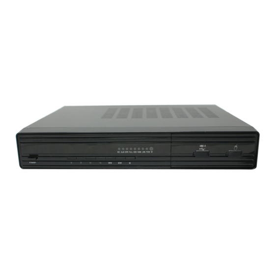
Page 50: Dvr Installation Guideline
4 DVR Installation Guideline 4.1 Product Overview 1. Product Photo 2. The Definition of Bottons and Connectors on Front Panel... - Page 51 Buttons on Front Panel Button Name Description # # # # Power STANDBY POWER/OFF, boot up DVR or shutdown DVR Navigation During the setting for GUI, use these bottons for choosing differents items on menu. And also control the direction of PTZ. ENTER Confirm Control Keys...
- Page 52 M-8304-GUI-09-A-P Item Physical Connector description connector POWER DC 19V/3A input 2 4.1.1.8 Video Two video output for connecting TV or monitor output (BNC) Video For connectiong analog video signal input (BNC) input Audio For connecting aidio signal Input Alarm I/O alarm input, 4 for 4CH DVR and 8 for 8CH DVR...
- Page 53 M-8304-GUI-09-A-P Alarm Input and Output . There are 8 sets alarm input connector and 1 set output for this DVR. Alarm input is for connection IR annunciator, fog sensor. The connection diagram of DC alarm inout as following: Connection diagram of AC alarm input as following:...
- Page 54 M-8304-GUI-09-A-P The connection diagram of alarm output as following: 220V 6. System Network Diagram...
-
Page 55: Hdd Installation
M-8304-GUI-09-A-P 4.2 HDD Installation Please installation the HDD as the following steps: U ninstall the DVR and then you will see one HDD plate as following. )... - Page 56 M-8304-GUI-09-A-P T ake out the anti-vibration mat and screws from the accessories box ) ) Take off the HDD plate and then install the anti-vibration mat on the plate and then screw on it. I nstall the HDD on HDD plate as the following photo indicate and then screws around.
- Page 57 M-8304-GUI-09-A-P ) F ix the HDD plate on the DVR device and then cover the DVR and screw. Remark: Please format the new HDD before record.
Need help?
Do you have a question about the 8304 and is the answer not in the manual?
Questions and answers