Table of Contents
Advertisement
IGBT D
R
IMMER
ACKS
I
NSTALLATION AND
O
M
PERATION
ANUAL
I
: R
. DO NOT DISCARD.
MPORTANT
ETAIN THESE INSTRUCTIONS FOR THE END USER
IGBT D
R
IMMER
ACKS
ILSCP24 / ILSCP48
WARNING: Before installation, disconnect power at circuit breakers or remove fuses to avoid electrical
shock or damage to the unit. It is recommended that an electrician perform this installation.
For technical/sales assistance, call: 1-800-526-2731
Made in U.S.A.
P/N 85-5548
Advertisement
Table of Contents

Summary of Contents for IGBT ILSCP24
- Page 1 IGBT D IMMER ACKS ILSCP24 / ILSCP48 WARNING: Before installation, disconnect power at circuit breakers or remove fuses to avoid electrical shock or damage to the unit. It is recommended that an electrician perform this installation. For technical/sales assistance, call: 1-800-526-2731 Made in U.S.A.
-
Page 2: Table Of Contents
Installation IGBT D IMMER ACKS & Operation IMPORTANT SAFEGUARDS When using electrical equipment, basic safety precautions should always be followed including the following: a) READ A D FOLLOW ALL SAFETY I STRUCTIO S. b) Do not use outdoors. c) Do not mount near gas or electric heaters. - Page 3 Capio Plus IGBT Dimmer Rack (ILSCP24 / ILSCP48) ....... . .
-
Page 4: Installation Overview
Please read all instructions before installing this product. The Capio Plus IGBT Dimmer Racks are shipped from the factory ready to install. The door, dimmer modules and the Rack Control Module(s) may be shipped separately. The following steps are required to successfully install a Capio Plus IGBT Dimmer Rack: Review this document completely Familiarize yourself with the installation procedure before you start. -
Page 5: Mechanical Considerations
Government Printing Office, Washington, DC 20402, stock no. 004-000-00345-4. Do not energize the Capio Plus IGBT Dimmer Rack until the wiring has been approved by a technician from Philips Lighting Controls. Contact Technical Support at +1-800-526-2731 to arrange for approval. Refer to page 53. -
Page 6: Rack Overview
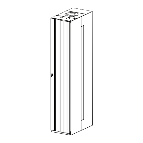
Installation IGBT D IMMER ACKS & Operation Rack Overview Figure 1: Clearances and Wiring Entry Removable panel for line/load wire entry 18" above rack 14.25" (36.20 cm) 25.75" (65.41 cm) 2" to right of rightmost rack Air filter channel Knockouts for control wire entry 82.0"... -
Page 7: Components
Installation IGBT D IMMER ACKS & Operation Components IMMER Figure 2: Dimmer Rack Components Exhaust fan Removable wiring cover Rack Control Module (RCM) upper back plane Dimmer lower back plane Phase A feed lug Dimmer module power/data connectors Load terminal blocks... -
Page 8: Rack Control Module (Rcm)
Figure 3: Rack Control Module (ILSCPRCM) Data connector Power connector Ethernet port Diagnostic port Menu display Menu controls IMMER ODULES Figure 4: 15A and 20A IGBT Dimmer Modules (CP15HP, CP20HP) Heat sink Power/data connector Test (focus) buttons and status indicators Circuit breakers with interlocking latch... - Page 9 Installation IGBT D IMMER ACKS & Operation Components (continued) Figure 5: Single 50A IGBT Dimmer Module (CP50) Heat sink ote: Maximum of 10 per ILSCR48 or 5 per ILSCR24) Power/data connector Test (focus) buttons and status indicators Circuit breaker with interlocking latch...
- Page 10 Installation IGBT D IMMER ACKS & Operation Components (continued) Figure 7: 15A and 20A Non-Dim Module (CP15ND, CP20ND) Heat Sink Power/data connector Test (focus) button and status indicators Circuit breaker with interlocking latch Figure 8: SINGLE 20A PowerSpec® HDF Fluorescent Dimmer Module (CP20HDF) * Heat Sink ote: One slot per HDF lighting circuit.
-
Page 11: Power Supply
Installation IGBT D IMMER ACKS & Operation Components (continued) OWER UPPLY Figure 9: Lytemode® Power Supply Module (ILSLMPSC) * ote: Installed in lower slot under ILSCPRCM of upper back plane. Power connector Data connector LED Status Indicator For use with Lightolier Controls® Lytemode® Architectural Lighting Control products. -
Page 12: Mounting The Rack
& Operation Warning! Capio Plus IGBT Dimmer Racks utilize dangerous voltages. Installation should be performed by trained per- sonnel only. To prevent electrical shock, turn off power at fuse box before proceeding. : This product is intended for installation in accordance with the National Electrical Code® and local or Federal code specifications. -
Page 13: Mounting Several Racks Together
Installation IGBT D IMMER ACKS & Operation Mounting the Rack (continued) OUNTING EVERAL ACKS OGETHER Figure 12: Side Knockout Placement If racks will be bused, please see "Busing Racks" on page 17 before mounting. Bolt-through knockouts Racks may be bolted together. -
Page 14: Mounting Using Vibration Isolation Fittings (Optional)
Installation IGBT D IMMER ACKS & Operation Mounting the Rack (continued) OUNTING SING IBRATION SOLATION ITTINGS OPTIONAL If racks will be bused, please see "Busing Racks" on page 17 before mount- ing. Vibration isolation fittings are available for floor mounting (Lightolier Figure 13: Attaching To Isolation Fittings Controls®... -
Page 15: Securing Rack To The Wall With Vibration Isolation Pads (Optional)
Installation IGBT D IMMER ACKS & Operation Mounting the Rack (continued) ECURING ACK TO THE ALL WITH IBRATION SOLATION OPTIONAL Vibration isolation fittings are available for wall mounting Figure 15: Attaching to Wall Using Isolation Pads (Lightolier Controls part numbers CPPAD24 or CPPAD48). -
Page 16: Line Power Wiring
RDER The Capio Plus IGBT Dimmer Rack is designed to be wired from the front. For this reason it makes sense to complete the connec- tions at the back of the rack first, and the ones at the front last. We recommend connecting the Line Power wiring and Grounds (if applicable) first, and the Load Neutral and Load Hot wires last. - Page 17 Installation IGBT D IMMER ACKS & Operation Line Power Wiring (continued) CAUTIO : Failure to use proper torque when tightening set screws will cause premature failure of the equipment! CAUTIO : Refer to local and/or National Electrical Code® for cable specifications. Failure to use the proper cable can result in damage to the equipment or danger to persons.
-
Page 18: Busing Racks
Busing Racks Capio Plus IGBT Dimmer Racks may be bused together using the optional busing kit. To bus racks, you will need to remove the pan- els as described below before the racks are bolted together or secured to a wall. - Page 19 Installation IGBT D IMMER ACKS & Operation Busing Racks (continued) ote: In the examples below, the mains feed is shown connected to the left rack, with the right rack’s lugs removed. Your application may be different, but the principle is the same.
-
Page 20: Load Wiring
Installation IGBT D IMMER ACKS & Operation Load Wiring To connect load wiring: 1. Run load wiring to the top or bottom of the rack. If your rack has the optional Ground Bus, separate the load ground wires and route them to this bus. - Page 21 Installation IGBT D IMMER ACKS & Operation Load Wiring (continued) CAUTIO : Failure to use proper torque when tightening set screws will cause premature failure of the equipment! CAUTIO : Refer to local and/or National Electrical Code® for cable specifications. Failure to use the proper cable can result in damage to the equipment or danger to persons.
-
Page 22: Control Wiring
Installation IGBT D IMMER ACKS & Operation Control Wiring DMX512 C NSTALLING ONTROL IRING INGLE 1. Run the DMX512 control wiring to the rack. Bring the conduit into the rack through the top conduit holes as shown in Figure 20. - Page 23 & Operation Control Wiring (continued) : Many manufacturers are now using Category 5 wiring for DMX512. With the Capio Plus IGBT Dimmer Rack, DMX512 must NEVER be connected using RJ-45 connectors. These connectors are for Ethernet connections only. : Control wires may also enter through side knockouts. See Figure 12 for knockout placement.
-
Page 24: Finish And Test
Call Philips Lighting Controls for Approval Do not energize the Capio Plus IGBT Dimmer Rack until the wiring has been approved by a technician from Philips Lighting Controls. Contact Technical Support at +1-866-526-2731 to arrange for approval. Refer to page 53. -
Page 25: Attaching The Door
Installation IGBT D IMMER ACKS & Operation Finish and Test (continued) TTACHING THE When all wiring and testing is complete, attach the rack door. Do not operate the rack without the door in place. 1. Remove the two screws from the bottom of the rack (Figure 21). -
Page 26: Installing Dimmer And Control Modules
Installing Dimmer and Control Modules Do not energize the Capio Plus IGBT Dimmer Rack until the wiring has been approved by a technician from Philips Lighting Controls. Contact Technical Support at +1-866-526-2731 to arrange for approval. Refer to page 53. -
Page 27: Installing The Rack Control Module (Ilscprcm)
Installation IGBT D IMMER ACKS & Operation Installing Dimmer and Control Modules (continued) NSTALLING THE ONTROL ODULE (ILSCPRCM) Figure 23: RCM Insertion 1. Insert ILSCPRCM into slot ( Figure 23 ). 2. Push the ILSCPRCM until alignment pins at back seat firmly into connector and module is seated firmly against metal frame of rack. -
Page 28: Configuration Using Rcm Lcd Menu
VERVIEW Capio Plus IGBT Dimmer Racks can be configured directly at the RCM using the built-in LCD Menu. Please note that while the built-in menu will display all system status information, it has limited configuration capabilities. Only Guardian™ software provides an interface for configuring all IGBT Dimmer Rack options. -
Page 29: Menu System
Installation IGBT D IMMER ACKS & Operation Configuration Using RCM LCD Menu (continued) YSTEM The RCM menu system consists of eight main Figure 12: Menu System Structure categories as shown in Figure 12. Menu Configuration Dimmer Inputs Config System Status... -
Page 30: Guardian Overview
& Operation Guardian™ Overview Capio Plus IGBT Dimmer Racks can be configured using a Windows compatible personal computer running Guardian software. Only the Guardian method provides an interface for configuring all system options. Guardian software is available in two versions: Guardian SE (Setup Edition) Guardian SE is used to configure Capio Plus Systems. -
Page 31: Connecting A Pc To The Capio Plus System
Installation IGBT D IMMER ACKS & Operation Connecting a PC to the Capio Plus® System A Pathport system is a data manager that utilizes a distributed network of devices that are capable of adding data to, or reading data from the network. Because the system is distributed, every device has access to all of the information being carried on the system, and can be configured to use the data differently than any other device on the system. -
Page 32: Configuring Rcm Using Guardian
ETUP Once installed on a PC, Guardian SE or NT will automatically discover and display a list of all Capio Plus IGBT Dimmer Racks connected to the network on the left of its display. Once all the units have been discovered, it is possible to Save the configuration. This will make it possible for Guardian SE or NT to detect a unit that is not responding in the future. -
Page 33: Dimmer Setup
Installation IGBT D IMMER ACKS & Operation Configuring RCM Using Guardian (continued) Power-Up Preset On power-up select preset - Select one of the eight available Local Presets to come on automatically when the system is turned on. This is extremely useful during construction when the control console in normally not available. - Page 34 800 us -- Lamp noise will be reduced 500 us -- Efficiency will be greater ote: IGBT dimmers are always silent. Standard response time Set dimmers to match the response time of other dimmers in the system. (Minimum is recommended.) Dimmer Curve Select a curve for each dimmer.
-
Page 35: Dimmer Inputs
Installation IGBT D IMMER ACKS & Operation Configuring RCM Using Guardian (continued) IMMER NPUTS Changes to the Dimmer Inputs can only be made while in the Administrative Mode. Refer to "Administrative Mode" on page 40. Select the required RCM from the RCM list at left and use the Dimmer Inputs tab to configure. - Page 36 Installation IGBT D IMMER ACKS & Operation Configuring RCM Using Guardian (continued) Properties With one or more dimmers selected, Right click and select Properties or select Properties from the Tool Bar. Mark any field <no change> to the leave data as is.
-
Page 37: Parked Dimmers
Installation IGBT D IMMER ACKS & Operation Configuring RCM Using Guardian (continued) ARKED IMMERS Changes to the Parked Dimmers can only be made while in the Administrative Mode. Refer to "Administrative Mode" on page 40. Select the required RCM from the RCM list at left and use the Parked Dimmers tab to configure. -
Page 38: Local Presets
Installation IGBT D IMMER ACKS & Operation Configuring RCM Using Guardian (continued) OCAL RESETS Changes to the Local Presets can only be made while in the Administrative Mode. Refer to "Administrative Mode" on page 40. Select the required RCM from the RCM list at left and use the Local Presets tab to configure. -
Page 39: Save Rcm Configuration
Installation IGBT D IMMER ACKS & Operation Configuring RCM Using Guardian (continued) Sorting RCM List The RCM list in the left hand column can be sorted to make viewing more convenient. Right click in the column to sort. RCM C ONFIGURATION The configuration of any Capio Plus System can be saved to an RCM Data file (*.rcm2). -
Page 40: Basic Guardian Operations
Installation IGBT D IMMER ACKS & Operation Basic Guardian Operations Once you have installed Guardian software on a PC and connected it to the Capio Plus System(s) via the network, you may set up options and configure individual dimmers. ISCOVERY Guardian SE or NT will automatically discover and display a list of all Capio Plus Systems connected to the network. -
Page 41: Saving Files
Installation IGBT D IMMER ACKS & Operation Basic Guardian Operations (continued) AVING ILES The Save function will save a Dimmer Network file. This file stores the following information: • List of connected Capio Plus Systems. • Which Capio Plus Systems or Dimmers should be ignored. -
Page 42: Dimmer Load Snapshot (Guardian Nt Only)
IGBT D Installation IMMER ACKS & Operation Basic Guardian Operations (continued) NT O IMMER NAPSHOT UARDIAN • The Snapshot function, available with Guardian NT (sold separately*), is used to sample the load of all dimmers in the system and remember the load for future comparison. -
Page 43: Guardian Setup
Installation IGBT D IMMER ACKS & Operation Guardian Setup ERIAL ATHPORT ONLY In the absence of a Pathport Enabled network, Guardian can configure and get status from a single Capio Plus System connected to a serial port. In this case, the RCM will need to be setup for direct serial connection. -
Page 44: Report Logging (Guardian Nt Only)
Installation IGBT D IMMER ACKS & Operation Guardian Setup (continued) NT O EPORT OGGING UARDIAN Guardian NT (sold separately*) has the ability to keep a log of all detected errors. To set Log Options: 1. Select Email / Log File from the Setup menu. -
Page 45: Dimmer Status (Guardian Nt Only)
Installation IGBT D IMMER ACKS & Operation Guardian Setup (continued) 2. Send a test email using the new settings. 3. Select Email / Log File from the Setup menu. 4. Select Email Errors Immediately if you wish to have email sent when the error is detected. - Page 46 Dimmer has detected an overload (excessive current) due to a short circuit or a load that exceeds the dimmer’s rating. igbt An IGBT has failed. The read-only memory checksum is incorrect. analog Either the voltage or the current-sensing electronics has failed.
-
Page 47: Troubleshooting
Installation IGBT D IMMER ACKS & Operation Troubleshooting A PC running the Guardian Configuration Utility can tell you many things about the system. Troubleshoot using the Guardian Configuration Utility: Connect the PC to the Capio Plus System as described on page 16. Use the directions in "Basic Guardian Operations" on page 25, to access the Capio Plus System configuration. -
Page 48: Checklist
(Complete the "ENGINEERING CHECK-OUT REQUEST FORM" at the end of this manual.) Do not energize the Capio Plus IGBT Dimmer Rack until the wiring has been approved by a technician from Philips Lighting Controls. Contact Technical Support at +1-866-526-2731 to arrange for approval. Refer to page 53. -
Page 49: Appendix A: Standard Wiring
Installation IGBT D IMMER ACKS & Operation Appendix A: Standard Wiring DMX512 ILS Terminal XLR Pin WE Color Code IECA Color Belden Std. CATEGORY 5 Name Name (e.g. Belden #8132) Code Color Code Color Code Drain Drain Brown (8) Drain (Shield) -
Page 50: Termination Of Shielded Cable
Installation IGBT D IMMER ACKS & Operation Appendix A: Standard Wiring (continued) ERMINATION OF HIELDED ABLE To terminate shielded cable: Maximum for Maximum for XLR Dimension Name Minimum 1. Strip off specified length of outer jacket. Terminal (In-Line) 2. Cut shield (foil or braid) flush to outer Remove Cable Jacket 1"... -
Page 51: Appendix B: Specifications
82 inches high (46 for ILSCP48) x 14.25 inches wide* x 26.938 inches deep (with door) (208.28 cm H x 36.20 cm W x 68.42 cm D) 200 pounds empty (90.72 kg) / (ILSCP24 125 pounds empty) * Right-most rack requires an additional 2" clearance for proper door operation. -
Page 52: Capio Plus Rack Control Module (Ilscprcm)
IMMER ODULES CP20HP: Capio Plus High Performance Dual 20A IGBT Dimmer Module (800 us) 2.75 pounds ( 1.247 kg) CP15HP: Capio Plus High Performance Dual 15A IGBT Dimmer Module (800 us) 2.75 pounds ( 1.247 kg) CP50: Capio Plus High Performance Single 50A IGBT Dimmer Module (800 us) 2.75 pounds ( 1.247 kg) CP20ND: Capio Plus High Performance Dual 20A Non-Dim Module 2.75 pounds ( 1.247 kg) -
Page 53: Notice To Contractor
Installation IGBT D IMMER ACKS & Operation OTICE ONTRACTOR DO OT No part of this system may be energized or operated until the installation has been approved by a Philips Controls Representative. Violation of this Requirement may damage components and therefore constitute misuse under standard warranty terms. Such misuse may relieve Genlyte Controls of any and all further obligations under the terms of this warranty. -
Page 54: Engineering Check-Out Request Form
Installation IGBT D IMMER ACKS & Operation NGINEERING HECK EQUEST Please review the on the previous page. Upon completion of the requirements outlined in the Notice, make a copy of this form, complete all information and fax it to Genlyte Controls Technical Services (fax: +1-972-389-6175). - Page 55 Installation IGBT D IMMER ACKS & Operation Notes 3 YEAR LIMITED WARRANTY Philips Controls warrants that this product will be free from defects in workmanship or materials. This warranty is void on any electronic controls which have been overloaded, abused, improperly installed or altered in any manner.
Need help?
Do you have a question about the ILSCP24 and is the answer not in the manual?
Questions and answers