
Summary of Contents for murco MGS
- Page 1 Gas Detector Installation and Operation Manual Instruction 1000-0085 Revision 0 – July 2013 Product Leadership • Training • Service • Reliability...
- Page 2 BATTERIES HAVE INDIVIDUAL WARRANTIES). SHOULD YOUR INSTRUMENT REQUIRE NON-WARRANTY REPAIR, YOU MAY CONTACT THE DISTRIBUTOR FROM WHOM IT WAS PURCHASED OR YOU MAY CONTACT MURCO DIRECTLY. IF MURCO IS TO DO THE REPAIR WORK, SEND THE INSTRUMENT, PREPAID, TO MURCO AT THE FOLLOWING ADDRESS. MURCO...
- Page 3 COPYRIGHT PROTECTION. ALL RIGHTS ARE RESERVED. NO PARTY MAY USE OR COPY SUCH SOFTWARE IN ANY MANNER OR FORMAT, EXCEPT TO THE EXTENT THAT MURCO GRANTS THEM A LICENSE TO DO SO. IF THIS SOFTWARE IS BEING LOADED ONTO MORE THAN ONE COMPUTER, EXTRA SOFTWARE LICENSES MUST BE PURCHASED.
-
Page 4: Table Of Contents
MGS Installation and Operation Manual Table of Contents Section 1. Overview ..................5 1.1. General Information .................. 5 1.2. Technical Specifications ................6 Section 2. Installation and Wiring ..............8 2.1. General Placement Guidelines ..............9 2.2. Components and Access Overview ............9 2.3. -
Page 5: Section 1. Overview
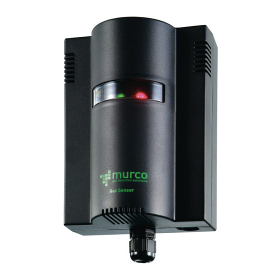
Overview 1.1. General Information The MGS is a state-of-the-art fixed gas detector which can detect a wide range of different gases. The gas sensors can be used on a stand-alone basis or integrated into Controls or Building Management Systems (BMS). -
Page 6: Technical Specifications
MGS Installation and Operation Manual 1.2. Technical Specifications Specification Description Power Supply 12-24 VDC, 12-24 VAC 50/60 Hz, 2 W max. Power consumption (12V): 60mA (EC), 153mA (SC), 136mA (IR) Power Monitoring Green LED Visual Alarm Red LED Audible Alarm... - Page 7 MGS Installation and Operation Manual Supported CFM/Duct Sizes for the Duct Mount Housing Units Duct Size Inches 12 x 12 12 x 24 18 x 18 24 x 24 24 round Feet 1 x 1 1 x 2 1.5 x 1.5...
-
Page 8: Section 2. Installation And Wiring
MGS Installation and Operation Manual Section 2. Installation and Wiring WARNING: Explosion hazard! Do not mount the MGS in an area that may contain flammable liquids, vapors, or aerosols. Operation of any electrical equipment in such an environment constitutes a safety hazard. -
Page 9: General Placement Guidelines
MGS Installation and Operation Manual 2.1. General Placement Guidelines NOTE: The MGS should be installed plumb and level and securely fastened to a rigid mounting surface. Sensors must be located within the appropriate wire lengths from the central control unit (if used). - Page 10 MGS Installation and Operation Manual Figure 2. EC or IR Sensor Components and Wiring 1000-0085 Rev 0...
- Page 11 MGS Installation and Operation Manual Figure 3. SC Sensor Components and Wiring 1000-0085 Rev 0...
-
Page 12: Machinery Rooms
MGS Installation and Operation Manual Item Description Enclosure To open the standard sensor enclosure (IP41 model), turn Access the cable clamp 1/2 turn counter-clockwise to loosen the internal gland nut, depress the clip on top of the enclosure and open. Reverse to close. (Note: For the IP66 enclosure, use the four bolts on the front cover.) - Page 13 MGS Installation and Operation Manual plant room would be around compressors, pressurised storage vessels, refrigerant cylinders or storage rooms or pipelines. The most common leak sources are valves, gauges, flanges, joints (brazed or mechanical), filling or draining connections, etc. When mechanical or natural ventilation is present, mount a sensor •...
-
Page 14: Refrigerated Spaces
MGS Installation and Operation Manual 2.4. Refrigerated Spaces In refrigerated spaces, sensors should be located in the return airflow to the evaporators on a sidewall (below head-high is preferred), or on the ceiling, not directly in front of an evaporator. In large rooms with multiple evaporators, sensors should be mounted on the central line between 2 adjacent evaporators, as turbulence will result in airflows mixing. -
Page 15: Air Conditioning (Direct Systems Vrf/Vrv)
MGS Installation and Operation Manual 2.6. Air Conditioning (Direct Systems VRF/VRV) For compliance with EN378, at least one detector shall be installed in each occupied space being considered and the location of detectors shall be chosen in relation to the refrigerant and they shall be located where the refrigerant from the leak will collect. -
Page 16: Section 3. Housing Dimensions
MGS Installation and Operation Manual Section 3. Housing Dimensions Figure 4. MGS Standard Housing 1000-0085 Rev 0... - Page 17 MGS Installation and Operation Manual Figure 5. IP66 Housing with Splashguard 1000-0085 Rev 0...
- Page 18 MGS Installation and Operation Manual Figure 6. IP66Airflow Duct Mount Housing Units = mm Figure 7. Exd Housing 1000-0085 Rev 0...
- Page 19 MGS Installation and Operation Manual 9.8 feet (3 meters) Typical For Dimensions and Mounting Locations , See Figure 5. Figure 8. IP66 Housing with Remote Sensor Head NOTE: For the Exd Remote Sensor Head and 16.4 ft (5 m) cable, the thread varies based on the model.
-
Page 20: Section 4. Operation And Stabilisation
MGS Installation and Operation Manual Section 4. Operation and Stabilisation On powering up, the MGS will sense for the presence of gas after an initial warm-up delay of 5 minutes. The green LED will flash at 1 second intervals during the warm-up. -
Page 21: Section 5. Configurations
MGS Installation and Operation Manual Section 5. Configurations 5.1. Overview Function Description Time Delay Available on the audible alarm and relay to avoid false alarms. This is set with jumpers. The default delay is 0 minutes. You may wish to set to 15 minutes during start up. -
Page 22: Section 6. Functional Tests And Calibration
IMPORTANT: If the MGS is exposed to a large leak it should be tested to ensure correct functionality by electrically resetting the zero setting and carrying out a bump test. See procedures below. IMPORTANT: Murco recommends annual checks and gas calibration. - Page 23 IMPORTANT: Before testing the sensors on-site, the MGS must have been powered up and allowed to stabilise. IMPORTANT: The testing and/or calibration of the unit must be carried out by a suitably qualified technician, and must be done: •...
-
Page 24: Bump Testing
CAUTION: Before you carry out the test or calibration: • Advise occupants, plant operators, and supervisors. • Check if the MGS is connected to external systems such as sprinkler systems, plant shut down, external sirens and beacons, ventilation, etc. and disconnect as instructed by the customer. - Page 25 0V and VS. Expose the sensor to gas from the cylinder. You can place the entire MGS into a plastic bag or use a plastic hose/hood to direct gas to the sensor head. A response of above 80% is acceptable.
- Page 26 MGS Installation and Operation Manual Figure 9. Gas Cylinder and Test Hardware Gas ampoules are convenient and inexpensive alternatives to using gas cylinders for bump testing. Step Bump Testing Using Gas Ampoules Make sure that both the ampoules and the calibration beaker are clean and dry.
-
Page 27: Calibration Overview
VS using a 0-5V scale. If the sensor range is 0-1000 ppm, then 5V=1000 ppm. Murco offers a calibration kit that consists of a calibration gas cylinder, a flow regulation valve with flexible non-absorbent tubing and vented calibration hood. Tools required:... -
Page 28: Calculating Calibration Voltage
MGS Installation and Operation Manual • Gas cylinder with the appropriate gas and concentration • A voltmeter (crocodile clips recommended) • Screwdriver (depending on housing). three sensor versions: semiconductor (SC), electrochemical (EC), and infrared (IR). 6.4. Calculating Calibration Voltage Sensor outputs are linear. As long as you have a gas cylinder of known concentration you can calibrate to any desired range. -
Page 29: Calibrating Electrochemical (Ec) Sensors
MGS Installation and Operation Manual 6.6. Calibrating Electrochemical (EC) Sensors There are two adjustments required: zero and span. They are monitored at 0V and VS using a 0-5V scale. If the sensor range is 0-1000 ppm, then 5V=1000 ppm. Step Calibrating Electrochemical (EC) Sensors Locate Pot VR201 which is used to adjust the zero point. -
Page 30: Section 7. Troubleshooting
Possible Cause(s) • Check power supply. Check wiring. Green and Red light • MGS was possibly damaged in transit. Check by installing another MGS to confirm the fault. • Sensor may be disconnected from printed Red light on, green led circuit board. -
Page 31: Ce Declaration Of Conformity
Compatibility (EMC) Measurement of Combustible Gases, Toxic Standards Gases, or Oxygen Signature: Name: Philip Hassell Title: Engineer Manager Date: March 2013 The technical documentation file required by this directive is maintained at the corporate headquarters of Murco Ltd. 1000-0085 Rev 0... - Page 32 MGS Installation and Operation Manual MURCO 114A GEORGES STREET LOWER DUN LAOGHAIRE • CO DUBLIN • IRELAND www.murcogasdetection.com Phone: +353 1 284 6388 • Fax: +353 1 284 6389 • sales@murco.ie 1000-0085 Rev 0...
Need help?
Do you have a question about the MGS and is the answer not in the manual?
Questions and answers