Table of Contents
Advertisement
Advertisement
Table of Contents
Troubleshooting

Summary of Contents for Majorpower Corporation Majorsine
- Page 1 Majorsine Power Inverter INSTALLATION & OPERATION MANUAL...
-
Page 2: Revision History
March 2008 Issue 4 Copyright Notice ©2008, Majorpower Corporation. All rights reserved. This document may not be copied in whole or in part, or transferred to any other media, without the written permission of Majorpower Corporation. Printed in the United States of America. - Page 3 MAJORSINE Inverter Manual / M101.4 Notes: Model Number: Serial Number: Installation Date: This user’s manual contains important technical instructions to be followed by qualified personnel responsible for the installation, start-up and maintenance of this unit. It is recommended that this manual be read attentively to insure safe and reliable operation of this equipment.
- Page 4 MAJORSINE Inverter Manual / M101.4 Warranty Majorpower Corporation Warranty Summary for MAJORSINE A standard 2 year manufacturer warranty is in effect for the products in our MAJORSINE Power Inverter family. The standard warranty includes depot repair or replacement of any unit that fails during the first two years in operation due to a defect in materials or workmanship.
-
Page 5: Table Of Contents
MAJORSINE Inverter Manual / M101.4 Table of Contents 1. INTRODUCTION.............. 7 1-1 G ...............7 ENERAL NFORMATION 2. IMPORTANT SAFETY INSTRUCTIONS....8 2-1 S ..............8 AFETY TATEMENT 2-2 A ............8 DDITIONAL AFETY OTES 2-3 S ..................9 YMBOLS 3. PRODUCT OVERVIEW ..........10 3-1 S ..............10... - Page 6 MAJORSINE Inverter Manual / M101.4 7-2 SNMP E (WEB)........30 XPANSION 7-3 RS-232 C (GUI)........31 OMMUNICATION 8. TECHNICAL SPECIFICATIONS......... 32 MAJORSINE1000-24-2U ..............32 MAJORSINE1000-48-2U ..............33 MAJORSINE2000-48-2U ..............34 MAJORSINE1000-125-2U ..............35 MAJORSINE2000-125-2U ..............36 MAJORSINE1000 -48-2U...............37 MAJORSINE2000 -48-2U...............38 . MPXXXNX02ABX..........39 RAWING 9. OPTIONAL HARDWARE:..........40...
-
Page 7: Introduction
These intelligent, dependable inverters provide economical AC Power for all your network needs. Operators spanning global continents have deployed the MAJORSINE as the choice for high availability AC power support from a DC source. This manual contains information and technical details for all models in the MAJORSINE Power Inverter family. -
Page 8: Important Safety Instructions
SAVE THESE INSTRUCTIONS - This manual contains important inverter instructions that should be followed during installation and maintenance of the MAJORSINE inverter unit. To reduce the risk of electric shock, install the inverter in a temperature and humidity controlled indoor environment, free of conductive contaminants. -
Page 9: Symbols
MAJORSINE Inverter Manual / M101.4 Reduced air flow: Installation of the equipment in a rack should be such that the amount of air flow required for safe operation of the equipment is not compromised. Mechanical loading: Mounting of the inverter in a rack should be level and balanced. -
Page 10: Product Overview
MAJORSINE Inverter Manual / M101.4 3. PRODUCT OVERVIEW 3-1 System Features The MAJORSINE series inverter is a highly reliable DC-AC inverter system, designed with advanced power electronics and microprocessor technology offering the following features: Self-Diagnosis The MAJORSINE series inverter is equipped with a self diagnosis microprocessor, able to identify and show all failure messages on the LED/LCD display, with visual/audio alarm. -
Page 11: Block Diagram
FILTER OUTPUT OUTPUT RELAY BREAKER MAJORSINE inverters feature IGBT (Insulated Gate Bipolar Transistor) technology, minimizing weight and dimension, while enhancing output short circuit reliability and overload capacity. Output voltage is provided in one of two ways: 1) From AC input bypass mode: (Off-Line Mode) 2) From DC to AC inverter mode: (On-Line Mode) Either mode is front panel programmable;... -
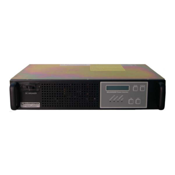
Page 12: Front Panel
MAJORSINE Inverter Manual / M101.4 3-3 Front Panel MAJORPOWER.COM Tel: 514.369.4919 Fax: 514.369.4817 http://www.majorpower.com ON/OFF buttons: These are the two power buttons for turning on or turning off the inverter. Once the inverter is on, the “ON” button works as the On-Line <=>... -
Page 13: Rear Panel
DC breaker. 3-4 Rear Panel Communication Interface MAJORSINE Inverter provides two standard and integrated communication interfaces a) RS-232 interface. b) Dry Contact interface. -
Page 14: Bypass Switching And Grounding
MAJORSINE Inverter Manual / M101.4 AC Input Terminal Terminal for bypass VAC input voltage. AC Input Breaker Breaker for AC input DC Input Terminal Terminal for VDC input voltage. FLOATING input “+” and “-”connection. Dry Contact Terminal Dry contact terminal is connected to two Form C relays. -
Page 15: Installation
MAJORSINE Inverter Manual / M101.4 Grounding: Chassis to Earth Ground connection should be made per customer installation specifications prevailing safety jurisdiction authority. The inverter external safety ground plane is not switched by operation in any mode. Typically - the chassis is mounted in a rack or a conductor to ground plane is installed. -
Page 16: Installation Tool Kit
MAJORSINE Inverter Manual / M101.4 Use the following recommended cable sizes when connecting power to the inverter. Model Capacity DC Input AC Input AC Output MAJORSINE1000-24-2U 1 KVA #6 AWG #14 AWG NEMA 5-15R MAJORSINE1000-48-2U 1 KVA #10 AWG #14 AWG... -
Page 17: Operation
MAJORSINE Inverter Manual / M101.4 5. OPERATION 5-1 Connecting the Input Power Once the DC power has been connected, engage the DC breaker to operate the inverter. Turn ON the AC bypass supply. Typically a circuit breaker in the service panel. -
Page 18: Front Panel Operation (Firmware Version 0.0 Or 3.1)
MAJORSINE Inverter Manual / M101.4 5-3 Front Panel Operation (Firmware Version 0.0 or 3.1) 1. Make sure that the complete installation has been carried out correctly. When the breaker is turned on or the utility input is available, the LCD of the inverter will display either... -
Page 19: A Front Panel Operation - Settings @ Start -U P
MAJORSINE Inverter Manual / M101.4 5-3a Front Panel Operation – Settings @ Start-Up The INVERTER will automatically initiate self-checks and start-up after 10 seconds. Press ON Button at least 1 full sec. SET F=60 V= 115 I/P F=60 V= 118... -
Page 20: Data" Button
MAJORSINE Inverter Manual / M101.4 5-4 “DATA” button You can use the "DATA" button to select the following information which is displayed on the LCD screen: A) Output voltage: Shows present output voltage. OUTPUT VOLT. . V *** B) Inverter voltage: Shows present “inverter”... - Page 21 MAJORSINE Inverter Manual / M101.4 F) Input DC voltage: Shows the input DC voltage. INPUT DC VOLTAGE . V *** G) Output current: Shows present output current. OUTPUT CURRENT . A *** H) Output VA: Shows present output Volt-Amp OUTPUT VA...
-
Page 22: Status" Button
MAJORSINE Inverter Manual / M101.4 5-5 “STATUS” button You can use the "STATUS" button to select the following information which is displayed on the LCD screen: A) Output status: a) When the input bypass voltage is normal and INVERTER output voltage is from DC to AC inverter,... - Page 23 MAJORSINE Inverter Manual / M101.4 b) When the inverter is over temperature (may be caused by overload, high ambient temperature or fan failure), LCD shows. ** INVERTER ** OVER TEMPERATURE c) When the temperature inside the INVERTER is too high, LCD shows.
- Page 24 MAJORSINE Inverter Manual / M101.4 h) When the INVERTER voltage is “low”, LCD shows. ** INVERTER ** UNDER VOLTAGE C) Bypass AC status a) When the input bypass voltage is normal, LCD shows. ** BYPASS AC ** NORMAL b) When the input bypass voltage is normal and INVERTER output is in “bypass mode”, LCD shows...
- Page 25 MAJORSINE Inverter Manual / M101.4 e) When the input bypass is “over” normal frequency range, LCD shows. ** BYPASS AC ** OUT OF FREQ. f) When the output is overloaded, LCD shows. ** BYPASS AC ** OVER LOAD D) Input DC status a) When the input DC voltage is normal.
-
Page 26: Error Message
MAJORSINE Inverter Manual / M101.4 e) When the input DC voltage is over voltage, INVERTER will switch to bypass mode (if bypass AC is available) and LCD shows. DC OVER VOLT INVERTER OFF 5-6 Error message If the following messages appear on the LCD screen, contact Majorpower at once. -
Page 27: Troubleshooting
MAJORSINE Inverter Manual / M101.4 6-2 Troubleshooting Problem Possible cause Action to take Turn on or reset the The circuit breaker is “off” circuit breaker. DC cable polarity Apply correct DC LEDs do not light up installation polarity. DC input is “over” or Apply correct DC “under”... -
Page 28: Alarms
MAJORSINE Inverter Manual / M101.4 6-3 Alarms Inverter Alarm Classifications Fault Alarm Indicator includes: Bypass AC Input High or Low Voltage Bypass AC Input Frequency Out of Range Fan Fail Inverter Internal Failure Output Load Sensing “short” condition High Temperature... - Page 29 MAJORSINE Inverter Manual / M101.4 Bypass Utility AC Alarm Thresholds For 100VAC system O/P = 100Vac O/P = 110Vac O/P = 115Vac O/P = 120Vac AC Bypass Voltage 80Vac ~ 90Vac 95Vac ~ 100Vac Range 120Vac ~130Vac 135Vac ~140Vac AC Bypass Frequency Range F=50Hz 45.5Hz ~ 54.5Hz...
-
Page 30: Communication
MAJORSINE Inverter Manual / M101.4 7. COMMUNICATION 7-1 Dry Contact Communication Terminal The “Dry Contact” terminal is the interface for two Form C relays. The relays are used for switching the voltage provided by the user’s external alarm system. One contact set is for “DC Abnormal” and the other one is for “FAULT”. -
Page 31: Rs-232 Communication Port (Gui)
MAJORSINE Inverter Manual / M101.4 7-3 RS-232 Communication Port (GUI) The RS-232 communication port provides the following features using a GUI software package that is available by request from Majorpower Corporation: 1) Communicates Fault, DC abnormal, Overload, Inverter Fail etc. -
Page 32: Technical Specifications
MAJORSINE Inverter Manual / M101.4 8. TECHNICAL SPECIFICATIONS MAJORSINE1000-24-2U DC Input Voltage 20-30 VDC Rated Current 50 Amps Protection Fuse and DC Breaker Efficiency >85% (full linear load), 24 VDC I/P, 120 VAC O/P AC Output Capacity 1KVA / 800W... -
Page 33: Majorsine1000-48-2U
MAJORSINE Inverter Manual / M101.4 MAJORSINE1000-48-2U DC Input Voltage 40-60 VDC Rated Current 25 Amps Protection Fuse and DC Breaker Efficiency >85% (full linear load), 48 VDC I/P, 120 VAC O/P AC Output Capacity 1KVA / 800W Voltage 100, 110, 115, 120 VAC Voltage Regulation ±2%... -
Page 34: Majorsine2000-48-2U
MAJORSINE Inverter Manual / M101.4 MAJORSINE2000-48-2U DC Input Voltage 40-60 VDC Rated Current 50 Amps Protection Fuse and DC Breaker Efficiency >85% (full linear load), 48 VDC I/P, 120 VAC O/P AC Output Capacity 2KVA / 1600W Voltage 100, 110, 115, 120 VAC Voltage Regulation ±2%... -
Page 35: Majorsine1000-125-2U
MAJORSINE Inverter Manual / M101.4 MAJORSINE1000-125-2U DC Input Voltage 100-150 VDC Rated Current 10 Amps Protection Fuse and DC Breaker Efficiency >85% (full linear load), 125 VDC I/P, 120 VAC O/P AC Output Capacity 1KVA / 800W Voltage 100, 110, 115, 120 VAC Voltage Regulation ±2%... -
Page 36: Majorsine2000-125-2U
MAJORSINE Inverter Manual / M101.4 MAJORSINE2000-125-2U DC Input Voltage 100-150 VDC Rated Current 20 Amps Protection Fuse and DC Breaker Efficiency >85% (full linear load), 125 VDC I/P, 120 VAC O/P AC Output Capacity 2KVA / 1600W Voltage 100, 110, 115, 120 VAC Voltage Regulation ±2%... -
Page 37: Majorsine1000I-48-2U
MAJORSINE Inverter Manual / M101.4 MAJORSINE1000i-48-2U DC Input Voltage 40-60 VDC Rated Current 25 Amps Protection Fuse and DC Breaker Efficiency >85% (full linear load), 48 VDC I/P, 230 VAC O/P AC Output Capacity 1KVA / 800W Voltage 208, 220, 230, 240 VAC Voltage Regulation ±2%... -
Page 38: Majorsine2000I-48-2U
MAJORSINE Inverter Manual / M101.4 MAJORSINE2000i-48-2U DC Input Voltage 40-60 VDC Rated Current 50 Amps Protection Fuse and DC Breaker Efficiency >85% (full linear load), 48 VDC I/P, 230 VAC O/P AC Output Capacity 2KVA / 1600W Voltage 208, 220, 230, 240 VAC Voltage Regulation ±2%... -
Page 39: Drawing No. Mpxxxnx02Abx
MAJORSINE Inverter Manual / M101.4 Drawing No. MPXXXNX02ABX Page 39... -
Page 40: Optional Hardware
MAJORSINE Inverter Manual / M101.4 9. Optional Hardware: SNMP Remote Communication Card: Remote monitoring is a prime consideration and requirement to manage multiple network elements from a central location. Remote access is established by simply installing the plug-n-play card, configuring your network IP address, and attaching the network interface cable.
Need help?
Do you have a question about the Majorsine and is the answer not in the manual?
Questions and answers