Table of Contents
Advertisement
Advertisement
Table of Contents

Related Manuals for LA Fitness Runfit 99


Summary of Contents for LA Fitness Runfit 99
- Page 1 RUNFIT 99 OWNER’S MANUAL...
-
Page 2: Table Of Contents
Table of Contents Components Check ..............................2 Overview Drawing...............................3 Computer Console............................4 ISP Slot And C-SAFE Slot ..........................5 Wire Rod System And Power Switch......................6 Running Belt And Side Incline Base......................7 Caution..................................8 Important Safety Instructions .........................8 Electrical Power Requirement........................10 Adding SILICON ............................11 ADD SILICONE ............................12 Leveling Adjustment ............................13 Power Switch ...............................13 Centering The Belt ............................14... -
Page 3: Components Check
1 Components Check Please check the following parts carefully after opening the box. If there are any missing please contact your sales agent Parts kit Left Upright x1 Right Upright x1 Computer Console x1 Frame x1 2011/11/7 V1.1+V1.0... -
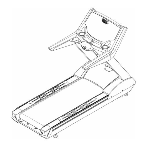
Page 4: Overview Drawing
2 Overview Drawing Fan Vent Touch sensor console Hand Pulse Set Bottle Holder Emergency Key Handrail Running Belt Anti Slip Pad Frame Adjustable Foot 2011/11/7 V1.1+V1.0... -
Page 5: Computer Console
2-1 Computer Console Adjust to change the wind direction. Touch sensor console See detailed instructions at 5-1 Computer Structure Bottle Holder Emergency Stop Refer to 3-8 Emergency Stop Utility Tray 2011/11/7 V1.1+V1.0... -
Page 6: Isp Slot And C-Safe Slot
2-2 ISP Slot And C-SAFE Slot ISP Slot In the event of an upgrade to the software is necessary, this port will be used. C-SAFE Slot This treadmill can be connected network by the RJ45 port on the back of control board. -
Page 7: Wire Rod System And Power Switch
2-3 Wire System And Power Switch Wire System Coil the extra power cord on this to tidy it up. CAUTION ! Don’t carry the treadmill by this as it will bend. Power Socket Power Switch Circuit Breaker Power Switch Circuit Breaker If the current goes over the rated value, it will reset automatically. -
Page 8: Running Belt And Side Incline Base
2-4 Running Belt And Side Incline Base Warning Running Belt Keep hands away from the running belt while the treadmill is running. If service needs to be done near this area, turn the treadmill off and unplug the unit first. Warning Side Incline Base Keep hands away from the front end of the treadmill and elevation arm. -
Page 9: Caution
3 Caution 3-1 Important Safety Instructions Warning: To reduce the risk of burn, fire, electric shock, or physical injury, please read the important safety instructions and product information carefully before starting to use this product. The owner of the treadmill should take on the responsibility to make sure that all the users can fully understand the cautions and important safety instructions •... - Page 10 • Before using the treadmill, please examine every part first. • Never drop or insert any objects into any vent of the treadmill. • Always follow the important safety instructions before connecting the treadmill to the grounded outlet. • Keep the power cord far away from incline wheels. Do not put the power cord under the treadmill and never use a damaged power cord.
-
Page 11: Electrical Power Requirement
3-2 Electrical Power Requirement This treadmill requires special power: Supply Voltage V Frequency HZ Rated Currency A 50/60 50/60 50/60 50/60 50/60 240+ 50/60 A dedicated outlet is REQUIRED for this treadmill. The hot, neutral and ground wires must each be routed independently (not looped or tied to other circuits. -
Page 12: Adding Silicon
3-3 Adding SILICON If necessary use the Hex Wrench to unscrew the bolt inside the Rear End Cap. Then pull the belt up and daub some SILICON to the center of the board. After that, adjust the belt to the center of the deck, followed by tightening the screw to the original set. -
Page 13: Add Silicone
3-4 ADD SILICONE Time of add SILICONE When suggested time of adding SILICONE is achieved, please extend your hand to the center of the running board to make sure whether there is any SILICONE before adding. If no SILICONE on the running board, please add 30cc SILICONE to the running board. -
Page 14: Leveling Adjustment
3-5 Leveling Adjustment An uneven floor may cause the treadmill to rock while it is running. Adjust the leveling feet as follows to make the unit stable. The method of adjustment is as follows: 1. Turn A counter-clockwise to loosen it. 2. -
Page 15: Centering The Belt
3-7 Centering The Belt After installing and leveling the treadmill, check the belt to ensure that it is tracking properly. First, plug the power cord into an appropriate dedicated outlet. Then, turn the treadmill ON. Have one person stand on the anti-slip pads on either side of the treadmill frame. -
Page 16: Emergency Stop System
3-8 Emergency Stop System This treadmill has a safety stop system via the emergency stop key. There are two methods that can stop the treadmill temporarily. Press the Safety Key Press the Safety key, the treadmill will stop running immediately. Pull on the safety cable Pull out the wire downwards, the treadmill will stop running... - Page 17 Warning: When you pull the cable or press the Safety key, the part which is tied with rope will protrude. Press the protruded part back, the treadmill will be back to the start/ready status. Press the protruded part back The treadmill goes back to the start/ready status 2011/11/7 V1.1+V1.0...
-
Page 18: Fitness Networking
3-9 Fitness Networking The treadmill can connect to the network by the RJ45 port on the back of control board. Figure 2011/11/7 V1.1+V1.0... -
Page 19: Assembly Instructions
4 Assembly Instructions Please read the instructions carefully before assembling the unit,then choose a flat position to start. 4-1 Pre-Assembly Check List ITEM Description Computer Console Frame Left Upright Right Upright 2011/11/7 V1.1+V1.0... - Page 20 Parts kit ITEM Description Hex Screw M10xP1.5x70 Hex Screw M8XP1.25x15 Hex Wrench 5mm x 80mm x 80mm Hex Wrench 6mm x 80mm x 80mm Hex Wrench 10mm x 65mm x120mm Bushing Wrench + Screwdriver SILICONE Hex Screw M8XP1.25x20 Washerψ8 xψ19 x 3.0 Spring Washer M8 2011/11/7 V1.1+V1.0...
-
Page 21: Assembly Steps
4-2 Assembly Steps Control Wire Extension Upper Motor Cover Philips Screw Philips Screw Running Belt Washer Spring Washer Hex Screw Philips Screw Frame Washer Spring Washer Hex Screw Philips Screw Two people should finish the assembly steps. (Caution!! Please follow exactly the assemly steps below to aviod injury.) 1. - Page 22 computer grounding wire Computer Control Wire Upright Control Wire Frame grounding wire Put the Computer Console (A) on the upper part of the Uprights(C,D) on the assembled Frame(B), and connect the uprights control wire with computer control wires. Last, tighten the computer console with Hex Screw(b) on the upper part of uprights.
-
Page 23: Computer
5 Computer With this easy-to-use computer, the treadmill allows users to tailor a workout to personal fitness abilities and goals and to monitor progress. 5-1 Computer Structure A – WORKOUT PROFILE WINDOW: During a workout, interval hills and valleys appear in this window as rows of light stacked in columns. - Page 24 C – INCLINE and SPEED ARROW keys: C1 – Increase Incline of the Treadmill Deck during Exercises Press this key to increase the incline of the treadmill deck, the upper limit is 15%, steps are 0.1%. (The incline cannot be changed in some automatic programs.) C2 –...
- Page 25 Emergency Stop Key – Press this key during your workout to immediately stop the treadmill, see section 3-7 for more information. Emergency Stop Key Manual Replacement: – Please refer to 3-7 Emergency Stop System. I – QUICK INCLINE key: Press this key during exercises, the incline display window will blink. At this time, use the NUMERIC keypad to choose the incline value, then press ENTER to confirm.
-
Page 26: Bottle Holder And Utilities Trays
5-2 Bottle Holder and Utilities Trays Computer Console includes a bottle holder(A) and two utility holders(B) in which you can put MP3 player , mobile phone etc. Utilities Tray A Bottle Holder Grasp the lower brim of bottle and turn left, then pull out the bottle holder to clean. -
Page 27: Heart Rate Zone Training
6 Heart Rate Zone Training Research shows that maintaining a specific heart rate while exercising is the optimal way to monitor the intensity of a workout and to achieve maximum results. 6-1 Heart Rate Zone Training Zone Training identifies an exerciser's ideal heart rate range, or zone, for High Intensity: Interval Heart Rate aerobics or increasing cardiovascular fitness. -
Page 28: Heart Rate Monitoring
6-2 Heart Rate Monitoring A. Hand Sensor System During exercises, grasp the stainless steel sensors on the front handrail to check your heart rate. Two sensors are located on each of the handrails. Contact must be maintained with all four sensors to obtain a heart rate. -
Page 29: Programs
7 Programs Program Overviews The following programs are preprogrammed for the treadmill. QUICK START When the treadmill is on, press the QUICK START key to start the program. After the QUICK START key is pressed, a MANUAL program begins immediately. The Calorie calculations work with the user’s weight, incline of treadmill deck and speed. - Page 30 as long as time allows. At the end of the program it goes into a cool-down phase. If the heart rate goes above the theoretical maximum for more then 45 seconds, the treadmill automatically goes into pause mode. If the user does not reach a heart rate goal, the heart rate wanders between two target heart rates, the MESSAGE CENTER displays a prompt to increase or decrease speed, depending on whether the program is in a hill or valley phase.
- Page 31 Interval Heart Rate Control Interval heart rate program is similar to the heart rate control program. The difference are: first the max target heart rate is 80% HRmax, second every target heart rate continues 3 minutes. During exercises, the user must wear a chest strap or grip the heart rate sensors , or this program cannot work.
- Page 32 Intensive Heart Rate This intense, varied program is designed to help more experienced users to break through fitness improvement plateaus. The program alternates between two target heart rates(65%-85%) as quickly as possible. The effect is similar to that of running sprints. The user must wear a chest strap or grip the heart rate sensors throughout exercises, or the program cannot work.
- Page 33 PHYSICAL TEST SUPERIOR PHYSICAL TEST The U.S. Army Physical Fitness Test is a physical performance test used to assess muscular endurance and cardio respiratory fitness. EXTREME PHYSICAL TEST The running portion of the U.S. Navy Physical Readiness Test is a distance goal test based on the time needed to complete 1.5 mile and is used by the U.S.
- Page 34 intense cardiovascular exercise separated by regular periods of lower-intensity exercise. This program consists of four parts, every part represents different exercise intensity. The PROGRAM window displays the work. In heart rate test, first choose the transition of two zones to test the heart rate in the transition.
- Page 35 program while the program is in progress, the program adds hills and valleys that are identical to the first eight intervals of the Interval Training phase. This pattern repeats until the program is completed . SPEED INTERVAL Select SPEED INTERVAL within PROGRAM key to pre-set low speed and high speed (if it is set, it cannot be edited during exercises).
- Page 36 FIT TEST The treadmill Fit Test program is to test the cardiovascular fitness of different people. The Fit Test can be used to monitor improvements in endurance every four to six weeks. The user must grasp the hand sensors (if equipped) when prompted or wear a heart rate chest strap, as the test score calculation is based on a heart rate reading.
- Page 37 * In cases of excessive weight, use lower half of range.The program will not accept: • Heart rate less than 52 BPM or greater than 200BPM beats per minute. • Body weight less than 75lbs (34 kg) or greater than 400lbs (180 kg). •...
- Page 38 Research, Dallas TX, revised 1997 printed in Advance Fitness Assessment & Exercise Prescription, 3rd Edition, Vivian H. Heyward, 1998.p48 NOTE: To receive a proper Fit Test score, the work done must be within a training heart rate zone that is 60 percent to 85 percent of the theoretical maximum heart rate (HRmax).
- Page 39 PHYSICAL TEST QUICK START 1. SUPERIOR PHYSICAL 1. HILL HEART RATE Press QUICK START TEST CONTROL Press HRC Press PHYSICAL Turn on the Treadmill Press NUMERCAL keypad to Press NUMERCAL keypad to Choose This Program Choose This Program Press ENTER Enter Weight Enter Weight Enter Age...
- Page 40 PROGRAM TRAINING 4. SPEED INTERVAL 1. MANUAL 1. FITNESS TRAINING 5K Press PROGRAM Press PROGRAM Press TRAINING Press NUMERCAL keypad to Press NUMERCAL keypad to Press NUMERCAL keypad to Choose This Program Choose This Program Choose This Program Enter Weight Enter Weight Press ENTER Enter Time...
-
Page 41: Error Code Display
8 ERROR CODE DISPLAY ERROR6 : incline motor doesn’t run, ERROR6 displays in matrix. E1: Motor Abnormal 2011/11/7 V1.1+V1.0...
Need help?
Do you have a question about the Runfit 99 and is the answer not in the manual?
Questions and answers