Husqvarna LR120 Instruction Manual
Husqvarna tractor instruction manual
Hide thumbs
Also See for LR120:
- Owner's manual (48 pages) ,
- Owner's manual (18 pages) ,
- Owner's manual (44 pages)
Table of Contents
Advertisement
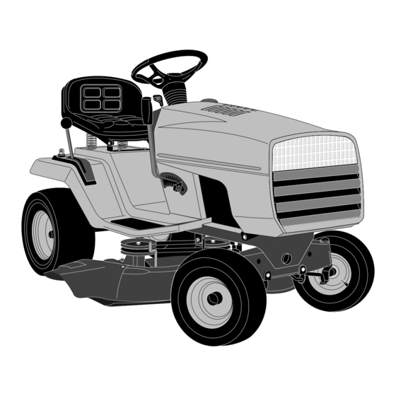
LR120/LR130
Instruction manual
Please read these instructions carefully
and make sure you understand them
before using this machine.
Anleitungshandbuch
Bitte lesen Sie diese Anleitungen
sorgfältig durch und vergewissern Sie
sich, daß Sie diese verstehen, bevor
Sie die Maschine in Betrieb nehmen.
PP PP PP PP
yy yy yy yy
@@ @@ @@ @@
@@ @@ @@ @@
@@ @@ @@ @@
@@ @@ @@ @@
PP PP PP PP
@@ @@ @@ @@
@@ @@ @@ @@
@@ @@ @@ @@
@@ @@ @@ @@
PP PP PP PP
PP PP PP PP
@@ @@ @@ @@
PP PP PP PP
@@ @@ @@ @@
PP PP PP PP
@@ @@ @@ @@
@@ @@ @@ @@
@@ @@ @@ @@
PP PP PP PP
@@ @@ @@ @@
@@ @@ @@ @@
@@ @@ @@ @@
PP PP PP PP
@@ @@ @@ @@
@@ @@ @@ @@
@@ @@ @@ @@
PP PP PP PP
@@ @@ @@ @@
@@ @@ @@ @@
@@ @@ @@ @@
PP PP PP PP
@@ @@ @@ @@
@@ @@ @@ @@
@@ @@ @@ @@
PP PP PP PP
PP PP PP PP
@@ @@ @@ @@
@@ @@ @@ @@
PP PP PP PP
PP PP PP PP
@@ @@ @@ @@
PP PP PP PP
PP PP PP PP
PP PP PP PP
@@ @@ @@ @@
PP PP PP PP
PP PP PP PP
PP PP PP PP
@@ @@ @@ @@
PP PP PP PP
PP PP PP PP
PP PP PP PP
@@ @@ @@ @@
PP PP PP PP
PP PP PP PP
PP PP PP PP
@@ @@ @@ @@
PP PP PP PP
PP PP PP PP
PP PP PP PP
@@ @@ @@ @@
PP PP PP PP
PP PP PP PP
PP PP PP PP
@@ @@ @@ @@
PP PP PP PP
PP PP PP PP
PP PP PP PP
@@ @@ @@ @@
Manuel d'instructions
Merci de lire trés attentivement le
manuel d'instructions. Assurez-vous
d'avior tout compris avant d'utiliser ce
tracteur.
Manual de las instrucciones
Por favor lea cuidadosamente y
comprenda estas intrucciones antes
de usar esta maquina.
Manuale di istruzioni
Prima di utilizzare la macchina
leggete queste istruzioni con
attenzione ed accertatevi di averle
comprese bene.
Instructieboekje
Lees deze instructies aandachtig en
zorg dat u ze begrijpt voordat u deze
machine gebruikt.
Advertisement
Table of Contents


Need help?
Do you have a question about the LR120 and is the answer not in the manual?
Questions and answers