Table of Contents
Advertisement
Advertisement
Table of Contents

Related Manuals for Gigabyte GA-C7V7-RH


Summary of Contents for Gigabyte GA-C7V7-RH
- Page 1 GA-C7V7-RH VIA C7 Processor Motherboard User's Manual Rev. 100 12ME-C7V7RH-1001R...
-
Page 2: Table Of Contents
Table of Contents GA-C7V7-RH Motherboard Layout ................3 Block Diagram ........................ 4 Chapter 1 Hardware Installation ..................5 Considerations Prior to Installation ..............5 Feature Summary .................... 6 Installation of Memory ..................8 Installation of Expansion Cards ................ 9 I/O Back Panel Introduction ................10 Connectors Introduction ................... -
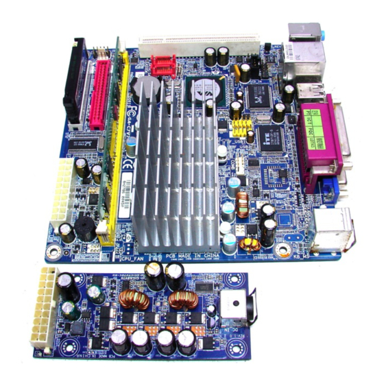
Page 3: Ga-C7V7-Rh Motherboard Layout
GA-C7V7-RH Motherboard Layout CPU_FAN VIA C7 RCA SV BIOS COMB CN700 IT8712 IDE1 IDE2 F_USB2 F_USB1 CLR_CMOS RTL8100C VT8237R Plus F_AUDIO CD_IN SATA2 AUDIO SATA1 SPDIF_IO CODEC SYS_FAN F_PANEL PCI1 - 3 -... -
Page 4: Block Diagram
Block Diagram VIA C7 Processor 533/400 MHz FSB VGA Port 533/400 MHz S-Video / AV out DDRII CN700 RJ45 1 PCI RTL8100C 2 Serial ATA VT8237R Plus BIOS LPC BUS LPT Port IT8712 PS/2 KB/Mouse ATA33/66/100/133 COM Ports 6 Channel 8 USB IDE Channels CODEC... -
Page 5: Chapter 1 Hardware Installation
Chapter 1 Hardware Installation Considerations Prior to Installation Preparing Your Computer The motherboard contains numerous delicate electronic circuits and components which can become damaged as a result of electrostatic discharge (ESD). Thus, prior to installation, please follow the instructions below: 1. -
Page 6: Feature Summary
1 parallel port 1 COMA port 1 VGA port 1 TV Out (Optional) 1 S-Video port (Optional) 4 USB 2.0/1.1 ports 1 RJ-45 port 3 audio jacks (Line In / Line Out / MIC In) GA-C7V7-RH Motherboard - 6 -... - Page 7 I/O Control IT8712 chip Hardware Monitor System voltage detection CPU / System temperature detection CPU / System fan speed detection CPU warning temperature CPU / System fan failure warning Supports CPU / System Smart Fan function BIOS Use of licensed AWARD BIOS Form Factor Mini-ITX form factor;...
-
Page 8: Installation Of Memory
DIMM socket. Then push it down. Fig.2 Close the plastic clip at both edges of the DIMM sockets to lock the DIMM module. Reverse the installation steps when you wish to remove the DIMM module. GA-C7V7-RH Motherboard - 8 -... -
Page 9: Installation Of Expansion Cards
Installation of Expansion Cards You can install your expansion card by following the steps outlined below: 1. Read the related expansion card's instruction document before installing the expansion card into the computer. 2. Remove your computer's chassis cover, screws and slot bracket from the computer. 3. -
Page 10: I/O Back Panel Introduction
Devices like CD-ROM, walkman etc. can be connected to Line In jack. Line Out (Front Speaker Out) Connect the stereo speakers, earphone or front surround channels to this connector. MIC In Microphone can be connected to MIC In jack. GA-C7V7-RH Motherboard - 10 -... -
Page 11: Connectors Introduction
Connectors Introduction CD_IN IDE1/ IDE2 SPDIF_IO SATA1 / SATA2 COMB CPU_FAN / SYS_FAN F_USB1 / F_USB2 F_PANEL F_AUDIO CLR_CMOS - 11 - Hardware Installation... - Page 12 Pin No. Definition 3.3V 3.3V Power Good 5V SB (stand by +5V) +12V 3.3V -12V PS_ON(soft on/off) GA-C7V7-RH Motherboard - 12 -...
- Page 13 2) IDE1 / IDE2 (IDE Connector) An IDE device connects to the computer via an IDE connector. One IDE connector can connect to one IDE cable, and the single IDE cable can then connect to two IDE devices (hard drive or optical drive).
-
Page 14: Cooler Fan Power Connector
Remember to connect the CPU/system fan cable to the CPU_FAN/SYS_FAN connector to prevent CPU damage or system hanging caused by overheating. CPU_FAN Pin No. Definition +12V Sense SYS_FAN F_PANEL (Front Panel Connector) Pin No. Definition Pin No. Definition HD_LED+ MSGLED+ HD_LED- MSGLED- PWRSW RESET ACT_LED+ ACT_LED- GA-C7V7-RH Motherboard - 14 -... - Page 15 6) F_AUDIO (Front Audio Panel Connector) If you want to use Front Audio connector, you must remove 5-6, 9-10 Jumper. In order to utilize the front audio header, your chassis must have front audio connector. Also please make sure the pin assigments on the cable are the same as the pin assigments on the MB header.
- Page 16 COMB cable, incorrect connection between the cable and connector will make the device unable to work or even damage it. For optional COMB cable, please contact your local dealer. Pin No. Definition NDCDB- NSINB NSOUTB NDTRB- NDSRB- NRTSB- NCTSB- NRIB- No Pin GA-C7V7-RH Motherboard - 16 -...
- Page 17 10) F_ USB1 / F_USB2 (Front USB Connector) Be careful with the polarity of the front USB connector. Check the pin assignment carefully while you connect the front USB cable, incorrect connection between the cable and connector will make the device unable to work or even damage it. For optional front USB cable, please contact your local dealer.
- Page 18 You may clear the CMOS data to its default values by this header. To clear CMOS, temporarily short the two pins. Default doesn't include the jumper to avoid improper use of this header. Open: Normal Short: Clear CMOS GA-C7V7-RH Motherboard - 18 -...
-
Page 19: Chapter 2 Bios Setup
Chapter 2 BIOS Setup BIOS (Basic Input and Output System) includes a CMOS SETUP utility which allows user to configure required settings or to activate certain system features. The CMOS SETUP saves the configuration in the CMOS SRAM of the motherboard. When the power is turned off, the battery on the motherboard supplies the necessary power to the CMOS SRAM. -
Page 20: The Main Menu (For Example: Bios Ver. :F4)
Fail-Safe Defaults indicates the value of the system parameters which the system would be in safe configuration. Load Optimized Defaults Optimized Defaults indicates the value of the system parameters which the system would be in best performance configuration. GA-C7V7-RH Motherboard - 20 -... - Page 21 Set Supervisor Password Change, set, or disable password. It allows you to limit access to the system and Setup, or just to Setup. Set User Password Change, set, or disable password. It allows you to limit access to the system. Save &...
-
Page 22: Standard Cmos Features
(Default value) None Select this if no SATA IDE devices are used and the system will skip the automatic detection step and allow for faster system start up. Capacity Capacity of currently installed hard disk. GA-C7V7-RH Motherboard - 22 -... - Page 23 Cylinder Number of cylinders Head Number of heads Precomp Write precomp Landing Zone Landing zone Sector Number of sectors Video The category detects the type of adapter used for the primary system monitor that must match your video display card and monitor. Although secondary monitors are supported, you do not have to select the type in setup.
-
Page 24: Advanced Bios Features
Select boot sequence for onboard(or add-on cards) SCSI, RAID, etc. Use < > or < > to select a device, then press<+> to move it up, or <-> to move it down the list. Press <ESC> to exit this menu. GA-C7V7-RH Motherboard - 24 -... - Page 25 Virus Warning If it is set to enable, the category will flash on the screen when there is any attempt to write to the boot sector or partition table of the hard disk drive. The system will halt and the warning message will appear in the mean time.
- Page 26 Video Shadow will increase the video speed. Enabled Video shadow is enabled .(Default Value) Disabled Video shadow is desibled. Small Logo(EPA) Show Enabled Small logo(EPA) show is enabled .(Default Value) Disabled Small logo(EPA) show is desibled. GA-C7V7-RH Motherboard - 26 -...
-
Page 27: Advanced Chipset Features
Advanced Chipset Features Phoenix- AwardBIOS CMOS Setup Utility Advanced Chipset Features DRAM Clock/Drive Control [Press Enter] Item Help AGP & P2P Bridge Control [Press Enter] Menu Level CPU & PCI Bus Control [Press Enter] Memory Hole [Disabled] Select Hard Disk Boot System BIOS Cacheable [Enabled] Device Priority... - Page 28 Current DRAM Frequency Detect DRAM fruquency automatically. DRAM Clock By SPD Set DRAM Clock by SPD.(Default Value) 200MHz Set DRAM Clock to 200MHz. 266MHz Set DRAM Clock to 266MHz. 333MHz Set DRAM Clock to 333MHz. GA-C7V7-RH Motherboard - 28 -...
- Page 29 DRAM Timing Auto By SPD Set DRAM timing auto by SPD.(Default Value) Manual Set DRAM timing by manually. SDRAM CAS Latency Set SDRAM CAS Latency to DDR / DDR2.5 / 4 Bank Interleave Disabled Set bank interleave to Disabled.(Default Value) Enabled Set bank interleave to Enabled.
- Page 30 Set VGA share memory to 16M. Set VGA share memory to 32M. Set VGA share memory to 64M.(Default value) Direct Frame Buffer Disabled Disabled direct fram buffer function. Enabled Enabled direct fram buffer function. (Default value) GA-C7V7-RH Motherboard - 30 -...
- Page 31 Select Display Device [CRT] [LCD] [TV] [DVI] [HDTV] [CRT+LCD] [CRT+TV] [CRT+DVI] [CRT+HDTV] [DVI+HDTV] [LCD+DVI] [TV+DVI].(Default value:CRT) Panel Type Disabled Disabled panel type. Enabled Panel Type [Key in a HEX number]. Outport Port Set outport port to DIO. (Default value) Set outport port to DI1. Dithering Disabled Disabled this function.(Default value)
- Page 32 This feature allows you to select the first initiation of the monitor display from which card when you install a PCI card and a VGA card on the motherboard. Set Init display first to VGA card. PCI slot Set Init display first to PCI.(Default value) GA-C7V7-RH Motherboard - 32 -...
-
Page 33: Integrated Peripherals
Integrated Peripherals Phoenix- AwardBIOS CMOS Setup Utility Integrated Peripherals VIA OnChip IDE Device [Press Enter] Item Help VIA OnChip PCI Device [Press Enter] Menu Level SuperIO Device [Press Enter] Onboard Lan Boot ROM [Disabled] Onboard H/W LAN [Enabled] : Move Enter: Select +/-/PU/PD: Value F10: Save... -
Page 34: Superio Device
Disable onboard SATA port. SATA Mode Select onboard Seria ATA function as IDE.(Default value) RAID Select onboard Seria ATA function as RAID.. IDE DMA transfer access Enabled Enable IDE DMA transfer access. (Default value) Disabled Disable this function. GA-C7V7-RH Motherboard - 34 -... - Page 35 On-Chip IDE Channel0 Enabled Enable onboard 1st channel IDE port. (Default value) Disabled Disable onboard 1st channel IDE port. On-Chip IDE Channel1 Enabled Enable onboard 2nd channel IDE port. (Default value) Disabled Disable onboard 2nd channel IDE port. IDE Prefetch Mode Enabled Enable IDE Prefetch mode.
- Page 36 This function decide whether to invoke the boot ROM of the onboard LAN chip. Enabled Enable this function. (Default value) Disabled Disable this function. Onboard H/W LAN Enabled Enable onboard H/W LAN function. (Default value) Disabled Disable this function. GA-C7V7-RH Motherboard - 36 -...
-
Page 37: Power Management Setup
Power Management Setup Phoenix- AwardBIOS CMOS Setup Utility Power Management Setup ACPI function [Enabled] Item Help ACPI Suspend Type [S1(POS)] Menu Level Power Management Option [User Define] HDD Power Down [Disabled] Suspend Mode [Disabled] Video Off Option [Suspend -> Off] Video Off Method [V/H SYNC+Blank] Modem Use IRQ... - Page 38 (Default value) Blank screen BIOS will only black monitor when gets into Green mode. DPMS Support BIOS will use DPMS Standard to control VGA card. (The Green type VGA card will turn of V/H-SYNC automatically.) GA-C7V7-RH Motherboard - 38 -...
- Page 39 Modem Use IRQ Set Modem use IRQ to NA. (Default value) Set Modem use IRQ to 3. Set Modem use IRQ to 4. Set Modem use IRQ to 5. Set Modem use IRQ to 7. Set Modem use IRQ to 9. Set Modem use IRQ to 10.
- Page 40 Everyday, 1~31 Time (hh: mm: ss) Alarm : (0~23) : (0~59) : (0~59) Primary INTR Disable this function. Enable this function. (Default value) IRQ (3,4,5,6,7,8,9, 10,11,12,13,14,15) Disabled Disable this function. (Default value) Enabled Enable this function. GA-C7V7-RH Motherboard - 40 -...
-
Page 41: Pnp/Pci Configurations
PnP/PCI Configurations Phoenix- AwardBIOS CMOS Setup Utility PnP / PCI Configurations PNP OS Installed [No] Item Help Reset Configuration Data [Disabled] Menu Level Resources Controlled By [Auto(ESCD)] x IRQ Resources Press Enter PCI/VGA Palette Snoop [Disabled] Assign IRQ For VGA [Enabled] Assign IRQ For USB [Enabled]... -
Page 42: Pc Health Status
Current DDRII Voltage(V) / Vcore / DDR+5V / +3.3V / +12V Detect system's voltage status automatically. Current System / CPU Temperature Detect System / CPU temperature automatically. Current CPU / SYSTEM FAN Speed (RPM) Detect CPU / System fan speed status automatically. GA-C7V7-RH Motherboard - 42 -... -
Page 43: Frequency / Voltage Control
Frequency / Voltage Control Phoenix- AwardBIOS CMOS Setup Utility Frequency / Voltage Control Auto Detect PCI Clk [Enabled] Item Help Spread Spectrum [+-0.25%] Menu Level CPU / PCIEX / AGP / PCI [Default] DIMM OverVoltage [Auto] : Move Enter: Select +/-/PU/PD: Value F10: Save ESC: Exit... -
Page 44: Load Fail-Safe Defaults
PC Health Status Exit Without Saving ESC: Quit : Select Item F10: Save & Exit Setup Load Optimized Defaults Selecting this field loads the factory defaults for BIOS and Chipset Features which the system automatically detects. GA-C7V7-RH Motherboard - 44 -... -
Page 45: Set Supervisor/User Password
2-10 Set Supervisor/User Password Phoenix- AwardBIOS CMOS Setup Utility Standard CMOS Features Frequency/Voltage Control Advanced BIOS Features Load Fail-Safe Defaults Advanced Chipset Features Load Optimized Defaults Integrated Peripherals Set Supervisor Password Enter Password: Power Management Setup Set User Password PnP/PCI Configurations Save &... -
Page 46: Save & Exit Setup
Exit Without Saving ESC: Quit : Select Item F10: Save & Exit Setup Abandon all Data Type "Y" will quit the Setup Utility without saving to RTC CMOS. Type "N" will return to Setup Utility. GA-C7V7-RH Motherboard - 46 -... - Page 47 - 47 - BIOS Setup...
- Page 48 GA-C7V7-RH Motherboard - 48 -...
Need help?
Do you have a question about the GA-C7V7-RH and is the answer not in the manual?
Questions and answers