Table of Contents
Advertisement
Quick Links
Advertisement
Table of Contents

Related Manuals for Zero88 Solution

Summary of Contents for Zero88 Solution
- Page 1 & Operating Manual...
- Page 2 Solution & Solution XL Operating Manual If a portable or temporary three phase mains Federal Communications Commission Document Ref : IM 9210 supply is used to power this desk, we This equipment has been tested and found to comply Issue 1.0 - Software Version 7.3...
-
Page 3: Table Of Contents
Submaster Setup Window ......108 Front Panel Controls ...........8 Selecting Fixtures ..........82 Submaster Setup Window ......108 Solution & Solution XL Quick Start Guide .... 19 Controlling Fixture Parameters ......82 Programming Submasters ......111 Getting Started ..........19 Tagging Parameters .......... - Page 4 Other Features ............ 137 Remote Switches (Optional Upgrade) .... 154 Monitor Windows ..........137 Supported Touchscreens ........155 Screen Navigation Keys ......... 138 Index ..............156 Desktop ............139 Solution & Solution XL Operating Manual – Issue 1.0 Page 4...
-
Page 5: Introduction
Multi Function Keys (MFKs) and soft buttons which appear on the monitor screens are displayed as follows: [Patch], [Desk Setup], [Files], [Clear Options]. The Solution & Solution XL Lighting Desk A summary of the main functions of the Solution & Solution XL lighting desk is as follows: This Manual Control Channels This manual describes the operation of the Solution and Solution XL lighting desks. - Page 6 Fixtures Groups The Solution & Solution XL desks can control up to 200 fixtures. Fixtures can The desk provides 400 user definable groups. Automatic groups for each be a simple generic lamp or colour scroller, a moving mirror or moving head fixture type can be generated from the Setup area, if required.
- Page 7 The USB ports on the desk support keyboard, mouse, external touch screens, memory sticks, USB CDRW drives, USB floppy disk drives and desk lights. Solution & Solution XL Operating Manual – Issue 1.0 Page 7...
-
Page 8: Front Panel Controls
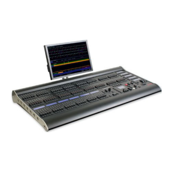
Controls Figure 1 - Solution desk layout This section of the manual describes the various controls and displays on the front panel of the Solution & Solution XL desk. The front panel controls have been divided into the following sections: ... - Page 9 Wide mode. maximum output levels from the PRESET B FADERS. The Solution XL desk has 96 preset faders arranged as two rows of 48 faders Wide Operation – The A MASTER and B MASTER faders control the and buttons.
- Page 10 MFKs are showing another function. This allows simultaneous selection of fixtures whilst still manipulating attributes, for example. Solution & Solution XL Operating Manual – Issue 1.0 Page 10...
- Page 11 Release the COLOUR key and the MFKs return to being fixture selection keys. – turns the block of 20 MFK‟s into Special function keys. SPECIAL Solution & Solution XL Operating Manual – Issue 1.0 Page 11...
- Page 12 The second (and third if fixture number. The second and third lines show the fixture name, eg Mac required) lines show the palette name. 300 : Mode 4. Solution & Solution XL Operating Manual – Issue 1.0 Page 12...
- Page 13 Submaster Window. The Submaster STEP button is used to manually step through any chases with manual drive being output on the submasters, or to initiate Beat tempo matching. Solution & Solution XL Operating Manual – Issue 1.0 Page 13...
- Page 14 Step Button The STEP button is used to manually step through any chase memory with manual drive currently being output on the Playback X. Solution & Solution XL Operating Manual – Issue 1.0 Page 14...
- Page 15 When any of the other main windows (Program Window, Outputs, Groups etc.) are selected, the Main LCD displays a simple text message directing you to refer to the monitor, plus the desk software version and other helpful information, for example: Output Window See Monitor for details For help press SHIFT & LEFT & RIGHT support.zero88.com Solution & Solution XL Operating Manual – Issue 1.0 Page 15...
- Page 16 UPDATE - used to update loaded items or items modified in the Program Plus (+) and Minus (-) - used to increment or decrement the value of the Window. current selection. NAME - used for naming memories, submasters, palettes etc. Solution & Solution XL Operating Manual – Issue 1.0 Page 16...
- Page 17 SHIFT - used in conjunction with various front panel controls to provide Main LCD, monitor screens and popup windows. additional functions, eg holding SHIFT and pressing the COLOUR key displays the Colour Palette Window on the monitor. Solution & Solution XL Operating Manual – Issue 1.0 Page 17...
- Page 18 The three control wheels are used for setting fixture parameter levels and other data. The names of the fixture parameters or other data currently assigned to each of the wheels and their values is shown on the Wheel LCD. Solution & Solution XL Operating Manual – Issue 1.0 Page 18...
-
Page 19: Solution & Solution Xl Quick Start Guide
Solution & Solution XL Quick Start Guide Welcome to the Solution & Solution XL Quick Start Guide. This chapter is intended to get you started using your new desk – for full information, please see the relevant chapters of this User Manual. -
Page 20: Controlling Dimmers
Now select the memory number to be programmed, if different to the one already selected. This can be done using the + and – keys, or by pressing ENTER then using the MFKs to enter a numeric value. Solution & Solution XL Operating Manual – Issue 1.0 Page 20... -
Page 21: Quick Start Guide
Select the first programmed memory using the arrow keys and press the GO button. The memory fades up according to it‟s programmed fade and delay times. Figure 4 - Name Memories Window Solution & Solution XL Operating Manual – Issue 1.0 Page 21... - Page 22 Beamshape and Position fades will occur in the times programmed. necessary, all fades may be controlled by the OVERRIDE and PAUSE controls on the front panel. To resume a paused fade, press the GO button. Solution & Solution XL Operating Manual – Issue 1.0 Page 22...
-
Page 23: Submasters
You can now use the MFKs to enter the submaster name as required and press [OK] to complete the operation. The name will be displayed on the Submaster LCD, above the fader. Solution & Solution XL Operating Manual – Issue 1.0 Page 23... - Page 24 The new scene, chase or transferred memory associated with the fader or button is not made available until the fader is brought back down to zero or the flash button is released. Solution & Solution XL Operating Manual – Issue 1.0 Page 24...
-
Page 25: Program Window
The Program Window is central to the programming functionality on the Solution & Solution XL desk. It is recommended (but not mandatory) that the area of the desk. Setup is used for all of the major functions on the desk,... - Page 26 Address] MFK or soft button on the window. Press ENTER to confirm. Select the first letter of the fixture manufacturer (eg M) and then the manufacturer (eg MARTIN) using the MFKs. Solution & Solution XL Operating Manual – Issue 1.0 Page 26...
- Page 27 To generate any or all of these items, press the [Auto Menus] MFK, then press [Create Auto Groups], [Create Auto Palettes] or [Create Auto Macros] MFK. For further details see the Setup chapter of the manual. Solution & Solution XL Operating Manual – Issue 1.0 Page 27...
- Page 28 MFK or soft button on the monitor. A summary of the Desk Setup options are provided below. For full details of the various options refer to the Setup chapter in the User Manual. Solution & Solution XL Operating Manual – Issue 1.0 Page 28...
- Page 29 Saving Shows Loading Shows The Solution & Solution XL saves the show automatically to its internal Note: Loading a show file will clear any existing show data from the memory at regular intervals. External backups of the show data can be made desk so ensure that you have backed up your previous show before you to a USB Storage Device (eg memory stick).
- Page 30 DMX patch to the factory defaults. Figure 12 - Clear Options Exiting Setup Once you have finished making changes to the setup, press the SETUP key to exit setup. Solution & Solution XL Operating Manual – Issue 1.0 Page 30...
-
Page 31: Controlling Fixtures
Tagging Parameters Controlling Fixture Parameters On the Solution & Solution XL desk fixture parameters must be „tagged‟ for them to be recorded. Each fixture type has it‟s own set of parameters (intensity, color, gobo, pan, tilt The tag status of each fixture parameter is indicated on the Wheel LCD etc.) which are classified or grouped together into different attributes (Colour,... -
Page 32: Palettes
Palettes Programming a palette is simple. Set up the fixture outputs as required, The Solution & Solution XL desk provides four sets of 400 palettes. The ensuring that the correct parameters are tagged. Press the COLOUR, palettes are stored under the headings of Colour, Beamshape, Position and BEAMSHAPE or POSITION key to make the MFKs palette selection keys. - Page 33 Holding down the TIME key and pressing a palette MFK will crossfade to the palette output values in the internal Fade Time. The internal Fade Time can be found and adjusted on Special Page 1 of the MFKs. Solution & Solution XL Operating Manual – Issue 1.0 Page 33...
-
Page 34: Setup
To select any of the other Setup options (Desk Setup, Files etc.) press the corresponding MFK or click on the corresponding button in the Setup Window on the monitor. To exit Setup, press the SETUP key on the front panel. Solution & Solution XL Operating Manual – Issue 1.0 Page 34... -
Page 35: Patch
Add Fixtures This option allows you to add fixtures to the fixture schedule, assign the fixtures to the fixture selection buttons (MFKs) and optionally patch them to DMX output addresses. Solution & Solution XL Operating Manual – Issue 1.0 Page 35... - Page 36 Mode 4) and the desk will load the fixture profile, ready for patching. case the MFKs will need to be paged in order to select the fixture you require. The Page Up/Down buttons are used to select the required page. Solution & Solution XL Operating Manual – Issue 1.0 Page 36...
- Page 37 To patch to the next available address in the selected universe use the [Next Address] button. Once you have set the DMX address required, press the ENTER button to confirm. Solution & Solution XL Operating Manual – Issue 1.0 Page 37...
-
Page 38: Editing Fixtures
Before carrying out any of the edit fixture operations - Select the fixture(s) to be edited using the fixture selection keys (MFKs). As each fixture is selected it is added to the Edit Fixtures screen on the monitor. Fixtures can be removed from this selection by pressing their fixture selection key (MFK) at any time. Solution & Solution XL Operating Manual – Issue 1.0 Page 38... - Page 39 ALL row to edit the value for all the selected fixtures. The 48 or 96 dimmers on the Solution and Solution XL desks respectively default to being patched to DMX addresses 1 – 48 or 1 – 96 on universe 1.
- Page 40 When duplicates are patched for the selected fixture(s) additional columns are added to the Edit Fixtures table (one column per duplicate address). Figure 23 - Patching Fixtures in Edit Fixtures Solution & Solution XL Operating Manual – Issue 1.0 Page 40...
- Page 41 DMX Address field. Press the [Unpatch] button. A confirmation popup window will be displayed. Select the [Yes] button to comfirm the operation. Solution & Solution XL Operating Manual – Issue 1.0 Page 41...
- Page 42 The new DMX In functionality allows you to add additional dimmers to the The DMX-In Field desk beyond the 48 or 96 that are provided by default on the Solution and Solution XL desks. The DMX-In field in the Patch table shows the DMX In address assigned to the fixture (if applicable).
- Page 43 1001 onwards, relative to the DMX address of the fixture Select the fixture(s) to be changed. Select the [Patch] button in the Edit assigned, for example: Fixtures Window: Solution & Solution XL Operating Manual – Issue 1.0 Page 43...
-
Page 44: Auto Menus
No Gobo – This auto palette sends all the „Gobo‟ parameters to their default values. Press the [Auto Menus] MFK or select the [Auto Menus] button on the Setup Window Shutter - Two auto palettes (Shutter Open and Shutter Closed). Solution & Solution XL Operating Manual – Issue 1.0 Page 44... -
Page 45: Patch Views
Figure 30 - Outputs View Pressing the [Universe View] button produces a drop down menu allowing you to select either universes 1 and 2 or universes 3 and 4 to be displayed. Solution & Solution XL Operating Manual – Issue 1.0 Page 45... - Page 46 Pressing the [Universe View] button produces a drop down menu allowing you Figure 31 - Fixtures View to select either universes 1 and 2 or universes 3 and 4 to be displayed. Solution & Solution XL Operating Manual – Issue 1.0 Page 46...
- Page 47 Setup Solution & Solution XL Operating Manual – Issue 1.0 Page 47...
-
Page 48: Desk Setup
Outputs – Map DMX universe to physical DMX outputs on the desk. Set Time – Set the time on the desk. Behaviour – Confirm Overwrites; Recovery Mode; Preset Mixing; Keep Parameters Separate options. Solution & Solution XL Operating Manual – Issue 1.0 Page 48... - Page 49 If the timeout period is reached - the front panel LCDs and monitor screen The touchscreen drivers currently supported by Solution & Solution will be turned off. To restore the LCDs and monitor screen, press any key XL are listed later in this user manual –...
- Page 50 Position attribute is selected. In this situation, the mouse pointer is removed temporarily from the monitor screen. In all other situations, the mouse or trackball operation will remain unaffected. Solution & Solution XL Operating Manual – Issue 1.0 Page 50...
- Page 51 Note – SMPTE, MIDI, CAN and Remote Switches These input functions are only applicable if the optional upgrade card has been fitted to the Solution & Solution XL desk. Figure 36 - Desk Setup (Inputs) Solution & Solution XL Operating Manual – Issue 1.0...
- Page 52 DMX splitter, giving the same signal from those ports. This is sometimes useful for routing data in a flexible venue scenario Solution & Solution XL Operating Manual – Issue 1.0 Page 52...
- Page 53 Preset Mixing is set to HTP mode, the preset faders are NOT shown in adjusted, only Cyan will be tagged). If the attribute is set to „No‟ then as the Program Window. Solution & Solution XL Operating Manual – Issue 1.0 Page 53...
- Page 54 This screen can be useful for fault finding. Warning: Once in Desk Setup, an external USB mouse or touchscreen is required to exit. Click the X in the top right hand corner to exit. Solution & Solution XL Operating Manual – Issue 1.0 Page 54...
- Page 55 „Go Minus‟ to the previous memory numerically, or „Go Back‟ to the previous memory in the order you played them back. Figure 39 - Desk Setup (Memory Defaults) Solution & Solution XL Operating Manual – Issue 1.0 Page 55...
- Page 56 - These options determine which of the attributes (Colour, Beamshape etc.) are controlled by the physical position of the submaster fader : Figure 40 - Desk Setup (Submaster Defaults) Figure 41 - Submaster Controls... Solution & Solution XL Operating Manual – Issue 1.0 Page 56...
- Page 57 Figure 42 - Desk Setup (Set Date) 7:30:0 7:30 am 12:0:0 12:00 Noon Enter the day, month and year in the respective fields and select the [OK] 16:45:0 4:45 pm button. 0:0:0 12:00 Midnight Solution & Solution XL Operating Manual – Issue 1.0 Page 57...
-
Page 58: Files
Saving Shows To save a copy of your show, you first need a storage media. The Solution & Solution XL desk is supplied with a USB flash memory stick, although other storage media may be used with the console. Connect your media to a USB port on the desk (any port will do). If using an external floppy drive, remember to insert a floppy disk into the drive. - Page 59 Loading a show file will clear any existing show data from the desk so ensure that you have backed up your previous show before you load another one onto the desk. Show files from a Solution desk can be loaded into a Solution XL and vice versa. Figure 45 - Files (Load Show) Solution &...
- Page 60 This data can then be loaded into Excel or any other software package that supports CSV files. Figure 46 - Files (Export CSV) Figure 47 - Example Exported CSV File Solution & Solution XL Operating Manual – Issue 1.0 Page 60...
- Page 61 Any fixtures which are not in the library can be made using our Select the required file and then select the [OK] button. All the fixture types Fixture Tools – see our support website at http://support.zero88.com for full contained in the selected UFT file are loaded and added to the fixture library information and to obtain the free software.
- Page 62 Select the required Source Device. A list of files found on the source device is displayed in the window. Select the required fixture library file and then select the [OK] button. Solution & Solution XL Operating Manual – Issue 1.0 Page 62...
- Page 63 Motherboard BIOS NVR Location Operating System Version Software Version Serial Number Fixture Library Version Figure 52 - Desk Information Current Show Flash Size Solution & Solution XL Operating Manual – Issue 1.0 Page 63...
-
Page 64: Clear Options
Tip: Holding SHIFT and pushing Reset Desk will reset the desk to factory defaults AND prompt for the Operation Mode when rebooted. This mode is good for equipment rental suppliers who may wish to ship the desks out with this option visible the first time a user boots the desk. Solution & Solution XL Operating Manual – Issue 1.0 Page 64... -
Page 65: Network
Setup Network The Solution & Solution XL support various Ethernet communication protocols, for connecting to visualisation tools, PDA remote controls, etc. Details of these protocols are found in this section: IP Addresses Ethernet Basics IP Addresses are a devices identity on an Ethernet network. The address indicates where the device is located and in combination with Unlike DMX, Ethernet operates in a different topology. - Page 66 Wireless Routers. It is important that you ensure that there is only ONE DHCP host on a network – multiple DHCP hosts can cause malfunctioning of the system. Solution & Solution XL Operating Manual – Issue 1.0 Page 66...
- Page 67 Art-Net enabled devices include Media Servers, Moving Lights and also dedicated DMX output boxes such as the “1 Universe Ethernet Box” by Cooper Controls. The system will look something like this: Ethernet Switch Figure 54 - Simple Art-Net network Solution & Solution XL Operating Manual – Issue 1.0 Page 67...
- Page 68 Setup sACN (ANSI-E1.31) Solution & Solution XL can output DMX via the Streaming ACN standard for DMX over Ethernet transport. This standard is approved by ANSI and ESTA Each sACN universe can be either “Live” or “Preview” output – the Preview...
- Page 69 The first time you enable wireless in an area, the smartphone will search for all available wireless networks and will ask you if you want to connect to any it finds. At Solution & Solution XL Operating Manual – Issue 1.0 Page 69...
- Page 70 Press on the Desk name and click the connect button. For full information on the Remote, see the Remote chapter in this manual (Page 143). Solution & Solution XL Operating Manual – Issue 1.0 Page 70...
- Page 71 It is possible to connect ZerOS consoles together, or a console and an offline editor, to create a master and backup system. This tracking backup option is ideal for show-critical scenarios where a backup solution must be provided. For this purpose Phantom ZerOS can be considered to be a fully functioning console, with the presence of a ZerOS Unlock Dongle (Catalogue Number 00- 887-00).
- Page 72 Light Converse integration requires a Zero 88 Light Converse USB dongle. Once active, the system allows bidirectional control of fixtures, selection and patching via the Ethernet connection. Solution & Solution XL Operating Manual – Issue 1.0 Page 72...
- Page 73 Select the network interface you wish to connect WYSIWYG with (the IP When you have finished address is shown) using it, click DISCONNECT in Choose OK the Device Manager. Solution & Solution XL Operating Manual – Issue 1.0 Page 73...
- Page 74 Wings Zero Wire DMX is a wireless DMX transmission system from Zero 88. The It is possible to connect Ethernet based playback wings to the Solution & system can be output directly from the console via the [Network] options in Solution XL.
-
Page 75: Preset Operation
Preset Operation Figure 60 - Preset Faders The Solution desk has 48 preset faders which control 24 dimmer channels in Crossfade Time - To enable timed fades there is an internal Fade Time that is Two Preset mode or 48 dimmer channels in Wide mode. - Page 76 The Flash Mode must be set to LATCH using the FLASH MODE key on (providing the time taken to move the master faders was less than the Special Page 1. indicated time). Solution & Solution XL Operating Manual – Issue 1.0 Page 76...
-
Page 77: Wide Operation
In Wide Mode you are able to crossfade between, or combine two full width MASTER from 0% to full. A dipless crossfade occurs with the stored scene scenes, ie 48 channels on the Solution desk or 96 channels on the Solution fading out and the scene set on the preset faders fading in. -
Page 78: Programming
This mode enables full tracking behaviour and gives experienced programmers maximum flexibility. The Solution & Solution XL offer 3 different programming modes to cater for different knowledge levels and styles of show. It is important to understand Switching between operating modes the difference between the three, and to select the one most appropriate to your requirements. - Page 79 Smart Tag function, which is detailed later in this chapter (page 83). Tracking Basic is Tracking Mode with Smart Tags enabled. Tracking Advanced is Smart Tags disabled. This can be modified on Special Page 1 of the MFKs. Solution & Solution XL Operating Manual – Issue 1.0 Page 79...
-
Page 80: The Program Window
Program Window and shows the channel number, it‟s output Solution & Solution XL desk. It is recommended (but not mandatory) that the value and tag status. The colour coding for this section is as follows: Program Window is displayed on the monitor screen when programming memories, submasters and palettes. - Page 81 Details (DMX) – When this option is selected the fixture parameter values will be displayed as the parameter detail names (eg Red, Gobo 1) where they are defined in the fixture data. If parameter details are not defined, Solution & Solution XL Operating Manual – Issue 1.0 Page 81...
-
Page 82: Selecting Fixtures
Wheel LCD. If the fixture(s) has more than three parameters of the selected attribute pressing the attribute key (eg COLOUR) will select the next group of parameters. Solution & Solution XL Operating Manual – Issue 1.0 Page 82... -
Page 83: Tagging Parameters
Hold down the CLEAR key and press the POSITION key. can safely switch between enabled and disabled as required. Hold down the CLEAR key and press the EFFECTS key. Solution & Solution XL Operating Manual – Issue 1.0 Page 83... -
Page 84: Cue Only Option
The this table: internal fade time can be found and adjusted on Special Page 1 of the MFKs. Solution & Solution XL Operating Manual – Issue 1.0 Page 84... -
Page 85: Highlight Function
SHIFT key is held down and the control wheel is moved. The default wheel editing modes, a description of each mode and how to change the wheel editing modes are described in the following sections. Solution & Solution XL Operating Manual – Issue 1.0 Page 85... - Page 86 Fixture 4 Fixture 5 Original Value Fixture Parameter Fixture 1 Fixture 2 Fixture 3 Fixture 4 Fixture 5 New Value Original Value Change in Value New Value Change in Value Solution & Solution XL Operating Manual – Issue 1.0 Page 86...
- Page 87 The MFKs change to show the wheel editing modes available. Select the required wheel editing mode (eg Absolute). The MFKs return to the attribute setup options. Select the [OK] key to complete the operation. Solution & Solution XL Operating Manual – Issue 1.0 Page 87...
-
Page 88: Blind Mode
The format and layout of the Blind Program Window is identical to that of the Live Program Window. Setting dimmer and fixture parameter levels, tagging, untagging etc. is carried out in the same way in the Blind Program Window as the live one. Solution & Solution XL Operating Manual – Issue 1.0 Page 88... -
Page 89: Memories
The memory stack is played back using the front panel controls which include a MASTER fader and GO, PAUSE, OVERRIDE and STEP controls. Solution & Solution XL Operating Manual – Issue 1.0 Page 89... - Page 90 Brightness Attack – The transition of the dimmer and fixture brightness channels between steps (Snap, Slow Attack, Slow Decay, or Crossfade) Drive – The method by which the next step is triggered (Auto, Manual, Bass or Beat) Solution & Solution XL Operating Manual – Issue 1.0 Page 90...
-
Page 91: The Memories Window
Colour Fade – The Colour fade and delay times for the memory (see Notes). The delay time is only displayed if it is non-zero. Figure 71 - Information Bar Solution & Solution XL Operating Manual – Issue 1.0 Page 91... -
Page 92: The Memory Setup Window
Select the [Trigger] option, then select the required memory trigger (Go, Auto, Real Time, SMPTE or MIDI). If the Trigger is set to Auto – select the [Trigger Timecode] option and enter the required Wait time, for example: Solution & Solution XL Operating Manual – Issue 1.0 Page 92... - Page 93 Select the [Next] field in the Memory Setup Window. Enter the memory number to jump to and then press the [OK] button. Only valid programmed memory numbers are allowed. Solution & Solution XL Operating Manual – Issue 1.0 Page 93...
- Page 94 Enter the required macro number and then press ENTER to complete. Only valid programmed macro numbers are allowed. When a macro has been associated with a memory this is indicated in the Comments field on the Memories Window, eg M:23. Solution & Solution XL Operating Manual – Issue 1.0 Page 94...
- Page 95 Select the [Shots] option, then enter the number of shots requires (0 – 255). Select the [OK] button to complete the operation. Figure 75 - Memory Setup Window (Chase) Solution & Solution XL Operating Manual – Issue 1.0 Page 95...
-
Page 96: Programming Memories
Note – Programming Memories and Tracking parameters are untagged. The Solution & Solution XL desks operate, when in Tracking mode, as tracking consoles. This means that if a dimmer or fixture parameter is programmed in one memory, it will track through all subsequent Note –... -
Page 97: Setting Fade And Delay Times
Holding down the SHIFT key and moving the first finger wheel adjusts the To run the chase and adjust the modifers as required – see Memory Setup intensity fade down time only. Window. Solution & Solution XL Operating Manual – Issue 1.0 Page 97... - Page 98 0.5 ENTER 0.5 seconds 3 ENTER 3.0 seconds 60 ENTER 1 minute 1.30.0 ENTER 1 minute 30 seconds 15.0.0 ENTER 15 minutes Solution & Solution XL Operating Manual – Issue 1.0 Page 98...
-
Page 99: Editing Memories
Adjust the levels of the dimmer channels as required using the preset faders. Adjust the levels of the fixture parameters as required using the MFKs and control wheels. Press the UPDATE key. The Update Options Window is displayed on the monitor. Solution & Solution XL Operating Manual – Issue 1.0 Page 99... - Page 100 Press the UPDATE key. The Update Options Window is displayed on the monitor. Set the update options as required and then select the [OK] button to complete the edit. Solution & Solution XL Operating Manual – Issue 1.0 Page 100...
-
Page 101: Inserting Memories
Inserting Memories A memory cannot be inserted in the following places: The Solution & Solution XL desk provides the facility to insert up to a Between a whole number memory and its first insert (eg 2 and 2.01) maximum of 99 point memories between two whole number memories. -
Page 102: Copying Memories
Submaster field as shown in the example above. The Solution & Solution XL desk provides the facility to copy a complete memory (scene or chase) from one location in the memory stack to another. -
Page 103: Naming Memories
Memories Window, press the ENTER key, use the MFKs or external keyboard to enter the memory name and then press the ENTER key to complete the operation. Figure 86 - Delete Confirmation Solution & Solution XL Operating Manual – Issue 1.0 Page 103... -
Page 104: Playing Back Memories
+ and – keys or the UP and DOWN arrow keys to select the next memory to be output. The Next memory to be output is highlighted by a yellow bar. Solution & Solution XL Operating Manual – Issue 1.0 Page 104... - Page 105 LEDs in the GO key stop flashing and remain on. All fades may be controlled by the OVERRIDE and PAUSE controls on the front panel (see later in this section). Solution & Solution XL Operating Manual – Issue 1.0 Page 105...
- Page 106 When the Current memory is a chase with a Beat drive modifier, tapping the STEP key twice is used to set the speed (beat) of the chase. Solution & Solution XL Operating Manual – Issue 1.0 Page 106...
-
Page 107: Submasters
The Solution desk has 20 pages of 10 submasters. the submaster are triggered as the submaster fader is raised (0-100%). The Solution XL desk has 20 pages of 30 submasters. Chase Modifers – If the submaster is programmed directly with a chase Submasters may be programmed directly with a scene or chase. -
Page 108: Submaster Setup Window
Transferred range of memories – the first, current, next and last memory numbers. Macro data – number of macro triggered by the submaster. Chase Modifiers - Direct Chase or transferred Chase memory only. Solution & Solution XL Operating Manual – Issue 1.0 Page 108... - Page 109 Therefore, if you program a submaster with colour, beamshape and affect that fader. position data, but set the Submaster Controls… to Position and Colour, the following will happen. Solution & Solution XL Operating Manual – Issue 1.0 Page 109...
- Page 110 Select the [Macros …] option in the Submaster Setup Window. A Submaster Macro popup window is displayed: Figure 90 - Submaster Macros Figure 91 - Submaster Chase Modifiers Solution & Solution XL Operating Manual – Issue 1.0 Page 110...
-
Page 111: Programming Submasters
Note – Recording a Full Scene Holding down the SHIFT key and pressing the RECORD key will record all dimmers and fixture parameters – a ‘full’ scene onto the submaster. Solution & Solution XL Operating Manual – Issue 1.0 Page 111... - Page 112 Transferring Memories to Submasters Press the RECORD key. The Solution & Solution XL desk provides the facility to transfer a single programmed memory or a range of memories onto a submaster – see page A warning is displayed on the monitor and Main LCD with the following options: [Overwrite Scene], [Turn into Chase] and [Cancel].
-
Page 113: Editing Submasters
Set the update options as required and then select the [OK] button to control wheels. complete the edit. Press the UPDATE key. The Update Options Window is displayed on the monitor. Solution & Solution XL Operating Manual – Issue 1.0 Page 113... - Page 114 LOAD key. The Load Options Window is displayed on the monitor: Figure 97 - Loading a Transferred Chase Submaster Select the [OK] button to load the submaster into the programmer. Solution & Solution XL Operating Manual – Issue 1.0 Page 114...
-
Page 115: Copying A Submaster
Copying a Submaster displayed. You then have the option to overwrite the submaster or cancel the copy operation. The Solution & Solution XL desk provides the facility to copy a submaster from one location to another. Naming a Submaster Press the SUBMASTERS key to display the Submasters Window on the Main LCD and monitor. -
Page 116: Deleting A Submaster
The way that the data is output depends on how the submaster is programmed (ie direct scene, direct chase, transferred scene or transferred chase) and also on the various submaster parameters (fade times, trigger levels etc.) Solution & Solution XL Operating Manual – Issue 1.0 Page 116... - Page 117 Beamshape and Position channels are triggered and snap to their of the chase is therefore output as it was programmed. programmed levels in the scene when the submaster fader reaches the LTP Trigger level. Solution & Solution XL Operating Manual – Issue 1.0 Page 117...
-
Page 118: Submaster Flash Functions
The fixture Brightness channels are flashed to their programmed level. All other fixture Brightness channel data being output from other submasters or Playback X is reduced to zero. Solution & Solution XL Operating Manual – Issue 1.0 Page 118... - Page 119 The dimmers and fixture brightness channels return to zero (or the level where applicable. The outputs are not affected. corresponding to the submaster fader level if the fader is avove zero). Solution & Solution XL Operating Manual – Issue 1.0 Page 119...
-
Page 120: Groups
Groups Groups Introduction The Solution & Solution XL desk provides 400 user definable Groups. Groups are most commonly used when selecting fixtures and programming data to be recorded in memories, submasters and palettes. Automatic Groups - In Setup, there is an option to generate a set of automatic groups based on the fixture types in the schedule. -
Page 121: Recording A Group
You then have the option to overwrite the group or cancel the copy operation. Figure 102 - Naming a Group Use the MFKs or external keyboard to enter the group name as required, then select the [OK] button to complete the operation. Solution & Solution XL Operating Manual – Issue 1.0 Page 121... -
Page 122: Deleting A Group
The Delete Window is displayed on the monitor: Figure 104 - Deleting a Group Select the [OK] button. A confirmation window is displayed. You can then confirm the deletion or cancel the operation. Solution & Solution XL Operating Manual – Issue 1.0 Page 122... -
Page 123: Palettes
Palettes Palettes Introduction The Solution & Solution XL desk provides four sets of 400 palettes. The palettes are stored under the headings of Colour, Beamshape, Position and Effects. This chapter deals with Colour, Beamshape and Position palettes. The following chapter deals with Effects. -
Page 124: Editing A Palette
Press the UPDATE key. The Update Options Window is displayed on the monitor. Set the update options as required and then select the [OK] button to complete the edit. Solution & Solution XL Operating Manual – Issue 1.0 Page 124... -
Page 125: Copying A Palette
You then have the option to overwrite the palette or cancel the copy operation. the palette output values in the internal Fade Time. The internal Fade Time can be found and adjusted on Special Page 1 of the MFKs. Solution & Solution XL Operating Manual – Issue 1.0 Page 125... -
Page 126: Deleting A Palette
Figure 109 - Deleting a Colour Palette Select the [OK] button. A confirmation window is displayed. You can then confirm the deletion or cancel the operation. Solution & Solution XL Operating Manual – Issue 1.0 Page 126... -
Page 127: Effects
To display the Effects Palette Window on the monitor, hold down the SHIFT key and then press the EFFECTS key. The Solution & Solution XL desk provides a powerful effects generator with a number of standard effects. By adjusting the size, speed and offset values, a... -
Page 128: Effect Window
Figure 111 - Effects Window From within the Effect Window, each parameter of the selected fixture can be assigned an effect function, a speed, size and offset. Solution & Solution XL Operating Manual – Issue 1.0 Page 128... -
Page 129: Effect Parameters
Use the PAGE UP or PAGE DOWN keys to select the required page. Press and hold down the corresponding effect MFK for two seconds. The LED in the effect MFK is lit when the effect has been recorded. Solution & Solution XL Operating Manual – Issue 1.0 Page 129... -
Page 130: Editing An Effect
Press the UPDATE key. The Update Options Window is displayed on the monitor. Set the update options as required and then select the [OK] button to complete the edit. Solution & Solution XL Operating Manual – Issue 1.0 Page 130... -
Page 131: Copying An Effect
If the destination effect is unprogrammed – the source effect is copied to the destination effect. If the destination effect is programmed – a warning message is displayed. You then have the option to overwrite the effect or cancel the copy operation. Solution & Solution XL Operating Manual – Issue 1.0 Page 131... -
Page 132: Deleting An Effect
Press the DELETE key. The Delete Window is displayed on the monitor: Figure 115 - Deleting an Effect Select the [OK] button. A confirmation window is displayed. You can then confirm the deletion or cancel the operation. Solution & Solution XL Operating Manual – Issue 1.0 Page 132... -
Page 133: Macros
Macros Macros Introduction The Solution & Solution XL desk provides up to 400 user programmable macros. Automatic Macros - When you select the [Create Auto Macros] option in Setup, the desk generates a number of fixture related macros (Reset, Lamp On, Lamp Off). -
Page 134: Recording A Macro
LCD above the Macro MFK is displayed in inverse. Figure 118 - Macro Recording Indicator Press the MACRO key again to end the recording process. Solution & Solution XL Operating Manual – Issue 1.0 Page 134... -
Page 135: Naming A Macro
If the destination macro is unprogrammed – the source macro is copied to the destination macro. If the destination macro is programmed – a warning message is displayed. You then have the option to overwrite the macro or cancel the copy operation. Solution & Solution XL Operating Manual – Issue 1.0 Page 135... -
Page 136: Running A Macro
Off) select the fixture(s) first before running the macro as described above. Select the [OK] button. A confirmation window is displayed. You can then confirm the deletion or cancel the operation. Solution & Solution XL Operating Manual – Issue 1.0 Page 136... -
Page 137: Other Features
Other Features Monitor Windows The Solution & Solution XL desk allows you to display a number of different windows on the monitor screen at the same time and to select, resize and delete windows, as required. A window displayed on the monitor can be full-size, half-size or quarter-size, and can be displayed in a number of different positions, as illustrated below:... -
Page 138: Screen Navigation Keys
Selects a window by cycling through the windows on the SELECT monitor. Moves the window onto an alternative display, connected SCREEN via the remote monitors. Figure 124 - Multiple Palette Windows Solution & Solution XL Operating Manual – Issue 1.0 Page 138... -
Page 139: Desktop
Window Setup The Window Setup button allows you to change between various different settings for the output window. These settings are detailed earlier in the manual, on page 81. Solution & Solution XL Operating Manual – Issue 1.0 Page 139... -
Page 140: Dmx Output Window
@ or * > or / THRU Backspace FULL Remote Switch 1 … Remote CTRL + F1 … CTRL + F6 Switch 6 Figure 126 - DMX Output Window Solution & Solution XL Operating Manual – Issue 1.0 Page 140... -
Page 141: Software Updates
Zero 88 consoles have a long history of user-inspired development. If you have any questions on the operation of the desk, bug reports or a suggestion for a feature which is not currently included on the Solution & Solution XL or Facebook any of our other range of consoles, visit the Zero 88 Product Support Forum and make a post. - Page 142 Other Features Solution & Solution XL Operating Manual – Issue 1.0 Page 142...
-
Page 143: Remote
Select the desk you wish to connect to, and the mode you wish to connect in, and press the Connect button. Figure 128 - Connecting the Windows Remote Monitor Solution & Solution XL Operating Manual – Issue 1.0 Page 143... - Page 144 The dropdown box at the bottom of the window allows you to select a different screen of the remote. Figure 132 - Wheels Remote Figure 130 - Selecting Remote Screen Solution & Solution XL Operating Manual – Issue 1.0 Page 144...
- Page 145 Wheels. After selection your choice, the desk will connect and display your chosen screen. Figure 133 - Remote Timeout In this situation, Disconnect the remote by pressing Disconnect and then try connecting again. Solution & Solution XL Operating Manual – Issue 1.0 Page 145...
- Page 146 (likewise Desktop 4 and 5). Using Desktop 1 will show the outputs from the VGA connector on the back of the console, assuming these have been left as Desktop 1 . Solution & Solution XL Operating Manual – Issue 1.0 Page 146...
- Page 147 Select your desk and the connection will be made. Just like the Windows Remote Monitor, the iPad connects and emulates the monitor screens from the ORB. Again, you must select the Desktop you wish to view. Solution & Solution XL Operating Manual – Issue 1.0 Page 147...
- Page 148 Once the screen is selected, the iPad will redraw the monitor screen To change which desktop is being displayed, press the Desktop button in the bottom left of the screen and select a new view screen. Solution & Solution XL Operating Manual – Issue 1.0 Page 148...
-
Page 149: Glossary
Modifying the program data within the desk without Ethernet A computer networking system, used to communicate affecting the outputs. between IT devices. On the Solution & Solution XL the Ethernet port is used for Ethernet DMX output Blackout The BLACKOUT key sets the outputs of all dimmer and remote monitors, as well as connections to and fixture intensity channels to 0%. - Page 150 Direction, Speed, Fade and Shots. values. Parameters which are Highlighted are not Operating Mode The Solution & Solution XL desk has a three tagged. Highlight is most often used for editing the position of a fixture. operating modes that offer tracking and non-tracking...
- Page 151 Chase will run after being triggered. Video Graphics Array. The monitor outputs on the SMPTE Society of Motion Picture and Television Engineers. back of the Solution & Solution XL output as XGA. Memories can be set to be triggered by SMPTE timecode. Wheel LCD...
-
Page 152: Technical Specification
CAN Port (Optional Upgrade) Connections The desk also has an optional CAN port and is capable of supporting iCAN or Left Channel ChilliNet messages. Ring Right Channel 0V Signal Sleeve Ground Solution & Solution XL Operating Manual – Issue 1.0 Page 152... -
Page 153: External Storage Devices
External Storage Devices USB Ports The primary method of storage for the Solution & Solution XL is via USB Four external USB ports are fitted to the desk (one on front panel, three on Memory Sticks (also known as Flash Disks or Mass Storage Devices). These rear panel). -
Page 154: Dmx Input
Data on channels 1 – 512 only. 0V Common Ground Connector DMX Output Signal Ground (0V) DMX Drive Complement (1-) DMX Drive True (1+) Not Connected Not Connected Solution & Solution XL Operating Manual – Issue 1.0 Page 154... -
Page 155: Supported Touchscreens
Supported Touchscreens A number of external touchscreens are supported by the Solution & Solution XL. These screens connect into the desk using the USB connection. Screens with a serial connection will not work via a USB-Serial converter. The screen needs to have a direct USB connection. It is recommended only to purchase one of the known working screens from the list below, for use with your Solution &... -
Page 156: Index
Patch Functions ............ 39 Desk Information ..........62 Cue Only ..............84 Effect Loading Shows ............58 Cursor Keys ............... 17 Window .............. 128 Loading User Fixture Types ........60 Solution & Solution XL Operating Manual – Issue 1.0 Page 156... - Page 157 Memory Setup Window ........... 92 Outputs View ............45 MIDI ................ 146 Mode Macro Remote ..............69 Operating .............. 78 Setup Window ............ 134 PGM WIN Key ............17 Monitor Windows ........... 137 Solution & Solution XL Operating Manual – Issue 1.0 Page 157...
- Page 158 Selecting Operating Mode ........21 Programming Submasters ........112 Setting Up ............. 27 Absolute Mode ............. 85 Submaster Flash Functions ......... 119 Changing ............... 87 Submasters ............24 Submasters Setup Window ........ 109 Solution & Solution XL Operating Manual – Issue 1.0 Page 158...
- Page 159 Window Setup ............139 Fan V Mode ............86 Wireless Zero Wire ..............74 Relative Mode ............85 Access Point ............ 69, 74 Wheel LCD ..............20 DMX ..............74 Solution & Solution XL Operating Manual – Issue 1.0 Page 159...
- Page 160 Zero 88 Tel: +44 (0)1633 838088 For news, views and the latest software visit Usk House Fax: +44 (0)1633 867880 the Zero 88 Product Support Forum at: Llantarnam Park email: sales@zero88.com Cwmbran support.zero88.com Web: www.zero88.com NP44 3HD...
Need help?
Do you have a question about the Solution and is the answer not in the manual?
Questions and answers